
Summary of Contents for Price ULTRASUITE ARRAY
- Page 1 MANUAL – INSTALLATION ULTRASUITE ARRAY Operating Room Diffuser System with LED Lighting v100 – Issue Date: 09/07/18 © 2018 Price Industries Limited. All rights reserved.
-
Page 2: Table Of Contents
ULTRASUITE ARRAY TABLE OF CONTENTS Product Overview ............1 Pre-installation Instructions and Checklist ....2 Installation Instructions Luminaire Mounting and Installation ....... 3 Remote Driver Cabinet Mounting and Installation ..9 Electrical Connections ..........10... -
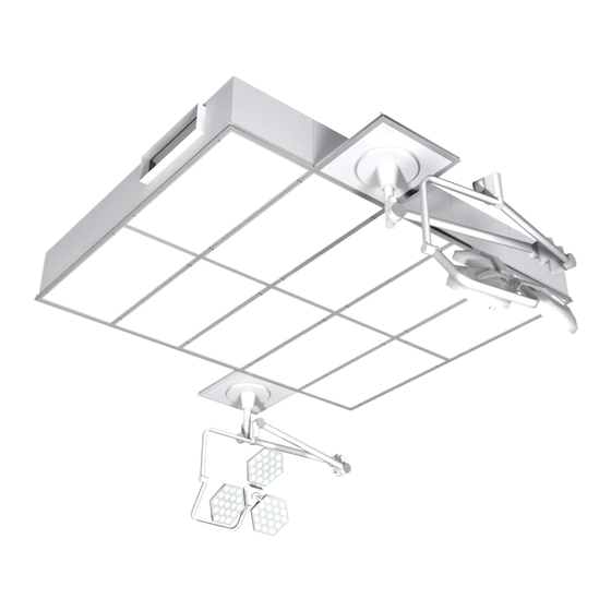
Page 3: Product Overview
ULTRASUITE ARRAY PRODUCT OVERVIEW The Price Ultrasuite Assembly (USA) luminaire modules will either be: • A stand-alone module (fig. 1); or • An array of module assemblies (fig 2) FIGURE 1: STAND-ALONE MODULE FIGURE 2: MODULE ARRAY The luminaire(s) will come with a remote LED driver cabinet with pre-wired driver connections (fig. 3). The quantity of drivers varies with the size of the luminaire system. -
Page 4: Pre-Installation Instructions And Checklist
If anything is found to be damaged, contact the shipping company and file a freight claim. • Review Price project specific submittals to ensure booms are located in the correct locations (recommended to measure and chalk outline of ceiling system on floor). -
Page 5: Installation Instructions
Ensure that the perimeter drywall (if installed) and other equipment are installed at the correct heights using a laser level. Step 4: Extend hanger wires 6 in. below the top of the plenum (refer to job specific submittal for plenum height) and snip to length as required. priceindustries.com | ULTRASUITE ARRAY - Manual... - Page 6 Step 6: Using a 3/16 in. Allen key, unscrew the damper mounting screw to release the aperture plate damper for access to the plenum (fig. 7, 8, 9, 10). FIGURE 7: LOOSEN DAMPER MOUNTING SCREW FIGURE 8: REMOVE DAMPER MOUNTING SCREW ULTRASUITE ARRAY - Manual | priceindustries.com...
- Page 7 ULTRASUITE ARRAY INSTALLATION INSTRUCTIONS FIGURE 9: APERTURE PLATE DAMPER REMOVAL FIGURE 10: OPEN PLENUM WITH FACE AND APERTURE DAMPER REMOVED priceindustries.com | ULTRASUITE ARRAY - Manual...
- Page 8 Step 9: Raise adjacent module assemblies, temporarily supporting the modules with hanger wire. Fasten modules together using bolts, metal washers, and lock nuts supplied by Price (fig. 12, 14). Module sections will have slotted holes for fastening (fig. 13). Bottom of modules should be flush and level prior to fastening together.
- Page 9 Step 12: Tighten hanger wire by twisting and securing per ASTM C636 and/or applicable local codes. Step 13: Re-install damper assembly and tighten the damper mounting screws. FIGURE 15: REPLACE DAMPER APERTURE PLATE FIGURE 16: TIGHTEN DAMPER MOUNTING SCREW priceindustries.com | ULTRASUITE ARRAY - Manual...
- Page 10 PANEL ALL METRIC DIMENSIONS ( ) ARE SOFT CONVERTED. IMPERIAL DIMENSIONS ARE CONVERTED TO M PROJECT: HGWC GRID INTEGRATION PERIMETER HALF TEE INTEGRATION ENGINEER: ULTRASUITE ARRAY - Manual | priceindustries.com CUSTOMER: SUBMITTAL DATE: REVISION: 0 © Copyright PRICE INDUSTRIES 2018...
-
Page 11: Remote Driver Cabinet Mounting And Installation
Step 4: Repeat above steps until all remote driver cabinets have been installed. NOTE: Remote driver cabinets must have a minimum of 6 in. clearance on all sides (fig. 21). FIGURE 20: REMOTE DIVER CABINET MOUNTING FIGURE 21: MULTIPLE REMOTE DRIVER CABINETS LOCATIONS INSTALLED priceindustries.com | ULTRASUITE ARRAY - Manual... -
Page 12: Electrical Connections
Wiring should be carried out by a certified electrician and meet national and local electrical codes. FIGURE 22: REMOVE REMOTE DRIVER CABINET FACE FIGURE 23: REMOTE DRIVER CABINET EQUIPMENT LAYOUT High Voltage Connection High Voltage Knockouts Terminal Blocks Barrier Low Voltage Connection Low Voltage Knockouts Terminal Blocks ULTRASUITE ARRAY - Manual | priceindustries.com... - Page 13 180 FT LINE/CONTROL LVTB 120-277 DRIVER 1 FROM DIMMER SWITCH G N DH L HVTB 24 VDC LOW VOLTAGE DIFFUSER/LED MODULE JUNCTION BOX priceindustries.com | ULTRASUITE ARRAY - Manual -001 1 DRIVER DASH NO. DESCRIPTION Description WIRING DIAGRAM - FIELD CONNECTIONS...
- Page 14 WIRING DIAGRAM - FIELD CONNECTIONS Drawn by Scale Status Date Drawing no. Revision Sheet (mm/dd/yyyy) 269685 2018-09-07 ULTRASUITE ARRAY - Manual | priceindustries.com Rev Description ECN Date (y/m/d) By Print Date: 2018-09-07 - 269685.dft Print Date: 2018-09-07 - 269685.dft Solid Edge...
- Page 15 WIRING DIAGRAM - FIELD CONNECTIONS Drawn by Scale Status Date (mm/dd/yyyy) Drawing no. Revision Sheet 269685 2018-09-07 Rev Description ECN Date (y/m/d) By priceindustries.com | ULTRASUITE ARRAY - Manual Print Date: 2018-09-07 - 269685.dft Print Date: 2018-09-07 - 269685.dft Solid Edge...
- Page 16 WIRING DIAGRAM - FIELD CONNECTIONS Drawn by Scale Status Date Drawing no. Revision Sheet (mm/dd/yyyy) 269685 2018-09-07 Rev Description ULTRASUITE ARRAY - Manual | priceindustries.com ECN Date (y/m/d) By Print Date: 2018-09-07 - 269685.dft Print Date: 2018-09-07 - 269685.dft Solid Edge...
- Page 17 WIRING DIAGRAM - FIELD CONNECTIONS Drawn by Scale Status Date Drawing no. Revision Sheet (mm/dd/yyyy) 269685 2018-09-07 Rev Description ECN Date (y/m/d) By priceindustries.com | ULTRASUITE ARRAY - Manual Print Date: 2018-09-07 - 269685.dft Print Date: 2018-09-07 - 269685.dft Solid Edge...
- Page 18 WIRING DIAGRAM - FIELD CONNECTIONS Drawn by Scale Status Date Drawing no. Revision Sheet (mm/dd/yyyy) 269685 2018-09-07 Rev Description ECN Date (y/m/d) By ULTRASUITE ARRAY - Manual | priceindustries.com Print Date: 2018-09-07 - 269685.dft Print Date: 2018-09-07 - 269685.dft Solid Edge...
- Page 19 ULTRASUITE ARRAY NOTES priceindustries.com | ULTRASUITE ARRAY - Manual...
- Page 20 This document contains the most current product information as of this printing. For the most up-to-date product information, please go to priceindustries.com © 2018 Price Industries Limited. All rights reserved.
Need help?
Do you have a question about the ULTRASUITE ARRAY and is the answer not in the manual?
Questions and answers