Stanley IW16 Series User Manual
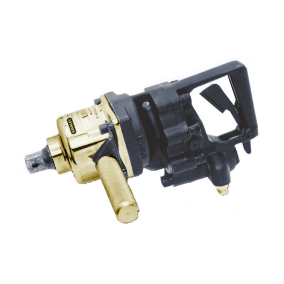
Hydraulic impact wrench
Hide thumbs
Also See for IW16 Series:
- User manual (22 pages) ,
- Safety, operation & maintenance (16 pages) ,
- User manual (20 pages)

Related Manuals for Stanley IW16 Series


Summary of Contents for Stanley IW16 Series
- Page 1 IW16 HYDRAULIC IMPACT WRENCH USER MANUAL Safety, Operation and Maintenance © 2014 STANLEY Black & Decker, Inc. New Britain, CT 06053 U.S.A. 66174 9/2018 Ver 29...
- Page 2 Provisiones especiales: Disposizioni speciali: Representative in the Union: Patrick Vervier, Stanley Dubuis 17-19, rue Jules Berthonneau-BP 3406 41034 Blois Cedex, France. Vertreter in der Union/Représentant dans l’union/Representante en la Union/Rappresentante presso l’Unione Done at/Ort/Fait à/Dado en/Fatto a STANLEY Infrastructure, Milwaukie, Oregon USA...
-
Page 3: Table Of Contents
REPAIRS AND / OR SERVICE TO THIS TOOL MUST ONLY BE DONE BY AN AUTHORIZED AND CERTIFIED DEALER. For the nearest certified dealer, call STANLEY Infrastructure at (503) 659-5660 and ask for a Customer Service Representative. IW16 User Manual ◄ 3... -
Page 4: Safety Symbols
SAFETY SYMBOLS Safety symbols and signal words, as shown below, are used to emphasize all operator, maintenance and repair actions which, if not strictly followed, could result in a life-threatening situation, bodily injury or damage to equipment. This is the safety alert symbol. It is used to alert you to potential personal injury hazards. -
Page 5: Safety Precautions
Inspect the tool before each use and ensure all de- • Do not use in confined spaces and beware of cals are legible. Contact STANLEY if replacements crushing hands between the tool and the workpiece, are needed. especially when unscrewing. - Page 6 SAFETY PRECAUTIONS Your risk from these exposures varies, depending on how often you do this type of work. To reduce your exposure to these chemicals: work in a well ventilated area, and work with approved safety equipment, such as those dust masks that are specially designed to filter out microscopic particles.
-
Page 7: Tool Stickers & Tags
SHOWN, MUST BE LEGIBLE AT ALL TIMES. REPLACE DECALS IF THEY BECOME WORN OR DAMAGED. REPLACEMENTS ARE AVAILABLE FROM YOUR LOCAL STANLEY DISTRIBUTOR. The safety tag (P/N 15875) at right is attached to the tool when shipped from the factory. Read and understand the safety instructions listed on this tag before removal. -
Page 8: Hose Types
This hose is not certifi ed non-conductive and must never be used near electrical conductors. HOSE SAFETY TAGS To help ensure your safety, the following DANGER tags are attached to all hose purchased from STANLEY. DO NOT REMOVE THESE TAGS. -
Page 9: Hose Recommendations
HOSE RECOMMENDATIONS IW16 User Manual ◄ 9... -
Page 10: Htma / Ehtma Requirements
HTMA / EHTMA REQUIREMENTS HTMA / EHTMA REQUIREMENTS TOOL TYPE HTMA TYPE I TYPE II TYPE RR TYPE III HYDRAULIC SYSTEM REQUIREMENTS 4-6 GPM 7-9 GPM 9-10.5 GPM 11-13 GPM Flow range (15-23 LPM) (26-34 LPM) (34-40 LPM) (42-49 LPM) Nominal operating pressure 1500 psi 1500 psi... -
Page 11: Operation
OPERATION FACTORS THAT AFFECT TORQUE An impact wrench is a rotary hammer that impacts the head of a bolt or nut. It does not apply a slow steady torque like a standard torque wrench. Therefore, several factors affect the result of torque when using impact wrenches: 1. - Page 12 OPERATION 2. Connect hoses from the hydraulic power source to the tool fittings or quick disconnects. It is good practice to connect the return hose first and disconnect it last to minimize or eliminate trapped pressure within the wrench. 3. Observe the flow indicators stamped on the main body assembly and the hose couplers to ensure that the flow is in the proper directions.
- Page 13 Figure 4 - Underwater Maintenance EXTENSION HANDLE If the handle and anchor block are removed, all valve handle/motor housing bolts must be cleaned, installed with 242 Loctite® and re-torqued. Contact STANLEY authorized service for procedure. IW16 User Manual ◄ 13...
-
Page 14: Tool Protection & Care
This can cause damage to internal seals. • Always replace hoses, couplings and other parts with replacement parts recommended by STANLEY. Supply hoses must have a minimum working pressure rating of 2500 psi/172 bar. 14 ► IW16 User Manual... -
Page 15: Troubleshooting
TROUBLESHOOTING If symptoms of poor performance develop, the following chart can be used as a guide to correct the problem. When diagnosing faults in operation of the wrench, always check that the hydraulic power source is supplying the correct hydraulic flow and pressure to the tool as listed in the following table. Use a flow meter known to be accurate. Check the flow with the hydraulic fluid temperature at least 80 °... -
Page 16: Specifications
SPECIFICATIONS Drive Size ............................ 1-inch Square Drive Weight ..............................26 lbs/12 kg Overall Length ..........................14-1/2-inch/37 cm Width ...............................4-inch/11 cm Pressure Range........................1500-2000 psi/105-140 bar Flow Range ..........................7-12 GPM/20-45 LPM Optimum Flow ............................ 8 GPM/30 LPM System Type ......................Open Center, HTMA Type II or III Porting ..............................8 SAE O-ring Output Speed (free spin) .................... -
Page 17: Accessories
ACCESSORIES Description Part Number Adapter, 1-inch to 3/4-inch Drive ........................31201 Extension, 10 inch, 1-inch Drive ........................31203 Socket Retainer Pin, 1-inch Square Drive Socket .....................33276 Socket Retainer Ring, 1-inch Square Drive Socket ...................33277 SOCKETS 1-inch Square Drive 4-point Rectangular Head Lag Screw Socket 7/8 in. x 1-1/8 in...........66318 1-inch Square Drive 8-Point Deep ×... -
Page 18: Iw16 Parts Illustration
IW16 PARTS ILLUSTRATION Make sure the correct capscrew is used in the correct location NOTE: BOLTS 7 AND 8 INSTALL FROM NOTE: OPPOSITE SIDE Item 29 BOLT TORQUE SEQUENCE See page 55 LB FT 18 Before Ordering NOTE: Item 20 See page 20 Before Ordering TORQUE TO 55 ft lb IN A CROSS PATTERN AS... -
Page 19: Iw16 Parts List
IW16 PARTS LIST ITEM # PART # QTY DESCRIPTION 12535 CIRCUIT TYPE "E" STICKER 00016 O-RING* ITEM # PART #. QTY DESCRIPTION 00026 O-RING* 73167 VALVE HANDLE ASSY (INCLUDES ITEMS 55 and 62). 73687 LOCKWASHER PAIR 5/16" I.D. NORD-LOCK 21986 HSHCS 1/2-13 X 2-1/4 00255 O-RING*... -
Page 20: Valve Handle Change Notice
VALVE HANDLE CHANGE NOTICE ALL IW16 IMPACT WRENCH MODELS Notification of change in valve handle assembly and on/off spool. Part numbers and compatibility (March 2013). Beginning at serial number 031513001, the valve handle assembly has changed. The prior style (part # 17279) used a steel spool sleeve installed in the valve handle assembly. -
Page 21: Iw16 Upright Handle Parts
IW16 UPRIGHT HANDLE PARTS IW16 UPRIGHT HANDLE KIT P/N-72768 ITEM DESCRIPTION 10792 BOLT 5/8-11 x 1-1/4 25610 RAILROAD HELP DESK STICKER 30136 DIRECTION STICKER 66037 UPRIGHT HANDLE W/TRIGGER LOCK 371071 LOCKWASHER 5/8 PLATED 72769 INST FOR P/N 72768 66035 ISOLATOR 31030 HANDLE GRIP ROD ADJUSTMENT NUT IS LOCATED... -
Page 22: Underwater Tools Depth Guideline
UNDERWATER TOOLS DEPTH GUIDELINE UNDERWATER MODELS ONLY OPERATION OVERVIEW PERCUSSIVE ROTATIONAL Tools: Breakers, Tools: Grinders, Hammer Drills and Saws, Chain Saws Do not use hydraulic tools underwater that are not designated as an “underwater” model, or this will Chipping Hammers result in damage to the tool. - Page 24 STANLEY Infrastructure 6430 SE Lake Road Portland, Oregon 97222 USA (503) 659-5660 / Fax (503) 652-1780 www.stanleyinfrastructure.com...
Need help?
Do you have a question about the IW16 Series and is the answer not in the manual?
Questions and answers