ENERGY KINETICS System 2000 Installation & Service Manual
Gas heat edition
Hide thumbs
Also See for System 2000:
- Owners and installation manual (26 pages) ,
- User's information manual (10 pages) ,
- Owners and installation manual (37 pages)
Table of Contents
Advertisement
MH27877
ANSI Z21.13-2005
CSA 4.9-2005
Low-Press Boiler
INSTALLER:
PLEASE HANG THIS INSTRUCTION MANUAL AND ACCESSORY INSTRUCTIONS VISIBLY
NEXT TO THE BOILER USING THE SUPPLIED POUCH.
CONSUMER: PLEASE RETAIN THIS INSTRUCTION MANUAL AND ACCESSORY INSTRUCTIONS FOR
FUTURE REFERENCE.
This product meets the Energy Star
guidelines for efficiency.
Frontier Boilers
EK1 Frontier and EK2 Frontier
INSTALLATION & SERVICE MANUAL
GAS HEAT EDITION
Manufactured By:
Energy Kinetics, Inc.
51 Molasses Hill Road
Lebanon, NJ 08833
(908) 735-2066
www.energykinetics.com
Frontier Gas Heat – PN 10-2027 – July 2016
®
®
National
®
Board Listed
ASME certified by EKI.
Certificate plate is under
the jacket on the steel
vessel.
Advertisement
Table of Contents

Related Manuals for ENERGY KINETICS System 2000


Summary of Contents for ENERGY KINETICS System 2000
-
Page 1: Ek1 Frontier And Ek2 Frontier
National ® Board Listed EK1 Frontier and EK2 Frontier INSTALLATION & SERVICE MANUAL GAS HEAT EDITION Manufactured By: Energy Kinetics, Inc. MH27877 51 Molasses Hill Road ASME certified by EKI. ANSI Z21.13-2005 Lebanon, NJ 08833 Certificate plate is under CSA 4.9-2005... -
Page 2: Please Read This First
PLEASE READ THIS FIRST Special Attention Flags Please pay particular attention to the following flags when you see them throughout this manual. DANGER: Notifies you of hazards that WILL cause severe personal injury, death or substantial property damage. WARNING: Notifies you of hazards that CAN cause severe personal injury, death or substantial property damage. CAUTION: Notifies you of hazards that WILL or CAN cause minor personal injury or property damage. - Page 3 WARNING: Have the burner/boiler started up and serviced at least once annually by a qualified service technician. Professional care is necessary to properly service your equipment and verify it is operating reliably. Failure to properly maintain the equipment could result in severe personal injury, death or substantial property damage.
- Page 4 FOR YOUR SAFETY READ BEFORE OPERATING If you do not follow these instructions exactly, a fire or explosion WARNING: may result causing property damage, personal injury or loss of life. This burner does not have a pilot. It is Use only your hand to turn the gas control equipped with an ignition device which knob.
-
Page 5: Table Of Contents
SCOPE ....................................... 6 ® SYSTEM 2000 FRONTIER BOILER ............................7 SYSTEM 2000 BOILER - PRINCIPLE of OPERATION ......................7 DIGITAL MANAGER - PRINCIPLE of OPERATION ........................ 7 RECEIVING and UNPACKING ..............................8 LOCATION and CLEARANCE ..............................8 CLEARANCE for CLEANING and SERVICE ........................... 9 COMBUSTION AIR .................................. -
Page 6: Scope
SCOPE This manual covers the Energy Kinetics System 2000 Frontier Boiler. The boiler is designed and equipped and has been tested to generate hot water in a low pressure closed loop system. The boiler is a major component of a closed loop system that can be used as a heat source for hydronic, radiant, domestic hot water, spa, and/or pool heating systems. -
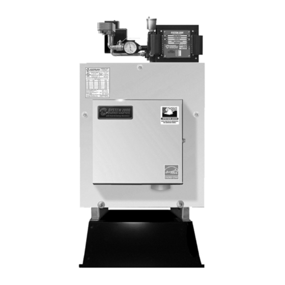
Page 7: System 2000 Frontier Boiler
When energy recovery is complete and the Boiler has been cooled off, the Digital Manager turns off the system and waits for another thermostat (or tank aquastat) to call for heat. SYSTEM 2000 runs the burner only when you need heat and delivers that heat only where you need heat. -
Page 8: Receiving And Unpacking
6. MONITOR RETURN TEMPERATURE: The Manager continually senses the return temperature and will turn off the zone outputs if the return temperature drops below 120 F (130 F if Option Switch #1 is ON). With the zone outputs closed, the boiler water will quickly reheat and once the return temperature reaches 140 F (150 F if Option Switch #1 is ON), then the Manager will reopen the zone valves. -
Page 9: Clearance For Cleaning And Service
NOTICE: Do not install on carpeting. Place the unit as near to the chimney or vent as possible allowing clearance for front cleaning and service as shown in Figure 1B. If not using an Energy Kinetics supplied stand, provide a solid, level, smooth, foundation with clearance for door opening and service. -
Page 10: Chimney Connector
The metal chimney liner diameter and length should be as recommended by the metal chimney liner manufacturer. Corrugated metal liners should be at least 5" diameter for EK-1 and 6" diameter for EK-2. Call Energy Kinetics for details on metal liners. -
Page 11: B-Vent Chimney
Gas Heat System 2000 boilers and Type L gas vent must be installed in strict compliance with all State and Local Codes and with the regulations of the authorities having jurisdiction, which may differ from and which take precedence over these instructions or the vent manufacturer’s instructions. -
Page 12: Gas Burner Mounting
EK-1 Boilers are shipped from the factory preset for 120,000 Btu/Hr firing rate and EK-2 Boilers are shipped from the factory preset for 200,000 Btu/Hr firing rate. The SYSTEM 2000 Boiler can be fired over a range of firing rates to suit the needs of the application. -
Page 13: General Assembly
200 feet GENERAL ASSEMBLY Assembly of various packaged units is illustrated throughout this manual. The use of non-Energy Kinetics supplied pump, controls and accessories should follow good practices. The diagrams and locations presented in the manual are recommended. WARNING: Boiler shall be installed such that the gas ignition system components are protected from water (dripping, spraying, rain, etc.) during appliance operation and service (circulator replacement, control replacement,... - Page 14 Premier Option: Return Supply Supply Return Ball & Ball Purge Valves T&P Gauge System Circ Bypass Main/System Circ High Limit Feedwater SYSTEM 2000 ENERGY MANAGER Connection T H ERM OSTAT HEATING HOT WATER 24VAC CHIMNEYLESS O NLY INDUCER ERGY B URNER...
-
Page 15: Piping
ZONE CONTROL BY VALVE: The SYSTEM 2000 Boiler is designed to provide multi-zone control of the heating system. Energy Kinetics recommends and supplies two wire, full port, 24-volt zone valves for control of each heating zone. A system with a single heating zone still requires a zone valve to provide control for preheat of unit and to maintain minimum temperature during operation. -
Page 16: Filling With Water, Venting, And Purging
When a home is winterized by draining all domestic water piping, then the SYSTEM 2000 Boiler must be protected. It is not recommended to drain the SYSTEM 2000 Boiler, because introducing air into the boiler can cause rusting inside the boiler shell and also because the Energy Converter has a spiral water passage that cannot be completely drained of water. -
Page 17: Line Voltage Wiring Diagrams
LINE VOLTAGE WIRING DIAGRAMS NEUTRAL OUTPUT CABLE FROM 120 VAC POWER IN GROUND DIGITAL MANAGER FIELD WIRING RIGHT SIDE USE COPPER CONDUCTORS ONLY (ORANGE) -ZHW TRANSFORMER (GREEN) -24 V POWER LEADS (RED) -IND (BLACK) Black White Line (WHITE) (Hot) (Neutral) Voltage (BLUE) -CIRC... -
Page 18: Electrical Connection - Line Voltage
System 2000 requires 120 VAC. The supply voltage must be within 108 VAC min / 132 VAC max for reliable operation of the boiler and the Manager. An easy way to check the supply voltage is to plug a voltmeter in at the service outlet located on the side of the system junction box. - Page 19 LOW VOLTAGE WIRING DIAGRAM FIELD WIRING FACTORY WIRING Loop Circ Relay *Field Wiring terminated to input terminal A1 and to output terminal 24VAC are to Connected to Z11 be wired into the open lugs provided at those locations. HOT WATER TANK or ADDITIONAL ZONE ZONE 4 ZONE 1...
- Page 20 Five Zone Display Manager The Display Manager is an Energy Manager that is equipped with an LCD display , and four pushbutton keys . With the exception of the Fuel Type (oil/gas) and Venting (chimney/inducer) options, all setup options are selected through option screens via the display and keys .
- Page 21 Dip Switch Settings Set dip switches for Fuel type: Oil or Gas and Vent type: Chimney or Inducer INSTALLATION TIPS Dip Switches “OFF” Display Managers are shipped Bottom edge of Energy Manager NOTE: “ON” is DOWN position with both dip switches “OFF” (set for an oil system with a chimney).
- Page 22 EXPANDED ENERGY MANAGER ZONE OUTPUTS ZONE INPUTS 15 Zone Manager 24VAC (THERMOSTATS) Figure 4C (ZONE VALVES OR ZONE CIRC RELAYS) ZONE 14 ZONE 14 ZONE 13 ZONE 13 ZONE 12 ZONE 12 ZONE 11 ZONE 11 ZONE 10 ZONE 10 ZONE 9 ZONE 9 ZONE 8...
- Page 23 Auto Reset High Limit DualGard Model: 2450-1 Frontier Boiler Auto Reset LWCO F Differential (215 /205 Energy Kinetics PN: 10-0596 Manual Reset Lock Out Temp F Manual Reset Fixed Max F Auto Reset High Limit Frontier Boiler Auto Reset High Limit Aquastat...
-
Page 24: Start Up Procedure
Close the main manual gas valve and turn the combination gas valve knob to ON. c. Turn on power to System 2000 boiler and adjust a thermostat to call for heat. d. Burner motor will start. The burner control will run for 30 seconds (pre-purge), and then start the ignitor. -
Page 25: The Air-Free Method Of Measuring Co
The AIR-FREE METHOD of MEASURING CO Air-free measurement of CO takes account of the amount of excess air by incorporating an adjustment to the as- measured ppm value, thus simulating air-free (oxygen-free) conditions in the combustion gases. To do this, a reading of oxygen (O2) or carbon dioxide (CO2) percentage is taken from the combustion gases along with the as-measured CO reading. - Page 26 Energy Manager Operation WARNING: Do Not Jump! If you apply 24VAC to any Energy sensor lead with the sensor connected to the Manager, you will burn out both the sensor and the Manager in less than a second. NOTE: The Manager cannot lockout the primary control on the burner.
-
Page 27: Output Side
Energy Manager Check Troubleshooting The burner will not run unless there is a call for heat (thermostat call) or a call for domestic hot water (tank aquastat). Note: Do NOT Jumper Connections or Apply Voltage to Test the Manager. Follow these simple steps: Look at the Manager See what it is telling you is supposed to be happening. -
Page 28: 2-Minute Energy Manager Diagnostic
1, 2, and 3. If problem persists, call technical support or replace manager. Note malfunction on warranty tag and return manager to Energy Kinetics. If problem goes away, there is a problem with the output wiring –... -
Page 29: Additional Manager Tests
Additional Manager Tests Perform the following tests ONLY if you have any of the following: Case 1) Zones heating intermittently Case 2) E140 or E150 displayed WITHOUT a burner lockout Case 3) E100 or E190 displayed If you have a burner lockout, troubleshoot as any conventional burner lockout. Case 1: Zones heating intermittently Step 1: Have all connected thermostats including hot water aquastat call continuously for at least 10 minutes. -
Page 30: Line Voltage Relays
Line Voltage System 2000 requires 120 VAC. The supply voltage must be within 108 VAC min / 132 VAC max for reliable operation of the boiler and the Manager. An easy way to check the supply voltage is to plug a volt meter in at the service outlet located on the system junction box. - Page 31 TROUBLESHOOTING with the ENERGY MANAGER Display Manager Error Codes and Faults An error code on the display indicates that Display Manager has detected a problem. E100: Temperature sensor is not working properly. This indicates that the Manager is in service board mode. Circulator and inducer run constantly , burner runs off the high limit aquastat.
-
Page 32: So Caution Should Be Used In Systems Without Antifreeze.annual Tune Up & Inspection
F and zone will get heat on call. IF A PLUG-IN RELAY FAILS: Replace with spare relay. If spare is not available, temporarily install a relay with 24VAC coil and 120VAC contacts. Contact Energy Kinetics for connection details. EMERGENCY HEAT WITHOUT ENERGY MANAGER or RELAY BOARD (Temporary Operation Only –... -
Page 33: Step 3 Inspect Flue Passage
ANNUAL TUNE UP & INSPECTION Please refer to installation manual and burner manual for complete details and for burners other than EZ-Gas. Step 1 Initial Test (Draft Loss & CO Air box cover must be in place before testing 1. Remove 1/8” brass plug from the “over fire” test port (2) next to the burner and the flue box (1) next to the puff switch. -
Page 34: Annual Tune Up & Inspection
Close the main manual gas valve and turn the combination gas valve knob to c. Turn on power to System 2000 boiler and adjust a thermostat to call for heat. d. Burner motor will start. The burner control will run for 30 seconds (pre-purge), then start the ignitor. -
Page 35: Replacement Parts
The combustion chamber is of high quality material and will normally not need to be replaced. A replacement chamber, if required, is available from Energy Kinetics. The proper part number for the Frontier chamber must be specified when ordering. For interim operation, the unit may be run without a combustion chamber if necessary. Ensure that the burner head is protected by the amulet, wet pack or a similar material. - Page 36 Replacement Parts Obtain replacement parts from your local Energy Kinetics dealer. Contact Energy Kinetics at 800-323-2066 or www.energykinetics.com for help locating your nearest authorized dealer. ITEM Frontier Frontier DESCRIPTION PART NO. PART NO. 10-0710 10-0810 Combustion Chamber 10-0394 10-0395 Energy Converter (Frontier)
- Page 37 In the event that such pressure vessel is found to be defective in material or workmanship during the first ten years, Energy Kinetics will repair or replace the pressure vessel at its option and include a labor allowance per the published schedule.
- Page 38 The End User is required to make available for inspection by Energy Kinetics or its representative, the parts claimed to be defective and, if requested by Energy Kinetics, to ship said parts prepaid to Energy Kinetics at the above address for inspection or repair. In addition, the homeowner agrees to make all reasonable efforts to settle any disagreement arising in connection with this claim before resorting to legal remedies in courts.
Need help?
Do you have a question about the System 2000 and is the answer not in the manual?
Questions and answers
bleed air from fuel line
To bleed air from the fuel line on an ENERGY KINETICS System 2000 oil burner:
1. Gather Tools: You will need a 3/8-inch wrench, a small container to catch oil, and optionally, a small piece of 1/4-inch rubber tubing to make the process easier.
2. Locate the Bleed Fitting: Find the bleed fitting on the oil pump. It is on the left side of the burner where the oil line connects. It will have a hex with a small hose barb protruding.
3. Prepare to Catch Oil: Position the container directly below the bleed fitting to catch any oil or air that comes out.
4. Loosen the Fitting: Use the wrench to loosen the hex on the bleed fitting. This will release a little oil and possibly air bubbles.
5. Reset the Burner: Press the reset button on the burner to start it. Let it run while keeping the bleed fitting open until you see a steady stream of oil without air bubbles.
6. Tighten the Fitting: Once the air is fully purged and oil flows steadily, tighten the bleed fitting securely.
7. Check Operation: Ensure the burner is operating normally after the process.
This answer is automatically generated