
Related Manuals for CSZ Blanketrol III 233


Summary of Contents for CSZ Blanketrol III 233
- Page 1 Operation and Technical Manual Model 233 Hyper-Hypothermia System Cincinnati Sub-Zero Products, LLC 12011 Mosteller Road Cincinnati, Ohio 45241, U.S.A. www.cszmedical.com...
-
Page 2: Operation And Technical Manual Blanketrol Iii, Model
OPERATION AND TECHNICAL MANUAL BLANKETROL III, Model 233 ® BLANKETROL is a registered trademark of Cincinnati Sub Zero Products, LLC, Cincinnati, Ohio USA. © Copyright 2017, Cincinnati Sub-Zero Products, LLC All rights reserved. Manual 57299 Rev. D ECN: M1708-5362 Page 2 of 128... - Page 3 OPERATION AND TECHNICAL MANUAL BLANKETROL III, Model 233 Symbol Definitions Read Operation Instructions and Manual Gradient Temperature Set Gradient 10˚ C Before Operating Variable INCREMENT DECREMENT Automatic Manual (Increase (Decrease Smart Control Control Temperature) Temperature) Mode Silence Water Patient Monitor Test Indicators Alarm Temperature...
- Page 4 Contamination can affect patient’s health, i.e. skin irritation/rash may result. Use only YSI 400 Series, or equivalent, probes on CSZ equipment (refer to Table (6-8)). Failure to do this will cause incorrect temperature readings and may result in inadequate/inappropriate treatment.
- Page 5 OPERATION AND TECHNICAL MANUAL BLANKETROL III, Model 233 WARNING Do not use the BLANKETROL III system in the presence of flammable anesthetics. Risk of explosion can result. Remove the BLANKETROL III from service if the outer casing or membrane control panel is cracked or internal components are exposed.
- Page 6 Improper repair can result in damage to the BLANKETROL III system and patient injury. No modification of this equipment is allowed without prior, written authorization from CSZ. Failure to do so may result in damage to the BLANKETROL III system and patient injury. ...
- Page 7 Users should not use cleaning or decontamination methods different from those recommended by CSZ without first checking with CSZ that the proposed methods will not damage the equipment. Working with electronic boards, plugs, and cables requires delicate handling. Proper electrostatic discharge (ESD) procedures should be followed during replacement of any electronic board.
-
Page 8: Table Of Contents
OPERATION AND TECHNICAL MANUAL BLANKETROL III, Model 233 Table of Contents TECHNICAL HELP TELEPHONE 1-800-989-7373 ..................11 BEFORE YOU CALL FOR SERVICE........................11 IN-WARRANTY REPAIR AND PARTS ....................... 11 RECEIVING INSPECTION ............................. 11 IMPORTANT SAFETY INFORMATION ......................11 SECTION 1. INTRODUCTION..........................12 1-0. - Page 9 OPERATION AND TECHNICAL MANUAL BLANKETROL III, Model 233 4-2. MAINTENANCE OF THE WATER RESERVOIR .................. 72 4-2.1. Draining the Reservoir ......................... 75 4-2.2. Replenishing the Reservoir ........................76 4-3. MAINTENANCE OF THE WATER FILTER ..................76 4-4. MAINTENANCE OF THE CONDENSER AND GRILL ................. 77 MAINTENANCE OF THE BLANKETROL III EXTERIOR –...
- Page 10 OPERATION AND TECHNICAL MANUAL BLANKETROL III, Model 233 FIGURES AND TABLES FIGURE 1-1. BLANKETROL III - FRONT VIEW ......................15 FIGURE 1-2. BLANKETROL III - RIGHT SIDE ....................... 17 FIGURE 1-3. BLANKETROL III - REAR VIEW ....................... 19 FIGURE 1-4.A. BLANKETROL III - MEMBRANE CONTROL PANEL (ENGLISH) ............ 21 FIGURE 4-1.
-
Page 11: Technical Help Telephone 1-800-989-7373
To return defective parts or units, first obtain a Returned Materials Authorization (RMA) number from our Medical Technical Service department. All returns should be made using CSZ-issued shipping cartons. RECEIVING INSPECTION After unpacking the BLANKETROL III System, be sure to inspect the system for concealed damage. -
Page 12: Section 1. Introduction
1-1. GENERAL DESCRIPTION OF THIS MANUAL This manual describes the operation, maintenance, and service of the CSZ BLANKETROL III System. Section one describes the physical and functional characteristics of the BLANKETROL III System. Section two describes how to prepare the BLANKETROL III System for general use. - Page 13 OPERATION BLANKETROL III, Model 233 OPERATION AND TECHNICAL MANUAL Distilled water is heated or cooled and pumped from the unit to a blanket. The blanket* rests under and/or on top of the patient and is designed so that the water circulates through the blanket and returns to the unit.
-
Page 14: Physical Description Of The Blanketrol Iii Unit
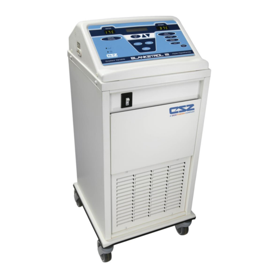
OPERATION BLANKETROL III, Model 233 OPERATION AND TECHNICAL MANUAL 1-3. PHYSICAL DESCRIPTION OF THE BLANKETROL III UNIT See Section (7.) for specifications and certifications of the BLANKETROL III. 1-3.1. External Features - Front View The external features in Figure (1-1.) of the BLANKETROL III unit are described as follows: The control panel is composed of pressure sensitive touch switches, nine LED indicators, a liquid crystal display, and two LED displays. -
Page 15: Figure 1-1. Blanketrol Iii - Front View
OPERATION BLANKETROL III, Model 233 OPERATION AND TECHNICAL MANUAL FIGURE 1-1. BLANKETROL III - FRONT VIEW Page 15 of 128... -
Page 16: 1-3.2. External Features - Right Side View
OPERATION BLANKETROL III, Model 233 OPERATION AND TECHNICAL MANUAL 1-3.2. External Features – Right Side View The external features in Figure (1-2.) of the BLANKETROL III unit are described as follows: The water flow indicator is a paddle wheel immersed in the path of the circulating water with a window to the outside. -
Page 17: Figure 1-2. Blanketrol Iii - Right Side
OPERATION BLANKETROL III, Model 233 OPERATION AND TECHNICAL MANUAL FIGURE 1-2. BLANKETROL III - RIGHT SIDE Page 17 of 128... -
Page 18: 1-3.3. External Features - Rear View
OPERATION BLANKETROL III, Model 233 OPERATION AND TECHNICAL MANUAL 1-3.3. External Features – Rear View The external features in Figure (1-3.) of the BLANKETROL III unit are described as follows: The specification label outlines the BLANKETROL III unit's electrical requirements and displays the serial and model numbers of the unit. -
Page 19: Figure 1-3. Blanketrol Iii - Rear View
OPERATION BLANKETROL III, Model 233 OPERATION AND TECHNICAL MANUAL FIGURE 1-3. BLANKETROL III - REAR VIEW Page 19 of 128... -
Page 20: 1-3.4. Description Of The Blanketrol Iii Membrane Control Panel
OPERATION BLANKETROL III, Model 233 OPERATION AND TECHNICAL MANUAL 1-3.4. Description of the BLANKETROL III Membrane Control Panel The membrane control panel as shown in Figure (1-4.A.) for English is composed of pressure sensitive touch switches and LED displays. The membrane control panel is divided into the following sections: The green LED display labeled WATER shows the water temperature in the BLANKETROL III equipment. -
Page 21: Required Accessories
OPERATION BLANKETROL III, Model 233 OPERATION AND TECHNICAL MANUAL FIGURE 1-4.A. BLANKETROL III - MEMBRANE CONTROL PANEL (English) 1-4. REQUIRED ACCESSORIES Operation of the BLANKETROL III System requires the use of the blanket(s) designed to circulate warm or cool distilled water, a connecting hose with quick-disconnect male and female fittings and, if any of the automatic modes are to be utilized, a 400 Series thermistor probe. - Page 22 OPERATION BLANKETROL III, Model 233 OPERATION AND TECHNICAL MANUAL MANUAL CONTROL MODE the BLANKETROL III System does not read the patient’s temperature. Because of this, special care must be taken to monitor the patient’s temperature. As in all cases, the patient's skin integrity must be closely monitored. In AUTO CONTROL MODE, the operator specifies the patient’s Set Point temperature.
-
Page 23: 1-5.2. Heating System
OPERATION BLANKETROL III, Model 233 OPERATION AND TECHNICAL MANUAL GRADIENT VARIABLE MODE. SMART MODE can be turned on and off at will, and is indicated as such by the green LED next to the SMART MODE button. As in all cases, the patient's skin integrity must be closely monitored. -
Page 24: 1-5.5. Temperature Safety Control System
OPERATION BLANKETROL III, Model 233 OPERATION AND TECHNICAL MANUAL The water circulates through the blanket(s) and returns to the unit. The water then passes through the water flow indicator, through the water filter, through the flow switch, and returns to the circulating reservoir to be re-heated or re-cooled and then recycled. -
Page 25: 1-5.6. Usb Port Operation
3.6°F), the back-up safety device shuts off the unit, the Status Display indicates LOW LIMIT REMOVE FROM SERVICE, and the trouble alarm sounds. 1-5.6. USB Port Operation Refer to CSZ manual 57059 for instructions and usage of the BLANKETROL III Data Export Software. CAUTION ... -
Page 26: Section 2. General Preparation Of The Blanketrol Iii System
OPERATION BLANKETROL III, Model 233 OPERATION AND TECHNICAL MANUAL SECTION 2. GENERAL PREPARATION OF THE BLANKETROL III SYSTEM 2-1. INTRODUCTION This section describes the procedures to prepare the BLANKETROL III System for general use. This entails unpacking the shipment, arranging all the equipment for the first time, and completing a test routine. - Page 27 OPERATION BLANKETROL III, Model 233 OPERATION AND TECHNICAL MANUAL Examine the power cord for cuts or exposed wires and the power plug for bent or missing prongs. Review Section (1-3.) to identify the features of the BLANKETROL III System. Collect and arrange the following equipment and supplies: Hyper-hypothermia blanket(s) described in Section (1-4.) and listed in Table (6-8.).
-
Page 28: 2-3.2. Completing A System Test Routine
OPERATION BLANKETROL III, Model 233 OPERATION AND TECHNICAL MANUAL Push the male coupling until it SNAPS into position 10. Gently pull the connecting hose to assure a positive connection Check that the blanket is lying flat and that the connecting hose to the unit is not twisted or pinched. - Page 29 OPERATION BLANKETROL III, Model 233 OPERATION AND TECHNICAL MANUAL Press the MONITOR ONLY button. 1. The LED in the corner of the MONITOR ONLY switch illuminates 2. An alarm sounds. 3. The Status Displays CHECK PROBE because no probe is attached. Press the TEMP SET switch.
- Page 30 OPERATION BLANKETROL III, Model 233 OPERATION AND TECHNICAL MANUAL CAUTION Use distilled water only. Do Not Use De-Ionized water. De-Ionized water may cause corrosion to plumbing system components. Do Not Use Tap Water. Minerals and deposits can clog plumbing system components. ...
- Page 31 OPERATION BLANKETROL III, Model 233 OPERATION AND TECHNICAL MANUAL The microprocessor board beeps each time it is pressed. The Set Point display changes; the numbers move down the scale. The longer the button is pressed the faster the digits change. When the button is released and repressed, the digits once again change slowly and then increase in speed.
- Page 32 OPERATION BLANKETROL III, Model 233 OPERATION AND TECHNICAL MANUAL The microprocessor board beeps. The LED in the corner of the button illuminates. The Status Display returns to set temperature mode. Press the Up arrow or the Down arrow so that the Set point displays 37°C (98.6°F). Set the patient probe to a temperature reading between 30°C –...
- Page 33 OPERATION BLANKETROL III, Model 233 OPERATION AND TECHNICAL MANUAL The above depends upon the relationship of the patient temperature to the Set Point temperature. Note that the Set Point may be displayed in Fahrenheit. The pump is activated. The heater or compressor may be activated. The water flow indicator on the right side panel begins to move.
- Page 34 OPERATION BLANKETROL III, Model 233 OPERATION AND TECHNICAL MANUAL Press the Up arrow or Down arrow to change the gradient variable offset to the desired value. The microprocessor board beeps. The offset in the Status Display changes. Press the GRADIENT VARIABLE button. The microprocessor board beeps.
-
Page 35: Unit And Patient Related Precautions
OPERATION BLANKETROL III, Model 233 OPERATION AND TECHNICAL MANUAL The above depends upon the relationship of the blanket water temperature to the Set Point temperature. Note that the Set Point may be displayed in Fahrenheit. The pump is activated. The heater or compressor may be activated. The water flow indicator on the right side panel begins to move. -
Page 36: Patient Preparation And Bedside Care
Contamination can affect patient’s health, i.e. skin irritation/rash may result. Use only YSI 400 Series, or equivalent, probes on CSZ equipment (refer to Table (6-8)). Failure to do this will cause incorrect temperature readings and may result in inadequate/inappropriate treatment. - Page 37 OPERATION BLANKETROL III, Model 233 OPERATION AND TECHNICAL MANUAL WARNING Basic static electricity or ESD training should include an introduction to the physics of electrostatic charge, the voltage levels that can occur in normal practice and the damage that can be done to electronic components if equipment is touched by an operator who is electrostatically charged.
- Page 38 BLANKETROL III system and patient injury. No modification of this equipment is allowed without prior, written authorization from CSZ. Failure to do so may result in damage to the BLANKETROL III system and patient injury. ...
- Page 39 Users should not use cleaning or decontamination methods different from those recommended by CSZ without first checking with CSZ that the proposed methods will not damage the equipment. Working with electronic boards, plugs, and cables requires delicate handling. Proper electrostatic discharge (ESD) procedures should be followed during replacement of any electronic board.
-
Page 40: Section 3. Operating The Blanketrol Iii System
OPERATION BLANKETROL III, Model 233 OPERATION AND TECHNICAL MANUAL SECTION 3. OPERATING THE BLANKETROL III SYSTEM 3-1. INTRODUCTION This section describes how to operate the BLANKETROL III System in order to control a patient's temperature. First, collect the equipment and prepare the patient. Second, decide which mode of operation to use. - Page 41 OPERATION BLANKETROL III, Model 233 OPERATION AND TECHNICAL MANUAL CAUTION Use distilled water only. Do Not Use De-Ionized water. De-Ionized water may cause corrosion to plumbing system components. Do Not Use Tap Water. Minerals and deposits can clog plumbing system components. ...
- Page 42 OPERATION BLANKETROL III, Model 233 OPERATION AND TECHNICAL MANUAL The hyper-hypothermia blanket may be pre-cooled or pre-warmed before positioning the patient. To do so, operate the system in MANUAL CONTROL MODE for a few minutes. Place the patient on the hyper-hypothermia blanket. CAUTION ...
-
Page 43: Operating The Blanketrol Iii System In Auto Control Mode
OPERATION BLANKETROL III, Model 233 OPERATION AND TECHNICAL MANUAL Operating in GRADIENT VARIABLE SMART MODE is described in Section (3-9.). Operating in MONITOR ONLY MODE is described in Section (3-10.). NOTE: The maximum contact surface temperature is 41°C. NOTE: If at any time, power is removed from the unit without actuating the power switch (I/O switch) a power fail alarm will activate and the Power fail symbol LED located on the membrane control panel will flash. - Page 44 OPERATION BLANKETROL III, Model 233 OPERATION AND TECHNICAL MANUAL Connect the 400 Series probe to the 1/4 inch receptacle on the right side of the unit. If using a disposable probe, a Connecting cable is needed to connect the probe to the BIII.
- Page 45 OPERATION BLANKETROL III, Model 233 OPERATION AND TECHNICAL MANUAL AUTO SETPT 37.0 C * (”XXXXXX” represents “HEATING” or “COOLING”.) The above depends upon the relationship of the patient temperature to the Set Point temperature. Note that the Set Point may be displayed in Fahrenheit.
-
Page 46: Operating The Blanketrol Iii System In Manual Control Mode
OPERATION BLANKETROL III, Model 233 OPERATION AND TECHNICAL MANUAL 3-4. OPERATING THE BLANKETROL III SYSTEM IN MANUAL CONTROL MODE WARNING A physician's order is required for setting blanket temperature and use of equipment. At least every 20 minutes, or as directed by physician, check patient's temperature and skin integrity of areas in contact with blanket;... - Page 47 OPERATION BLANKETROL III, Model 233 OPERATION AND TECHNICAL MANUAL The microprocessor board beeps. The LED in the corner of the button illuminates. The BLANKET/WATER display shows the actual temperature of the water in the BLANKETROL III equipment. The Status Display shows: * XXXXXX WATER MANUAL SETPT 37.0 C...
-
Page 48: Operating The Blanketrol Iii System In Manual Control Mode With The Addition Of The Patient Probe
OPERATION BLANKETROL III, Model 233 OPERATION AND TECHNICAL MANUAL 3-5. OPERATING THE BLANKETROL III SYSTEM IN MANUAL CONTROL MODE WITH THE ADDITION OF THE PATIENT PROBE WARNING A physician's order is required for setting blanket temperature and use of equipment. At least every 20 minutes, or as directed by physician, check patient's temperature and skin integrity of areas in contact with blanket;... -
Page 49: Operating The Blanketrol Iii System In Gradient 10C Mode
OPERATION BLANKETROL III, Model 233 OPERATION AND TECHNICAL MANUAL NOTE: IN ORDER TO CHANGE FROM AUTOMATIC CONTROL MODE TO ANOTHER CONTROL MODE, FIRST PRESS THE “TEMP SET” BUTTON, AND THEN SELECT THE OPERATING MODE OF CHOICE. CONTROL MODE to MONITOR ONLY MODE, simply In order to change from MANUAL press the Monitor Only button. - Page 50 OPERATION BLANKETROL III, Model 233 OPERATION AND TECHNICAL MANUAL The switch illuminates green. The microprocessor board goes through self-test. The Status Display flashes CHECK SETPT. Consult the physician's orders to determine the desired patient Set Point temperature. As a safety precaution, the desired patient Set Point can only be set between 30°C - 40°C (86°F - 104°F) to operate in GRADIENT 10C mode.
- Page 51 OPERATION BLANKETROL III, Model 233 OPERATION AND TECHNICAL MANUAL The pump is activated. The heater or compressor may also be activated. The Water Flow indicator on the right side panel begins to move. The water moves from the unit to the blanket and returns to the unit. Check the water flow indicator to confirm that the water is circulating.
-
Page 52: Operating The Blanketrol Iii Unit In Gradient 10C Smart Mode
OPERATION BLANKETROL III, Model 233 OPERATION AND TECHNICAL MANUAL 3-7. OPERATING THE BLANKETROL III UNIT IN GRADIENT 10C SMART MODE WARNING A physician's order is required for setting blanket temperature and use of equipment. At least every 20 minutes, or as directed by physician, check patient's temperature and skin integrity of areas in contact with blanket;... - Page 53 OPERATION BLANKETROL III, Model 233 OPERATION AND TECHNICAL MANUAL Consult the physician's orders to determine the desired patient Set Point temperature. As a safety precaution, the desired patient Set Point can only be set between 30°C - 40°C (86°F - 104°F) to operate in GRADIENT 10C SMART MODE. Use the C/F button to choose the desired temperature scale.
-
Page 54: Operating The Blanketrol Iii System In Gradient Variable Mode
OPERATION BLANKETROL III, Model 233 OPERATION AND TECHNICAL MANUAL The LED on the SMART button illuminates. Check the Water Flow indicator to confirm that the water is circulating. Touch the hyper-hypothermia blanket to confirm that the blanket is heating/cooling. To make any changes in the control settings, press the TEMP SET button and begin again. - Page 55 OPERATION BLANKETROL III, Model 233 OPERATION AND TECHNICAL MANUAL CAUTION If device is set to operate in any Automatic mode, the device will shut down and activate the CHECK PROBE alarm if the patient temperature falls below 30.0°C (86°F). Patient temperature must rise above 30.0°C (86°F) before restarting the device in Automatic mode.
- Page 56 OPERATION BLANKETROL III, Model 233 OPERATION AND TECHNICAL MANUAL The Status Display shows a gradient variable. Press the Up arrow or Down arrow to change the gradient variable offset to the desired value. The microprocessor board beeps. The Set Point temperature in the Status Display changes. Press the GRADIENT VARIABLE button.
-
Page 57: Operating The Blanketrol Iii System In Gradient Variable Smart Mode
OPERATION BLANKETROL III, Model 233 OPERATION AND TECHNICAL MANUAL consult the list of display messages in Section (3-12.). If at any time the unit sounds an alarm and the Status Display flashes a message, make the changes indicated. To turn off the unit or discontinue hyper-hypothermia treatment, proceed as described in Section (3- 11.). - Page 58 OPERATION BLANKETROL III, Model 233 OPERATION AND TECHNICAL MANUAL After arranging the equipment as described in Section (3-2.), proceed as follows: Check the placement of the 400 Series probe in or on the patient. Connect the probe to the 1/4 inch receptacle on the right side of the unit. Press the power switch to the “I”...
- Page 59 OPERATION BLANKETROL III, Model 233 OPERATION AND TECHNICAL MANUAL Press the GRADIENT VARIABLE button. The microprocessor board beeps. The LED in the corner of the switch illuminates. The PATIENT display shows the patient's actual temperature. The WATER display shows the actual temperature of the water in the BLANKETROL III equipment.
-
Page 60: Operating The Blanketrol Iii System In Monitor Only Mode
OPERATION BLANKETROL III, Model 233 OPERATION AND TECHNICAL MANUAL To turn off the unit or discontinue hyper-hypothermia treatment, proceed as described in Section (3- 11.). NOTE: IN ORDER TO CHANGE FROM GRADIENT VARIABLE SMART MODE TO ANOTHER CONTROL MODE, FIRST PRESS THE “TEMP SET” BUTTON, AND THEN SELECT THE OPERATING MODE OF CHOICE. -
Page 61: Concluding Hyper-Hypothermia Treatment
OPERATION BLANKETROL III, Model 233 OPERATION AND TECHNICAL MANUAL The LED in the corner of the button illuminates. The Patient display shows the patient's temperature. The Status Display indicates MONITOR ONLY and the selected temperature scale. To make any changes in the control settings, press the TEMP SET button and begin again. -
Page 62: Status Display Messages
OPERATION BLANKETROL III, Model 233 OPERATION AND TECHNICAL MANUAL For Single-Patient Use blankets, dispose of the blanket per hospital/institution policy/protocol. 3-12. STATUS DISPLAY MESSAGES The Status Display located in the center of the BLANKETROL III unit membrane control panel reports the operating status of the unit or indicates changes the operator must make. The Status Display can show different messages to guide the operator. - Page 63 OPERATION BLANKETROL III, Model 233 OPERATION AND TECHNICAL MANUAL This message is displayed on the top line when the BLANKETROL III is HEATING PATIENT heating the patient. This message is displayed on the top line when the BLANKETROL III is COOLING PATIENT cooling the patient.
- Page 64 The unit cannot be used again until it is serviced. The seven-segment displays (“WATER” and “PATIENT”) will both be blank during this condition. Contact CSZ Technical Service. This message occurs when the thermostatic snap disc has opened or is disconnected, or when the reservoir temperature has exceeded 46°C ...
- Page 65 “EE01” “REMOVE FROM SERVICE” will reappear in the Status Display and the trouble alarm will sound. The unit cannot be used again until it is serviced. Contact CSZ Technical Service. This message will be displayed if the water temperature sensor is open or shorted.
- Page 66 OPERATION BLANKETROL III, Model 233 OPERATION AND TECHNICAL MANUAL This message is displayed to alert the operator when the probe needs to be checked. For instance: 1. If the probe is operating outside of the normal operating range of 30.0°C – 43.5°C (86°F to 110.3°F) during any automatic mode, this message will be displayed.
- Page 67 OPERATION BLANKETROL III, Model 233 OPERATION AND TECHNICAL MANUAL This message occurs when the float switch senses that the water in the reservoir is below a preset level or the float switch is defective. The trouble alarm sounds, the seven-segment displays will be blank, the low water symbol LED will flash, and the heater, compressor and pump will turn off.
- Page 68 OPERATION BLANKETROL III, Model 233 OPERATION AND TECHNICAL MANUAL This message displays the total number of hours of operation until the next required PM. To display this message, simultaneously press SILENCE ALARM and TEMP SET buttons. Note: 1. Maintenance should be performed at least quarterly or when indicated HOURS UNTIL SERVICE by 500 hour PM notification, whichever occurs first.
-
Page 69: Section 4. General Maintenance Of The Blanketrol Iii System
MAINTENANCE BLANKETROL III, Model 233 OPERATION AND TECHNICAL MANUAL SECTION 4. GENERAL MAINTENANCE OF THE BLANKETROL III SYSTEM 4-1. INTRODUCTION This section describes the general requirements maintenance personnel should complete on a regular basis so that the BLANKETROL III System continues to operate within the manufacturers’ allowable tolerances. -
Page 70: 4-1.1. Test Equipment Required
The following test equipment is required to perform the preventive maintenance/functional check- out procedures: • CSZ's model TFRW 86171 Trimatic (Temperature Tester, Flow Meter, Resistance Tester) - Need Probe Extension Cable #TM-4A (Part # 39005) - Need Hose Assembly #TM-6 (Part # 91802) •... -
Page 71: Figure 4-1. Blanketrol Iii Maintenance Checklist
MAINTENANCE BLANKETROL III, Model 233 OPERATION AND TECHNICAL MANUAL FIGURE 4-1. BLANKETROL III MAINTENANCE CHECKLIST REQUIRED PREVENTIVE MAINTENANCE CHECKLIST (Quarterly or when indicated by 500 hour PM notification) BLANKETROL III - Model 233 Hospital Control No. Serial Number Check When Completed ... -
Page 72: Maintenance Of The Water Reservoir
For safe handling and use of chemicals follow manufacturer guidelines. Users should not use cleaning or decontamination methods different from those recommended by CSZ without first checking with CSZ that the proposed methods will not damage the equipment. - Page 73 MAINTENANCE BLANKETROL III, Model 233 OPERATION AND TECHNICAL MANUAL Note: The duration indicated in the CCC chart is meant to begin when the circulating water reaches the temperature indicated in the CCC chart. Drain the unit as instructed in Step #1. Rinse the unit three (3) times as described in Steps 4-6.
- Page 74 MAINTENANCE BLANKETROL III, Model 233 OPERATION AND TECHNICAL MANUAL If unit is to be returned to service, replenish reservoir(s) with the appropriate volume of distilled water. If unit is being placed in dry storage, continue with procedure. When all fluid has been removed from the unit, disconnect the drain hose(s) and wipe unit clean.
-
Page 75: 4-2.1. Draining The Reservoir
MAINTENANCE BLANKETROL III, Model 233 OPERATION AND TECHNICAL MANUAL 4-2.1. Draining the Reservoir CAUTION Always drain the BLANKETROL III to a sanitary drain because bio-contaminants may be present in the unit’s water supply. Collect these items: An empty container to drain the water into that can hold at least 3 gallons (11.4 liters). -
Page 76: 4-2.2. Replenishing The Reservoir
MAINTENANCE BLANKETROL III, Model 233 OPERATION AND TECHNICAL MANUAL If any other maintenance/repair is to be completed, go to the appropriate section, e.g., cleaning the water filter. If not, go to Section (4-2.2.) to replenish the reservoir. 4-2.2. Replenishing the Reservoir Check that the drain hose is disconnected. -
Page 77: Maintenance Of The Condenser And Grill
MAINTENANCE BLANKETROL III, Model 233 OPERATION AND TECHNICAL MANUAL WARNING The repair, calibration, and servicing of the BLANKETROL III should be performed by qualified Medical Equipment Service Technicians, Certified Biomedical Electronics Technicians, or Certified Clinical Engineers familiar with good repair practices for servicing medical devices, and in accordance with instructions contained in this manual. -
Page 78: Maintenance Of The Blanketrol Iii Exterior - Cleaning Instructions
MAINTENANCE BLANKETROL III, Model 233 OPERATION AND TECHNICAL MANUAL Remove the grill. Using a brush or a vacuum, dust both sides of the front panel grill. Next, brush or vacuum the fins of the condenser. Be careful not to bend any of the fins. -
Page 79: Maintenance Of Reusable Thermistor Probes
MAINTENANCE BLANKETROL III, Model 233 OPERATION AND TECHNICAL MANUAL 4-6.3. Extension Hoses To clean the extension hoses use EPA/hospital-approved topical cleaners and disinfectants that do not contain alcohol per Spaulding Classifiction. Avoid alcohol and other strong, undiluted disinfectants. These may cause staining of the device’s outer skin. Thoroughly rinse product with clear water to remove any residue from cleaning solutions. -
Page 80: High Limit Safeties Check
MAINTENANCE BLANKETROL III, Model 233 OPERATION AND TECHNICAL MANUAL Remove the top of the unit, as described in Section (5-2.2.), and locate the test jumpers in the storage position marked JP5 on the processor board, which is on the left edge of the board. Place one of these jumpers on the test port (JP4 position) in the location marked LC. -
Page 81: Temperature Accuracy Check
Note: This step is required to reset the SNAP DISC REMOVE FROM SERVICE alarm only. 4-10. TEMPERATURE ACCURACY CHECK For temperature accuracy and verification we recommend using the CSZ TFRW 86171 Trimatic. Follow directions enclosed in the Trimatic to test temperature accuracy. Page 81 of 128... -
Page 82: Disposal Of The Blanketrol Unit
MAINTENANCE BLANKETROL III, Model 233 OPERATION AND TECHNICAL MANUAL 4-11. DISPOSAL OF THE BLANKETROL III UNIT Medical devices that have come in contact with patients contain the risk of bio-contamination. This device generates no waste products or residues under normal use and normal cleaning routines. -
Page 83: Section 5. Field Repair/Service Of The Blanketrol Iii Unit
FIELD REPAIR/SERVICE BLANKETROL III, Model 233 OPERATION AND TECHNICAL MANUAL SECTION 5. FIELD REPAIR/SERVICE OF THE BLANKETROL III UNIT WARNING Always unplug the unit before accessing internal components during service. Failure to unplug the unit could result in electric shock. ... - Page 84 FIELD REPAIR/SERVICE BLANKETROL III, Model 233 OPERATION AND TECHNICAL MANUAL Figures (5-1.), (6-2.), and (6-4.) highlight the interior components of the BLANKETROL III unit. The internal components referenced in Figure (5-1.) are as follows: A. Upper manifold (return) B. Water temperature sensor C.
-
Page 85: Figure 5-1. Blanketrol Iii - Exposed Rear View
FIELD REPAIR/SERVICE BLANKETROL III, Model 233 OPERATION AND TECHNICAL MANUAL FIGURE 5-1. BLANKETROL III - EXPOSED REAR VIEW Page 85 of 128... -
Page 86: Access To The Interior Of The Blanketrol Iii Unit
FIELD REPAIR/SERVICE BLANKETROL III, Model 233 OPERATION AND TECHNICAL MANUAL 5-2. ACCESS TO THE INTERIOR OF THE BLANKETROL III UNIT All internal operating components are readily accessible by removing the rear enclosure panel, removing the top of the unit, or extending the front storage drawer. NOTE: DRAIN THE RESERVOIR AND DISCONNECT THE POWER CORD FROM THE POWER SOURCE BEFORE REMOVING ANY PART FROM THE UNIT. -
Page 87: 5-2.3. Removing The Left Side Enclosure Panel
FIELD REPAIR/SERVICE BLANKETROL III, Model 233 OPERATION AND TECHNICAL MANUAL If work is to be done with the microprocessor board, the membrane control panel, or anything related to the top assembly, disconnect the cables from the microprocessor board. Go to Section (5-2.4.). -
Page 88: 5-2.5. Extending The Front Storage Drawer
FIELD REPAIR/SERVICE BLANKETROL III, Model 233 OPERATION AND TECHNICAL MANUAL CONNECTOR J POSITION Red 2-position flow switch connector J9 position Red 9-position connector J8 position White 2-position connector J4 position White 12-position connector J1 position Red 3-position connector J3 position Blue 11-position membrane ribbon cable J7 position connector... -
Page 89: Replacement Of The Heater
FIELD REPAIR/SERVICE BLANKETROL III, Model 233 OPERATION AND TECHNICAL MANUAL B. Using a Phillips head screwdriver, replace the 8-32 screw on the right side of the inside of the panel. 5-3. REPLACEMENT OF THE HEATER WARNING Always unplug the unit before accessing internal components during service. Failure to unplug the unit could result in electric shock. -
Page 90: Replacement Of The Pump Housing
FIELD REPAIR/SERVICE BLANKETROL III, Model 233 OPERATION AND TECHNICAL MANUAL CAUTION Always drain the BLANKETROL III to a sanitary drain because bio-contaminants may be present in the unit’s water supply. Drain the reservoir as described in Section (4-2.1.). Extend the front storage drawer as described in section (5-2.5). Locate the T-Shaped water filter assembly tucked under the water reservoir. -
Page 91: Replacement Of The Pump Motor
FIELD REPAIR/SERVICE BLANKETROL III, Model 233 OPERATION AND TECHNICAL MANUAL Disconnect the hose at the inlet of the pump housing by loosening the screw clamp. Be careful: there may be water in the hose. Disconnect the hose at the outlet of the pump housing by loosening the screw clamp near the top of the white pump housing. - Page 92 FIELD REPAIR/SERVICE BLANKETROL III, Model 233 OPERATION AND TECHNICAL MANUAL Remove the rear enclosure panel as described in Section (5-2.1.). Extend the front storage drawer as described in Section (5-2.5.). Locate the pump housing assembly with inlet and outlet hose connections at the center left of the rear of the unit as shown in Figure (5-1-D.).
-
Page 93: Replacement Of The Flow Switch
FIELD REPAIR/SERVICE BLANKETROL III, Model 233 OPERATION AND TECHNICAL MANUAL Install the electrical box cover and using a 11/32 inch wrench, tighten the two 5/16 inch nuts to the stand offs. Refill the reservoir as described in Section (4-2.2.). Complete the applicable parts of the First Time Set-Up/System Test Routine in Section (2-3.) to determine that the pump is circulating the water. -
Page 94: Replacement Of The Water Temperature Sensor
FIELD REPAIR/SERVICE BLANKETROL III, Model 233 OPERATION AND TECHNICAL MANUAL Feed the flow switch wire harness carefully towards the flow switch, removing any wire ties as needed. Discard the old flow switch. Install the new flow switch by reversing the removal instructions above. Refill the reservoir as described in Section (4-2.2.). -
Page 95: Replacement Of The Upper And/Or Lower Water Manifolds
FIELD REPAIR/SERVICE BLANKETROL III, Model 233 OPERATION AND TECHNICAL MANUAL WARNING Always unplug the unit before accessing internal components during service. Failure to unplug the unit could result in electric shock. CAUTION Always drain the BLANKETROL III to a sanitary drain because bio-contaminants may be present in the unit’s water supply. -
Page 96: Replacement Of The Compressor Starting Capacitor, The Overload Protector, And/Or The Compressor Relay
Refill the reservoir as described in Section (4-2.2.). Replace the rear enclosure panel as described in Section (5-2.1.). 5-10. REPLACEMENT OF THE COMPRESSOR STARTING CAPACITOR, THE OVERLOAD PROTECTOR, AND/OR THE COMPRESSOR RELAY NOTE: For replacement of these parts call CSZ Technical Service. Page 96 of 128... -
Page 97: Replacement Of The Thermal Disc Over Temperature Device
FIELD REPAIR/SERVICE BLANKETROL III, Model 233 OPERATION AND TECHNICAL MANUAL 5-11. REPLACEMENT OF THE THERMAL DISC OVER TEMPERATURE DEVICE WARNING Always unplug the unit before accessing internal components during service. Failure to unplug the unit could result in electric shock. Obtain a replacement thermal disc. - Page 98 FIELD REPAIR/SERVICE BLANKETROL III, Model 233 OPERATION AND TECHNICAL MANUAL Locate the water flow indicator assembly (number 12 in Figure 6-2.) attached to the right side (front view) wall, the connecting hose at its top left and the connecting hose at its top right. Disconnect the hose at the top left of the water flow indicator by loosening the screw clamp.
-
Page 99: Replacement Of The I/O Power Switch
FIELD REPAIR/SERVICE BLANKETROL III, Model 233 OPERATION AND TECHNICAL MANUAL 5-13. REPLACEMENT OF THE I/O POWER SWITCH WARNING Always unplug the unit before accessing internal components during service. Failure to unplug the unit could result in electric shock. Obtain the replacement I/O power switch. Extend the front storage drawer as described in Section (5-2.5.). -
Page 100: Replacement Of The Microprocessor Board And/Or The Membrane Control Panel
FIELD REPAIR/SERVICE BLANKETROL III, Model 233 OPERATION AND TECHNICAL MANUAL Locate the water level sensor. Facing the unit, it is a square plate located in the center of the unit with two red wires leading to a 2-pin connector. Number 15 in Figure (6-2.). -
Page 101: Replacement Of The Beeper Assembly
FIELD REPAIR/SERVICE BLANKETROL III, Model 233 OPERATION AND TECHNICAL MANUAL Using a 5/16" wrench remove the six nuts around the edge of the board. Gently lift and remove the microprocessor board. Carefully set the microprocessor board aside. If only the microprocessor board is to be replaced, go to Step K. If the membrane control panel is to be replaced, go to Step G. -
Page 102: Replacement Of The Power Cord
FIELD REPAIR/SERVICE BLANKETROL III, Model 233 OPERATION AND TECHNICAL MANUAL Discard the defective beeper and reinstall the enclosure panels and the top of the unit. Installation is reverse of removal. 5-17. REPLACEMENT OF THE POWER CORD A. Disconnect and remove each of the wires from the electrical box. The white and black wires are terminated with slide-off connector. -
Page 103: 5-18.3. Taking Measurements In Reverse Polarity
FIELD REPAIR/SERVICE BLANKETROL III, Model 233 OPERATION AND TECHNICAL MANUAL Press the TEMP SET button. Press the Down arrow so the Set Point is a low number. Press the MANUAL CONTROL button. The Status Display must show COOLING. D. Set the BLANKETROL III unit so that it is HEATING and record the Leakage Current. To set the unit in the heating cycle: Press the power switch to the “I”... -
Page 104: Troubleshooting Guide
FIELD REPAIR/SERVICE BLANKETROL III, Model 233 OPERATION AND TECHNICAL MANUAL TROUBLESHOOTING GUIDE 5-20. TROUBLESHOOTING GUIDE OBSERVATION POSSIBLE ACTION TO BE TAKEN PROBLEM Check that the power cord is A. The power switch of the plugged into a properly BLANKETROL III unit is Unit is unplugged grounded hospital grade set on, in “I”... - Page 105 FIELD REPAIR/SERVICE BLANKETROL III, Model 233 OPERATION AND TECHNICAL MANUAL TROUBLESHOOTING GUIDE OBSERVATION POSSIBLE ACTION TO BE TAKEN PROBLEM E. Unit is on, any switch on the membrane control panel is pressed but does not stay set, or when the Membrane switch has Replace membrane control operating mode is...
- Page 106 FIELD REPAIR/SERVICE BLANKETROL III, Model 233 OPERATION AND TECHNICAL MANUAL TROUBLESHOOTING GUIDE OBSERVATION POSSIBLE ACTION TO BE TAKEN PROBLEM Cable from the 1/4 inch receptacle to microprocessor board is Reconnect cable (J8 disconnected, Status position on microprocessor H. The probe from the Display flashes CHECK board).
- Page 107 FIELD REPAIR/SERVICE BLANKETROL III, Model 233 OPERATION AND TECHNICAL MANUAL TROUBLESHOOTING GUIDE OBSERVATION POSSIBLE ACTION TO BE TAKEN PROBLEM Other than a 400 Series probe was connected to the 1/4 inch receptacle. Replace with the correct 400 Series probe (refer to Table (6-8.)).
- Page 108 FIELD REPAIR/SERVICE BLANKETROL III, Model 233 OPERATION AND TECHNICAL MANUAL TROUBLESHOOTING GUIDE OBSERVATION POSSIBLE ACTION TO BE TAKEN PROBLEM M. The unit is operating in MANUAL Water temperature Replace water temperature CONTROL MODE or sensor is defective. sensor. See Section (5-8.). one of the automatic modes and the Microprocessor board is...
- Page 109 FIELD REPAIR/SERVICE BLANKETROL III, Model 233 OPERATION AND TECHNICAL MANUAL TROUBLESHOOTING GUIDE OBSERVATION POSSIBLE ACTION TO BE TAKEN PROBLEM The High Limit Safety device is triggered which shuts down the unit when the water in the Replace microprocessor P. Unit is operating in BLANKETROL III board.
- Page 110 FIELD REPAIR/SERVICE BLANKETROL III, Model 233 OPERATION AND TECHNICAL MANUAL TROUBLESHOOTING GUIDE OBSERVATION POSSIBLE ACTION TO BE TAKEN PROBLEM The back-up low limit safety device is triggered which shuts Replace microprocessor down the unit when the board. See Section (5-15.). water in the BLANKETROL III R.
- Page 111 FIELD REPAIR/SERVICE BLANKETROL III, Model 233 OPERATION AND TECHNICAL MANUAL TROUBLESHOOTING GUIDE OBSERVATION POSSIBLE ACTION TO BE TAKEN PROBLEM T. Unit is set to operate Clogged tubing of Use forced air to drain in a control mode; the blankets. blankets. water flow indicator does not move, i.e.: water not circulating.
- Page 112 FIELD REPAIR/SERVICE BLANKETROL III, Model 233 OPERATION AND TECHNICAL MANUAL TROUBLESHOOTING GUIDE OBSERVATION POSSIBLE ACTION TO BE TAKEN PROBLEM Operator error; switches Correctly set switches. See not set correctly. Section (3.). V. Unit is set to operate in a control mode. Water not circulating.
-
Page 113: Section 6. Parts Information
Section (6-3.) outlines the recommended replacement parts inventory. It is strongly recommended that all parts be replaced with parts purchased from CSZ or Healthlink Europe. Use of other parts could void the warranty on the unit and possibly damage the unit. -
Page 114: Returning Parts Under Warranty
SPECIFICATIONS BLANKETROL III, Model 233 OPERATION AND TECHNICAL MANUAL 6-4. RETURNING PARTS UNDER WARRANTY All parts are covered by a two (2) year warranty. To replace parts during the warranty period*, send the part prepaid to: Cincinnati Sub-Zero Products, LLC 12011 Mosteller Road Cincinnati, Ohio 45241 Tel: 1-800-989-7373... -
Page 115: Figure 6-1. Parts List A
SPECIFICATIONS BLANKETROL III, Model 233 OPERATION AND TECHNICAL MANUAL INTERNAL EXPLODED - FRONT VIEW Index # Description White Reservoir Lid. 1/4 Inch Receptacle (“Probe Jack”) Assembly USB Cable Membrane Control Top Assembly (115V) White Reservoir Lid Assembly (115V) Strain Relief Manifold Pan 1/8"... -
Page 116: Figure 6-2. Blanketrol Iii - Internal Exploded - Front View
SPECIFICATIONS BLANKETROL III, Model 233 OPERATION AND TECHNICAL MANUAL FIGURE 6-2. BLANKETROL III - INTERNAL EXPLODED - FRONT VIEW Page 116 of 128... -
Page 117: Figure 6-3. Parts List B
SPECIFICATIONS BLANKETROL III, Model 233 OPERATION AND TECHNICAL MANUAL INTERNAL EXPLODED - REAR VIEW Index # Description Top Assembly Patient Probe Label Screw Snap Cap Overflow Drain Hose Barb Drawer Stop - 8-32 x 1/2 Shoulder Bolt Nylon Shoulder Washer Storage Drawer Assembly Grill Condenser Fan Blade... -
Page 118: Figure 6-4. Blanketrol Iii - Internal Exploded - Rear View
SPECIFICATIONS BLANKETROL III, Model 233 OPERATION AND TECHNICAL MANUAL FIGURE 6-4. BLANKETROL III - INTERNAL EXPLODED - REAR VIEW Page 118 of 128... -
Page 119: Figure 6-5. Blanketrol Iii - Electrical Wiring Diagram
SPECIFICATIONS BLANKETROL III, Model 233 OPERATION AND TECHNICAL MANUAL FIGURE 6-5. BLANKETROL III - ELECTRICAL WIRING DIAGRAM Page 119 of 128... -
Page 120: Figure 6-6. Blanketrol Iii - Water Circulation Diagram
SPECIFICATIONS BLANKETROL III, Model 233 OPERATION AND TECHNICAL MANUAL FIGURE 6-6. BLANKETROL III - WATER CIRCULATION DIAGRAM Page 120 of 128... -
Page 121: Figure 6-7. Blanketrol Iii - Refrigeration Flow Diagram
SPECIFICATIONS BLANKETROL III, Model 233 OPERATION AND TECHNICAL MANUAL FIGURE 6-7. BLANKETROL III - REFRIGERATION FLOW DIAGRAM Page 121 of 128... -
Page 122: Table 6-8. Blanketrol Iii System Accessories
Adult or O.R. Table Size (24" x 60") Pediatric Size (22" x 30") Infant Size (12" x 18") Contents: 5/box, 4 boxes/case Reusable Connecting Hose (for CSZ Unit) MAXI-THERM LITE Single-Patient Use Blankets Adult Size (25” x 64”) Pediatric Size (25” x 33”) Infant Size (12.5”... - Page 123 SPECIFICATIONS BLANKETROL III, Model 233 OPERATION AND TECHNICAL MANUAL Miscellaneous USB-127 Data Export Software TFRW Tri-matic Tester TEMPERATURE PROBES 400 Series Reusable Probes Adult (Esophageal or Rectal) Infant (Esophageal or Rectal) Attachable, Surface Temperature - Tape on Skin Probe Extension Cord (10' Length) Disposable Temperature Probes –...
-
Page 124: Section 7. Specifications And Certifications Of The Blanketrol Iii
SPECIFICATIONS BLANKETROL III, Model 233 OPERATION AND TECHNICAL MANUAL SECTION 7. SPECIFICATIONS AND CERTIFICATIONS OF THE BLANKETROL III BLANKETROL III MODEL 233 FEATURES PHYSICAL SAFETY SYSTEM Dimensions: 17"W x 17"D x 37.5"H (43.18cm.W x 43.18 Maximum High Control Setting: cm. D x 95.25cm.H) 42.0°C (107.6°F) Weight: Empty -153 lbs. - Page 125 2 yr. parts (Labor if returned to CSZ) as intended, and serviced and maintained according to the Additional warranties available at time of purchase. Contact CSZ. Operation /Technical Manual provided with the device. CLASSIFICATION Equipment is Class I.
-
Page 126: Table 7-1. Guidance And Manufacturer's Declaration - Electromagnetic Emissions
SPECIFICATIONS BLANKETROL III, Model 233 OPERATION AND TECHNICAL MANUAL The following tables are presented in fulfillment of the requirements of IEC 60601-1-2 TABLE 7-1. GUIDANCE AND MANUFACTURER'S DECLARATION - ELECTROMAGNETIC EMISSIONS The BLANKETROL III, Model 233 is intended for use in the electromagnetic environment specified below. The customer or the user of the BLANKETROL III, Model 233 should assure that it is used in such an environment. -
Page 127: Table 7-3. Guidance And Manufactuerer's Declaration - Electromagnetic Immunity
SPECIFICATIONS BLANKETROL III, Model 233 OPERATION AND TECHNICAL MANUAL TABLE 7-3. GUIDANCE AND MANUFACTUERER'S DECLARATION - ELECTROMAGNETIC IMMUNITY The BLANKETROL III, Model 233 is intended for use in the electromagnetic environment specified below. The customer or the user of the BLANKETROL III, Model 233 should assure that it is used in such an environment. Immunity test IEC 60601 test level Compliance level... -
Page 128: Worldwide Order Placement
SPECIFICATIONS BLANKETROL III, Model 233 OPERATION AND TECHNICAL MANUAL TABLE 7-4. RECOMMENDED SEPARATION DISTANCES BETWEEN PORTABLE AND MOBILE RF COMMUNICATIONS EQUIPMENT AND THE BLANKETROL III, MODEL 233 The BLANKETROL III, Model 233 is intended for use in an electromagnetic environment in which radiated RF disturbances are controlled. - Page 129 This page was intentionally left blank.
- Page 130 Cincinnati Sub-Zero Products, LLC 12011 Mosteller Road Cincinnati, OH 45241 Toll Free: 1-800-989-7373 Fax: (513) 772-9119 www.cszmedical.com...
Need help?
Do you have a question about the Blanketrol III 233 and is the answer not in the manual?
Questions and answers