Advertisement
Quick Links
WEAR YOUR
SAFETY GLASSES
FORESIGHT IS BETTER
THAN NO SIGHT
READ INSTRUCTIONS
BEFORE OPERATING
CAUTION!
Read All Operating Instructions Carefully Before
Attempting Any Machining Operations.
General Description
At first glance, a vertical mill looks similar to a drill
press, but there are some important design differences;
for example, the mill has a spindle that can take side loads
as well as end loads and an accurate method of moving
work in relation to the spindle on all three axes. It is wise
to memorize these "X," "Y" and "Z" axes, because, since
the advent of complex electronically controlled milling
machines, these terms have become common "shop talk,"
even outside engineering departments. Feed screws with
calibrated handwheels control movements on these three
axes. The handwheel calibrations are quite accurate and
should be used whenever possible.
Angles can be machined by removing the headstock
alignment key and rotating the milling head to the
appropriate angle to the work or by holding the work at
an angle to the spindle.
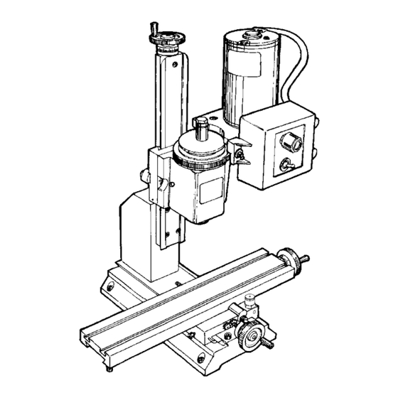
Z
FIGURE 1—The axes of movement for milling on a standard
3-axis vertical milling machine.
(NOTE: Lighter than normal cuts should be taken when the
alignment key is not in place.) The latter method must be
used for drilling on 5000/5400-series mills to keep the drill
movement parallel with the machine slide. Angle drilling
can also be accomplished without removing the alignment
key by using the optional rotary column attachment (P/N
3500). (The Model 2000 mill is also capable of angle
drilling due to its multi-axis design.) All machine slides
SHERLINE PRODUCTS INC. • 3235 Executive Ridge • Vista • California 92081-8527 • FAX: (760) 727-7857
Toll Free Order Line: (800) 541-0735 • International/Local/Tech. Assistance: (760) 727-5857 • Internet: www.sherline.com
X
Y
Vertical Milling Machine
Operating Instructions
have an adjustable gib to compensate for any "play" that
may develop. (See "adjusting gibs" on page 12 of the
Assembly and Instruction
It is assumed that anyone purchasing a vertical milling
machine has had some experience working with metal
cutting tools; therefore, these instructions are somewhat
limited for a beginner. There is enough information,
however, to enable a good craftsman to get started. Using a
vertical mill correctly takes more skill and experience than
is required for lathe operation because of the additional
axis (vertical) and the more varied type of work that can
be performed.
The machine must be well maintained, for it is subject to
higher stresses than a lathe. This particular mill is one of
the smallest being manufactured and is an extremely useful
tool. However, it would be unreasonable to clamp a 3-pound
piece of stainless steel to the work table and expect to make
a 1-pound part from it. The key point is to work within the
capabilities of the machine, and those limitations can only
be determined by the operator.
Helpful Tips for Milling
•
This is a small, light-duty mill and should not be used
to remove large amounts of stock that could be easily
removed with a hacksaw. For efficiency, select a piece
of stock as close to finished size as possible.
•
Stresses on a mill are quite high when cutting most
materials; therefore, gib and backlash adjustments must
be properly maintained.
•
End mills must run true and be sharp. Holding end
mills in a drill chuck is a poor practice. Use collets or
an end mill holder instead. The 3/8" end mill holder
(P/N 3079) allows you to use a large range of readily
available 3/8" end mills with your machine. (Several
other size inch and metric end mill holders are also
available.)
•
Fly cutting is an excellent way of removing stock from
flat surfaces.
•
Normal machine alignment is adequate for most
work, but if the work is exceptionally large or requires
extreme accuracy, shims may be employed to improve
machine alignment.
•
For accurate setups you should have and know how to
use a dial indicator.
Guide.)
4/21/16
Advertisement

Related Manuals for Sherline Products 5000 series


Summary of Contents for Sherline Products 5000 series
-
Page 1: Operating Instructions
All machine slides SHERLINE PRODUCTS INC. • 3235 Executive Ridge • Vista • California 92081-8527 • FAX: (760) 727-7857 4/21/16 Toll Free Order Line: (800) 541-0735 • International/Local/Tech. Assistance: (760) 727-5857 • Internet: www.sherline.com... - Page 2 • Often, more time will be spent making fixtures to hold work than doing the actual machining. • To help save time on many simple setups, a good mill vise is a must. A drill press vise is not designed for the P/N 3012 HOLD-DOWN forces involved in milling.
- Page 3 machining at the end of the job rather than at the beginning. • The method of holding the work is also determined by the type of machining to be performed. For instance, work that involves only small drilling jobs does not have to be held as securely as work to be milled.
- Page 4 Study the relationship of cutting edges to the material being cut as shown in Figure 4. Note that in one case the tool will tend to climb onto the work, whereas in the other case the tool will tend to move away from the cut. The result is that climb milling should normally be avoided except for very light finishing cuts.
- Page 5 FIGURE 7—Indicating in the center of a hole. FIGURE 6—Indicating in the jaws of a vise. Shown is a Starrett “Last Word” Indicator. Starrett gauges are available in numerous in the spindle and see that it runs perfectly true. Using a sizes and types.
- Page 6 of making a part to much closer tolerances than those of the machine with which he is working. The accuracy of the parts you make is limited only by your skill as a craftsman and the quality of your measurement equipment. Accuracy should be the ultimate goal of every machinist! Cutting Speeds for Milling Speed Adjustment Chart...
- Page 7 As a convenience to our customers, Sherline keeps in FIGURE 66—Mill inventory many of the popular sizes of end mills that are column saddle lock appropriate for use on our machines. See our “Cutting Tools Price List” for selection. End mills may also be purchased on-line or from your local industrial machine MILL SADDLE shop supply outlet.
- Page 8 34220 54020/54120 40580 SHERLINE PRODUCTS INC. • 3235 Executive Ridge • Vista • California 92081-8527 • FAX: (760) 727-7857 3/6/17 Toll Free Order Line: (800) 541-0735 • International/Local/Tech. Assistance: (760) 727-5857 • Internet: www.sherline.com Mill Instructions, Pg. 8 OF 10...
- Page 9 SHERLINE Lathes and Mills KEY TO MATERIALS: A=Aluminum, B=Brass, C=Composite, DC=Die Cast, P=Plastic, U=Urethane, S=Steel PART NO. DESCRIPTION MATERIAL PART NO. DESCRIPTION MATERIAL 12970 Headstock Spacer Block (Deluxe Mill) 40340 110-32 x 1” Skt. Hd. Cap Screw 30220 Toggle Switch Retaining Ring 40370 Leadscrew Support 30230...
- Page 10 PART NO. DESCRIPTION MATERIAL PART NO. DESCRIPTION MATERIAL 43140 DC Speed Control Tab, Small 50220 1/4-20 x 1-3/4” Skt. Hd. Cap Screw 43150 DC Speed Control Tab, Large 50240 Headstock Pivot Pin, Mill 43160 Belt Guard, Outer 50280 Thrust Collar, Mill 43170 6-32 x 1-3/8”...
Need help?
Do you have a question about the 5000 series and is the answer not in the manual?
Questions and answers