AMX Enova DGX 100 Series Hardware Reference Manual
Digital media switchers, enclosures, input/output/expansion boards
Hide thumbs
Also See for Enova DGX 100 Series:
- Quick start manual (2 pages) ,
- Quick start manual & warranty (2 pages)
Table of Contents
Troubleshooting

Related Manuals for AMX Enova DGX 100 Series


Summary of Contents for AMX Enova DGX 100 Series
- Page 1 HARDWARE REFERENCE MANUAL ® ENOVA D I G I T A L M E D I A S W I T C H E RS E N OVA D GX 1 0 0 S E R I E S E N C LO S U RE S E N OVA D GX I N P U T B O A RD S E N OVA D GX O U T P U T B O A RD S E N OVA D GX E X P A N S I O N B O A RD S...
- Page 2 COPYRIGHT NOTICE AMX© 2018, all rights reserved. No part of this publication may be reproduced, stored in a retrieval system, or transmitted, in any form or by any means, electronic, mechanical, photocopying, recording, or otherwise, without the prior written permission of AMX. Copyright protection claimed extends to AMX hardware and software and includes all forms and matters copyrightable material and information now allowed by statutory or judicial law or herein after granted, including without limitation, material generated from the software programs which are displayed on the screen such as icons, screen display looks, etc.
- Page 3 (recast) Directive 2012/19/EU; European Union Eco-Design Directive 2009/125/EC; European Union Registration, Evaluation, Authorization and Restriction of Chemicals (REACH) Regulation (EC) 1907/2006. You may obtain a free copy of the Declaration of Conformity by visiting http://www.amx.com/techcenter/certifications.asp. WEEE NOTICE This appliance is labeled in accordance with European Directive 2012/19/EU concerning waste of electrical and electronic equipment (WEEE).
- Page 4 Anyone performing field maintenance on AMX equipment should use an appropriate ESD field service kit complete with at least a dissipative work mat with a ground cord and a UL listed adjustable wrist strap with another ground cord.
- Page 5 CHINA MARKINGS (ONLY FOR INSTALLATIONS LOCATED IN CHINA) 该设备的设计和测试是在海拔 2000 米高度以下进行的 , 它只适用在海拔 2000 米以下的地区 . 在海拔 2000 米以上使用可能会导致潜 在的安全隐患 . This symbol denotes that the device is not to be used at altitudes exceeding 2000 meters. 该设备的设计和测试是在非热带气候条件进行的 , 它只适用在非热带气候的地区 . 在热带气候地区使用可能会导致潜在的安全隐患 . This symbol denotes that the device is only to be used in climate regions that are not-tropical.
-
Page 6: Table Of Contents
AMX Control Devices ............................. 31 BCS (Basic Control Structure) Protocol ......................31 Third-Party Controllers ............................31 Enova DGX 100 Series and Enova DGX 8/16/32/64: Differences ........... 32 System Diagnostic Options ......................33 System Configuration Interface - Status Page ..................33 DGX_SHELL Commands ........................ - Page 7 DGX 800 ..........................35 Front Panel........................... 35 Power Indicator LED Behavior ......................35 Rear Panel............................ 35 Power Supplies (x2) ..........................35 Specifications ..........................36 DGX 1600 ..........................37 Front Panel........................... 37 Power Indicator LED Behavior ......................37 Rear Panel............................ 37 Power Supplies (x2) ..........................37 Specifications ..........................
- Page 8 Rack-Mounting Enova DGX 100 Series Enclosures ............... 48 Rack-Mounting DGX 6400 Enclosures ....................48 Rack-Mounting DGX 800/1600/3200 Enclosures ................... 49 Installing Boards, Connecting Devices and Powering up the DGX Enclosure ........49 Special Information for Audio Expansion Boards .................. 49 Installation Options..............................
- Page 9 Enova DGX Switcher Hardware Troubleshooting ....................61 Video and Audio Troubleshooting........................62 AMX Software Troubleshooting..........................62 Contacting Technical Support........................ 62 AMX Contact Information ............................62 Applying Power and Startup ....................63 Overview............................63 Power Budget Planning for Systems with DXLink Twisted Pair Boards ........63 Complete Power Redundancy Setup.....................
- Page 10 Muting and Unmuting Outputs ....................... 75 Unmuting an Output While In Mute Mode ....................76 Adjusting Input Gain ..........................76 Setup Options ..........................76 Software Version........................... 77 Checking Software Version Information....................77 Master Info ............................77 Checking Integrated Master Info ......................77 Default Virtual Matrix..........................
- Page 11 Overview............................. 112 Signal Routing ..........................112 HDCP Compliance..........................112 InstaGate Pro Technology ........................113 DXLink - Twisted Pair Boards Specifications................113 Compatible AMX DXLink - Twisted Pair Transmitters and Receiver ............ 113 Enova Digital Media Switchers - Hardware Reference Manual...
- Page 12 Compatible AMX Solecis Digital Switchers (1 Output per Switcher) ............. 113 EDID Resolutions Supported through Local DDC ................ 114 Standard Timings (Default Shipping EDID) ................... 114 Established Timings ..........................115 CTA Video Information Code (VIC) Formats ..................115 Audio Data Block..............................115 System Setup with DXLink Transmitters and Receivers.............
- Page 13 Options for DXLink System Setup......................127 Example of Typical Setup with DXLink Twisted Pair 4K Transmitter and Receiver ......127 Functions of DXLink Transmitters and Receivers ................128 Important Power Considerations for Enova DGX 3200 Endpoint Systems ..........128 Power Budget Planning for Enova DGX 3200 with DXLink Boards ..........129 Power Budget Calculation ........................
- Page 14 OSHA Directive ............................. 140 Wiring for Directional Modes ....................... 140 Fiber Optic Cable Wiring for Bidirectional Mode – Duplex Only (Default)............140 Fiber Optic Cable Wiring for Unidirectional Mode – Simplex (Default) or Duplex (Configurable)....141 Fiber Optic Cable Wiring for Data Link-lost Mode – Duplex Only ..............141 Fiber Optic Transceivers ........................
- Page 15 Enova DGX Model Specific Dante Audio Switching Board Location ............151 Dante Audio Switching Boards Specifications................152 System Examples ........................153 Daisy Chain Topology (Default)......................153 Star Topology without Redundancy ...................... 155 Star Topology with Redundancy ......................155 Dante Audio Switching Board Numbering Overlays..............156 Applying Dante ASB Overlays to Numbering Plates ................
- Page 16 Audio Switching Board Connectors ...................... 169 Attaching Terminal Block Audio Connectors ..................169 Important to Know When Wiring Audio Switching Board Terminal Block Connectors ........ 169 Wiring Audio Connectors........................169 Options for Wiring ASB Boards to Source and Destination Devices.............. 170 Attaching the HSSI SMA (Sub-miniature version A) Cable..............
- Page 17 Accessing the System Configuration Interface ................184 Username and Password........................184 System Configuration Interface Tips ..................184 Menu Bar ............................ 185 Home Page ..........................185 Switching Page ........................... 185 Switching Page Components ........................ 185 Color-Coded Switch Selection and Switching Orientation ..............186 Legend Page .................................
- Page 18 Confirming Board Versions ......................203 Confirm Board Versions ........................203 Sending a Firmware .kit File to the Enclosure................203 Enabling Control Characters in a Terminal or Telnet Session............ 203 NetLinx Studio Tips........................203 Integrated Master - NetLinx Programming .................204 Overview............................. 204 Device Numbering ..........................
- Page 19 ?AUDOUT_NAME ................................... 216 AUDOUT_NAME..................................216 ?VIDIN_PREF_EDID ................................216 VIDIN_PREF_EDID ................................216 ?VIDIN_RES_REF .................................. 216 ?VIDIN_STATUS ..................................216 ?VIDOUT_ASPECT_RATIO ..............................217 VIDOUT_ASPECT_RATIO ............................... 217 ?VIDOUT_BLANK................................... 217 VIDOUT_BLANK ..................................217 VIDOUT_BLOCKED ................................217 ?VIDOUT_BRIGHTNESS ................................. 217 VIDOUT_BRIGHTNESS................................217 ?VIDOUT_CABLE_CONNECTED ............................. 217 ?VIDOUT_CONTRAST ................................218 VIDOUT_CONTRAST ................................
- Page 20 AUDIN_COMPRESSION_ATTACK ............................225 ?AUDIN_COMPRESSION_RATIO............................225 AUDIN_COMPRESSION_RATIO.............................. 225 ?AUDIN_COMPRESSION_RELEASE............................226 AUDIN_COMPRESSION_RELEASE ............................226 ?AUDIN_COMPRESSION_THRESH ............................226 AUDIN_COMPRESSION_THRESH ............................226 ?AUDIN_GAIN..................................226 AUDIN_GAIN ..................................226 ?AUDIN_STEREO................................... 226 AUDIN_STEREO..................................226 Audio Output SEND_COMMANDs ....................... 227 ?AUDOUT_EQ_CF.................................. 227 AUDOUT_EQ_CF..................................227 ?AUDOUT_EQ_ENABLE................................. 227 ?AUDOUT_BALANCE ................................227 AUDOUT_BALANCE................................
- Page 21 Preparation Checklist: ......................... 234 Sending Firmware (*.KIT) Files to the Enova DGX ..............234 Master Upgrade ..............................236 Enova DGX 100 Series Upgrade (Offline Upgrade) ................... 236 Changing the Proxy Setting ......................237 Adding an Exception to the Proxy Settings ................... 237 Checking Cache Settings in a Web Browser................
- Page 22 To reset factory settings and enable the most recent EDIDs on a DXLink Fiber TX via Pushbutton ID: ..266 Downgrade Sequence Overview ....................266 Downgrading DXLink Endpoint Firmware .................... 267 Downgrading Enova DGX 100 Series Enclosures.................. 267 Downgrading the Front Control Panel....................267 Removing 100 Series CPU Board and Installing Enova DGX 8/16/32/64 CPU Board......267 Important Information for CPU Downgrade from 100 Series to 8/16/32/64.............
- Page 23 Software Installation on PC and Enova DGX Connection............. 270 To install DGX Configuration Software: ....................270 DGX Configuration Software Setup....................... 270 General Notes for Working with DGX Configuration Software ............. 271 Scaler Mode View ........................272 Scaler Modes............................272 Auto Mode................................272 Bypass Mode ................................
- Page 24 External Serial Control via USB Control Port ................283 Attaching a PC To the USB (mini-B) Port and Establishing a Virtual COM Port........283 External Serial Control via DB-9 Control Port................286 PC Requirements for Serial Control..................... 286 RS-232 Pin Diagram ..........................286 Establishing External Serial Control Via the Control (DB-9 serial) Port ..........
-
Page 25: Enova Dgx 100 Series - Overview
112. For system setup information, see page 116. IMPORTANT: Before connecting a Solecis Digital Switcher to a DXLink Twisted Pair Input Board in an Enova DGX 100 Series Digital Media Switcher, both the Solecis unit and all DXLink Twisted Pair boards must be upgraded with the latest available firmware versions. -
Page 26: Enova Dgx Dxlink Twisted Pair 4K Boards
NOTE: Enova DXLink Twisted Pair 4K Boards must be used in conjunction with DXLink Twisted Pair 4K Transmitters and Receivers or other AMX DXLink signal management solutions. For model numbers of compatible Transmitters and Receivers, see page 123. For system setup information, see page 127. -
Page 27: Connectors And Signal Types
Enova DGX 100 Series - Overview Input and output channel numbers correspond to the connectors and are located as follows: Enova DGX 800/1600 – on the vertical numbering plate (metal strip) between input and output connectors. Enova DGX 3200 – on the horizontal numbering plate (metal strip) directly above connectors. -
Page 28: Important Notes On Using Expansion Boards
USB Program port driver for Windows 7 and Windows 8 Telnet Commands for the Enova DGX 100 Series NetLinx NX Master Automatic Configuration of AMX Devices via ICS LAN When an ICS LAN capable endpoint device (e.g., a DXLink Twisted Pair Transmitter connected to a DXLink Twisted Pair Input Board) is initially connected, the integrated Master sends ICS LAN messages to the device and conducts automatic configuration (auto-setup), after which the device reboots. -
Page 29: Link-Local Fallback In Dhcp Mode (Ipv4 Only)
The integrated NetLinx NX Master is configurable for communication with a PC over the switcher’s USB Program port. On Enova DGX 100 Series Switchers, the USB Program port includes pre-loaded drivers for use with a PC running either Windows 7 or Windows 8. -
Page 30: Enova Dgx Netlinx And Control Specifications
Switching Configuration Information The configuration file stored on the CPU contains routing and control information for the AMX Enova Routing System. NOTE: The configuration file is automatically generated by the system based on its hardware – input and output boards, expansion boards, front control panel, CPU, etc. -
Page 31: Available Levels (Virtual Matrices)
Audio Switching Boards When Audio Switching Boards (ASB or ASB-DAN) are in the system, the Enova DGX 100 Series supports audio breakaway on VM 2 (via the Audio Switch Mode on the System Configuration interface). The system can route the embedded audio from any digital video input to any digital video output. -
Page 32: Enova Dgx 100 Series And Enova Dgx 8/16/32/64: Differences
Enova DGX 100 Series and Enova DGX 8/16/32/64: Differences The Enova DGX 100 Series has incorporated a number of technological advancements which resulted in changes that may be of interest to users of previous Enova DGX products. In order to assist these users, we have included the table below which captures some of the main system differences (highlighted cells represent changes that may affect programming code in existing systems). -
Page 33: System Diagnostic Options
Displays Integrated Master info and provides basic audio support (for embedded audio only) System Diagnostic Options The two system diagnostic options for the Enova DGX 100 Series are the Status page in the System Configuration interface and DGX_SHELL commands. System Configuration Interface - Status Page The Status page in the System Configuration interface (Switcher/Status) displays status for the power supplies, fans, CPU, I/O boards, and expansion boards (see page 141). -
Page 34: Instagate Pro Technology
Enova DGX 100 Series - Overview InstaGate Pro Technology InstaGate Pro Technology eliminates latency (time required for authentication) in the switcher for HDCP negotiations with the displays in a system. The latency is typically experienced when HDCP authenticates HDMI source and destination devices every time a new switching combination between a source device and display occurs. -
Page 35: Dgx 800
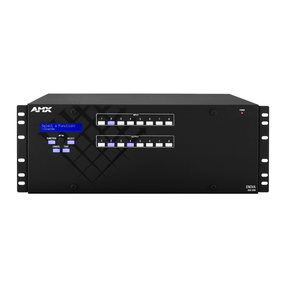
DGX 800 DGX 800 Front Panel The front panel of DGX 800 Enclosures features an LCD screen, Control Panel, Input and Output keys and Power Indicator LED (FIG. 1): Power Indicator LED Input keys Output keys Control Panel (Control keys/Dial) FIG. -
Page 36: Specifications
DGX 800 Specifications DGX 800 Specifications Parameter Value Approvals UL 60950-1, CSA 60950-1, IEC 60950-1, IEC 62368-1, CE EN 60950-1, CE EN 55022 Class A, CE EN 55024, FCC CFR Title 47 Part 15 Subpart B Class A, ICES-003 Class A, RoHS, WEEE AC Power per Supply 100-240 +/-10% VAC single phase, 50/60 Hz Power Capacity (max.) -
Page 37: Dgx 1600
DGX 1600 DGX 1600 Front Panel The front panel of DGX 1600 Enclosures features an LCD screen, Control Panel, Input and Output keys and Power Indicator LED (FIG. 4): Power Indicator LED Input keys Output keys Control Panel (Control keys/Dial) FIG. -
Page 38: Specifications
DGX 1600 Specifications DGX 1600 Specifications Parameter Value Approvals UL 60950-1, CSA 60950-1, IEC 60950-1, IEC 62368-1, CE EN 60950-1, CE EN 55022 Class A, CE EN 55024, FCC CFR Title 47 Part 15 Subpart B Class A, ICES-003 Class A, RoHS, WEEE AC Power per Supply 100-240 +/-10% VAC single phase, 50/60 Hz Power Capacity (max.) -
Page 39: Dgx 3200
DGX 3200 DGX 3200 Front Panel The front panel of DGX 3200 Enclosures features an LCD screen, Control Panel, Input and Output keys and Power Indicator LED (FIG. 7): Power Indicator LED Input keys Output keys Control Panel (Control keys/Dial) FIG. -
Page 40: Specifications
DGX 3200 NOTE: For information on applying power, see page 63. Specifications DGX 3200 Specifications Parameter Value Approvals UL 60950-1, CSA 60950-1, IEC 60950-1, IEC 62368-1, CE EN 60950-1, CE EN 55022 Class A, CE EN 55024, FCC CFR Title 47 Part 15 Subpart B Class A, ICES-003 Class A, RoHS, WEEE AC Power per Supply 100-240 +/-10% VAC single phase, 50/60 Hz... -
Page 41: Dgx 6400
DGX 6400 DGX 6400 Front Panel The front panel of DGX 6400 Enclosures features an LCD screen, Control Panel, Input and Output keys and Power Indicator LED (FIG. 10): Power Indicator LED Input keys Control Panel (Control keys/Dial) Output keys FIG. -
Page 42: Rear Panel
DGX 6400 Rear Panel Enova DGX 6400 enclosures have 32 horizontal I/O board slots (16 slots each for input and output boards with four connectors each), allowing for a maximum configuration of 64x64. FIG. 11 shows the rear panel of an DGX 6400 enclosure, fully loaded for 64x64 switching.: Numbering plate Expansion slot... -
Page 43: Specifications
DGX 6400 Specifications DGX 6400 Specifications Parameter Value Approvals UL 60950-1, CSA 60950-1, IEC 60950-1, IEC 62368-1, CE EN 60950-1, CE EN 55022 Class A, CE EN 55024, FCC CFR Title 47 Part 15 Subpart B Class A, ICES-003 Class A, RoHS, WEEE AC Power per Supply 100-240 +/-10% VAC single phase, 50/60 Hz Power Capacity (max.) -
Page 44: Installation And Setup
Installation and Setup Installation and Setup DGX Enclosure MAC Address / Serial Number MAC Address Serial Number FIG. 13 DGX Enclosures rear view (CPU/Control board) - MAC Address and Serial Number decals The MAC address for the system is located directly above the Control (DB-9 serial) port on the CPU. ... -
Page 45: Mechanical (Rack) Loading
Installation and Setup CAUTION: To prevent overheating, avoid placing high heat producing equipment directly above or below the enclosure. The system requires a minimum of one empty rack unit above and below (three empty rack units are recommended). Verify that the openings on the top and sides of the enclosure are not blocked and do not have restricted air flow. Mechanical (Rack) Loading When installing equipment in a rack, distribute the weight to avoid uneven mechanical loading. -
Page 46: Options For System Setup With Dxlink Twisted Pair 4K
Installation and Setup IMPORTANT: Before connecting a Solecis Digital Switcher to a DXLink Twisted Pair Input Board in an Enova DGX 100 Series Digital Media Switcher, both the Solecis unit and all DXLink Twisted Pair boards must be upgraded with the latest available firmware versions. -
Page 47: Rack Installation And System Setup
Installation and Setup Rack Installation and System Setup Enova DGX 100 Series Switchers can be mounted in a standard EIA 19 in. (48.26 cm) rack. Required Items Enclosure Enova DGX 6400 only – two rack mounting handles (provided) ... -
Page 48: Rack-Mounting Enova Dgx 100 Series Enclosures
Installation and Setup Rack-Mounting Enova DGX 100 Series Enclosures Rack-Mounting DGX 6400 Enclosures The DGX 6400 Enclosure come with CAUTION: The Enova DGX 6400 weighs approximately 150 lb (68 kg) for a fully loaded enclosure. Installation of the DGX 6400 requires a minimum of two people, we recommend using three people for lifting and ... -
Page 49: Rack-Mounting Dgx 800/1600/3200 Enclosures
Installation and Setup Rack-Mounting DGX 800/1600/3200 Enclosures CAUTION: Installation of DGX 800/1600/3200 Enclosures requires a minimum of two people; we recommend using three people. Select a position in the rack for the enclosure that is accessible and does not restrict airflow. Position the enclosure in the rack, and install the rack ear screws on each side (FIG. -
Page 50: Installation Options
Installation and Setup Installation Options Additional installation tasks may include the following: Attaching an AxLink Device – page 59 Using the ID Pushbutton – page 60 Setting PRD Mode – page 61 Establishing Telnet connection with the CPU – page 256 ... -
Page 51: Attaching Video Input And Output Cables
Installation and Setup Attaching Video Input and Output Cables Input and output connectors are the attachment points for source and destination devices that connect to the system. Enova DGX 800 Viewed from the rear of the enclosure, the Enova DGX 800/1600 input boards (for attaching sources) are on the left, and the output boards (for attaching destinations) are on the right. -
Page 52: Wiring Audio Inputs And Outputs
System Setup for Using the Integrated NetLinx NX Master The Enova DGX 100 Series Switcher has an integrated NetLinx NX Central Control Processor (Master) that establishes its public LAN (Local Area Network) connection through the LAN 100/1000 port on the CPU. The Master provides a System Configuration interface that allows you to make various configuration settings via a web browser on any PC connected to the public LAN. -
Page 53: Rj-45 Ports
Installation and Setup RJ-45 Ports The Enova Series CPU has two RJ-45 ports: the ICS LAN port on the left and the LAN 100/1000 port on the right. The ICS LAN port acts as a DHCP server (private LAN) and the LAN 100/1000 port acts as a DHCP client (public LAN) with each port on a separate network. -
Page 54: T568B
The port is used for peer-to-peer protocol for both Master-to-Master and Master-to-device 1319 (UDP/TCP) communications. This type of communication is used by various AMX products for communication among themselves (see page 204). Note: The integrated Master can only be configured to use Port 1319, and the ICSP cannot be disabled. -
Page 55: Avoiding Network (Ethernet) Loops
Installation and Setup Avoiding Network (Ethernet) Loops Only one connection to the Public LAN is permitted within a switching system with DXLink support. NOTE: This applies to systems with DXLink Twisted Pair and/or DXLink Fiber Boards. Network loops must be avoided. A network loop is created when the enclosure and one or more DXLink Modules or Wallplates within the system are connected to the same Public LAN as the Enova DGX. -
Page 56: Connecting An Enova Dgx To A Public Lan Via The Lan 100/1000 Port
To prevent the possibility of the IP address changing at power up, you can change the DHCP address to a static IP address (see the NetLinx NX Central Controllers WebConsole & Programming Guide at www.amx.com). The integrated Master’s IP address is available via the control panel at Setup Options/Master Info/IP Address. -
Page 57: System Configuration Interface Setup
HTML5 features NOTE: User experience may differ due to browser support for HTML5. Setting up the system to use AMX’s System Configuration interface requires completing the following three items. Detailed instructions for each item are given. -
Page 58: Audio Control And Signal Processing Options
BCS Commands Volume, input gain, and mute – See the BCS (Basic Control Structure) Protocol Programming Guide at www.amx.com. Establishing Serial Communication with a PC via the Program Port Program Port The Enova DGX Switcher’s integrated NetLinx NX Master is equipped with a low-speed USB connection labeled "Program."... -
Page 59: Attaching An Axlink Device
For NetLinx programming purposes, each AxLink device must be assigned a unique number to locate that device on the bus. The range for AxLink device numbers is 1-255. AMX best practices requires assigning device numbers in three groups: Axcess Control Cards: 1 - 95 ... -
Page 60: Setting An Axlink Device Address
On the bottom/side of the AxLink device, set the device’s DIP switch toggles to an appropriate device number according to AMX best practices (see established ranges above). Connect AxLink cables from the AxLink device to the AxLink port on the Enova DGX CPU. -
Page 61: Restoring The Factory Firmware Image And Factory Default Settings
Installation and Setup Restoring the Factory Firmware Image and Factory Default Settings Verify that the Master is currently booting. NOTE: The Master is booting when the Program port Status and Input LEDs are ON (green and yellow respectively) and the Output LED (red) is OFF. Press and hold the ID Pushbutton for 20 seconds or longer. -
Page 62: Video And Audio Troubleshooting
If this manual has not satisfactorily answered your questions regarding the Enova DGX Switcher or the system is not operating as expected, please contact your AMX representative or technical support. Have the serial numbers for your system and any applicable AMX accessory devices ready (the numbers are normally located on the rear of the enclosure or accessory devices). -
Page 63: Applying Power And Startup
Applying Power and Startup Applying Power and Startup Overview The enclosure’s universal power receptacles will accept all major international standard power sources. Two US power cords are included with all enclosures shipped within the US. Maximum power specifications are on each power receptacle (and are also listed on page 20). -
Page 64: Applying Power
Applying Power and Startup Applying Power Attach the first two source and destination devices (attach the remaining devices in Step 9 after executing the test switch in Step 8). Do not apply power to the source and destination devices until Step 7. If connecting devices to DXLink Twisted Pair Boards, the boards require DXLink Transmitters and Receivers. -
Page 65: Redundant Power Supply (Rps)
Applying Power and Startup Redundant Power Supply (RPS) Every Enova DGX 800/1600/3200 enclosure ships with two mutually-redundant (hot-swappable) power supplies; every Enova DGX 6400 enclosure ships with four. Enova DGX 800/1600/3200 – Power indicator on the front of the enclosure illuminates constant red if a problem ... -
Page 66: Cpu/Control Board (All Dgx 100 Series Enclosures)
For selecting static IP or DHCP, resetting the factory defaults, and restoring the factory firmware image (see page 60). AxLink port/Status LED 4-pin captive wire connector for supporting AMX AxLink devices. The LED to the right of the AxLink port indicates AxLink data activity (see page 59). Config DIP switch 2-position toggles for setting the Program Run Disable (PRD) mode (see page 61). -
Page 67: Control Panel
The Control Panel on the front of all Enova DGX enclosures) is used to control system switches and system attributes. All Enova DGX 100 Series Switcher Control Panels function the same, but have input and output key support respective to their size. -
Page 68: Input And Output Keys
Control Panel Input and Output Keys Input and Output keys correspond to the input and output connections on the rear of the enclosure (FIG. 35). These keys are used to select the inputs and outputs for routing source signals to destination devices, as well as for status and audio operations. -
Page 69: Enova Dgx Control Panel - Basic Tasks
Labeling Input and Output Keys Each Enova DGX Switcher ships with a kit for custom labeling. To order additional kits, contact your AMX representative. The Control Panel Label Kit (KA1056-01) includes: Perforated card stock sheets – Print, separate labels, and slide into holders. -
Page 70: Executing Switches
Control Panel Type the labels in the preformatted cells on the template according to the instructions in the template (if desired, use standard Excel editing tools to alter font size, spacing, color, etc.). Do not modify the cell size. Save the file for future use (recommended). Print the labels on the perforated sheets provided, using any standard laser printer. -
Page 71: Changing The Virtual Matrix
Control Panel Complete audio switching functionality is available via the System Configuration interface (see page 184) or via SEND_COMMANDs (see page 225). Changing the Virtual Matrix Enova DGX Switchers support three virtual matrices for switching signals: VM 0 Default (Audio follow Video) ... -
Page 72: Verifying Signal Status
A system state can be restored at any time by selecting the assigned global preset number. Depending on whether or not the system includes Audio Switching Boards, global presets operate in one of two ways in Enova DGX 100 Series Switchers: Enova Digital Media Switchers - Hardware Reference Manual... -
Page 73: Systems Without Audio Switching Boards (Asb Or Asb-Dan)
Control Panel Systems without Audio Switching Boards (ASB or ASB-DAN) A global preset number can be assigned to a routing state during runtime and stored by the system, allowing you to replicate an entire system’s routing state. NOTE: The global preset will not affect the injection/extraction setting on any channel of any AIE Board. Systems with Audio Switching Boards (ASB or ASB-DAN) A global preset number can be assigned to a routing state during runtime and stored by the system, allowing you to replicate a subset of the system state. -
Page 74: Locking And Unlocking
Control Panel Global Preset 3 is executed. The system now reflects the routing state that it was in when Global Preset 3 was defined. The system returns to the Global Preset sub-menu. Press the Function key to return to the Function menu. NOTE: Status is not invalidated by global presets. -
Page 75: Audio Adjustments On The Control Panel
Control Panel When the panel is placed in any of the Audio Modes, available keys will be blue and any unavailable ones will not be illuminated. When you select a blue key, it turns white indicating that it is ready for the audio adjustment. Audio Adjustments on the Control Panel May be made at any time during normal operation ... -
Page 76: Unmuting An Output While In Mute Mode
Control Panel Press the Select key. The system is in Mute Mode (all Input keys are turned off, and the available Output keys turn blue), and any muted Output keys turn white. Current Routing Level Press the Output key that corresponds to the output to be muted. The output is muted, and the Output key turns white. -
Page 77: Software Version
Control Panel Software Version The Software Version Screen provides the following information: Driver – Control Panel’s firmware version Built – date the Control Panel’s software was built Host – software version of the initial operating system (IOS) for the Control Panel ... -
Page 78: Default Virtual Matrix
Control Panel Press the Select key again to choose Master Info. The Master Info Screen appears. Press the Select key again to choose System Number. - or - Scroll with the Control Dial to choose other Master Info information. Press the Cancel key to return to the Setup Options sub-menu. - or - Press the Function key to return to the Function menu. -
Page 79: Setting The Password
Control Panel Setting the Password The Enova DGX Control Panel’s default password is "1 2 3 4 5" entered using the first five input keys. A new password can be set using any combination of five of the Input keys 1 through 8 when the LCD displays "Enter New PWD" (Step 5 in the following procedure). -
Page 80: Enabling Error Code Reporting
Control Panel For the following instructions, establish serial control and open a terminal emulation program, e.g., the terminal in NetLinx Studio (Tools/Terminal Session). Enabling Error Code Reporting Enter $ERR=1! The system responds with a V. NOTE: If the power is cycled after this procedure, you will need to enable error code reporting again. Turning Error Code Reporting Off Enter $ERR=0! Most Common System Error Code... -
Page 81: 4K60 Hdmi Input & Output Boards
4K60 HDMI Input & Output Boards 4K60 HDMI Input & Output Boards Overview This chapter pertains to Enova DGX 4K60 HDMI Input and Output Boards: 4k60 HDMI Input Board (FG1061-542) 4k60 HDMI Output Board (FG1061-552) Enova DGX 4K60 HDMI Boards indicate "4K60"... -
Page 82: 4K60 Signal Routing
4K60 HDMI Input & Output Boards 4K60 Signal Routing DGX 4K60 HDMI Input Boards route video from a source device through the Enova DGX to an output board (or via a DXLink Output Board to a DXLink Receiver). However, 4K60, 4K30, and 2K signals require substantially different hardware support. -
Page 83: Enova Dgx 4K60 4:4:4 Hdmi Input Board - Specifications
Video Pixel Clock (Max) When used with compatible Enova DGX 100 series enclosures*: Up to 600 MHz Progressive Resolution Support When used with compatible Enova DGX 100 series enclosures*: 480p up to 4096x2160 @ 60Hz, 4:4:4 Interlaced Resolution Support 480i, 576i, 1080i NOTE: If input is interlaced, all scaled outputs will de-interlace video to a progressive resolution format. -
Page 84: Enova Dgx 4K60 4:4:4 Hdmi Output Board - Specifications
Please see Input Board EDID details in the EDID Resolutions section on page 85. EDID * Compatible Enova DGX 100 Series Enclosures are those Enova DGX 800, 1600, 3200 or 6400 enclosures built on or after June 1, 2016 Enova DGX 4K60 4:4:4 HDMI Output Board - Specifications... -
Page 85: 4K60 Hdmi Board Default Edid Resolutions Supported Through Local Ddc
Audio lags video by 33ms default – Adjustable down to 1 ms lag (Switched Audio Mode) * Compatible Enova DGX 100 Series Enclosures are those Enova DGX 800, 1600, 3200 or 6400 enclosures built on or after June 1, 2016 4K60 HDMI Board Default EDID Resolutions Supported through Local DDC The following tables provide the default EDID for 4K60 HDMI Boards, which is the same as the default for 4K30 boards. -
Page 86: Audio Data Block
4K60 HDMI Input & Output Boards SVD # Resolution Refresh Rate and Aspect Ratio VIC # CTA VIC HDMI VIC 720x576p 50 Hz 16:9 VIC = 18 720(1440)x576i 50 Hz 4:3 VIC = 21 720(1440)x576i 50 Hz 16:9 VIC = 22 1920x1080i 50 Hz 16:9 VIC = 39... -
Page 87: 4K Hdmi Standard Timings
4K60 HDMI Input & Output Boards Resolution Refresh Rate and Aspect Ratio CTA VIC 1920 x 1080i 50 Hz 16:9 2560 x 1080 59.94/60 Hz 64:27 2560 x 1080 50 Hz 64:27 640 x 480 59.94/60 Hz 4:3 4K HDMI Standard Timings Resolution Refresh Rate 1920x1200... -
Page 88: Attaching Hdmi Connectors
4K60 HDMI Input & Output Boards Attaching HDMI Connectors The HDMI connector has a center screw for locking capability. Refer to the specifications tables (page 83, page 84) for detailed cable requirements. Use a "Premium High Speed Certified" HDMI cable for any 4K50/4K60 format. ... -
Page 89: Video Troubleshooting
Solution No Video: incompatible format If the system has determined that the full path is UNSUPPORTED for the active video format and the downstream AMX equipment, it is often reported via the sink OSD as "Incompatible Format".t The System Configuration Interface displays an amber bar on Either provide equipment that supports the desired format, or limit the the channel tile (only when there is a sink plugged in.) - Page 90 4K60 HDMI Input & Output Boards Video Troubleshooting (Cont.) Problem Solution Execute a AV channel reset on the input using the MCPU console command "reboot -u 6 BCPUx:y" if the content is HDCP and the input channel reset does not resolve, then disconnect each output allowing 5 seconds between disconnects.
-
Page 91: Audio Troubleshooting
4K60 HDMI Input & Output Boards Audio Troubleshooting Before troubleshooting audio, it helps to understand how the system handles EDID information: The source reads and adapts to the pre-loaded EDID on the DGX HDMI input connector. The factory default EDID is set to support 2 channel L- PCM audio. - Page 92 4K60 HDMI Input & Output Boards Audio Troubleshooting (Cont.) Problem System Type Solution 1. Verify the transmitter audio setting by using NetLinx Studio to send the following commands: ?AUDOUT_ASSIGN 2. If the port number is not the one you expect, and: a.
- Page 93 4K60 HDMI Input & Output Boards Audio Troubleshooting (Cont.) Problem System Type Solution m. OUTPUT SIDE ISSUE - Audio is not present on 2-channel sink (TV/monitor) 1. It is recommended that you set up all 2-channel-PCM-only with good video while it is present on a sinks to use switched audio.
-
Page 94: Determining The Dxlink Transmitter Source Audio Port
4K60 HDMI Input & Output Boards Determining the DxLink Transmitter Source Audio Port Active Video ?AUDIN_FORMAT_AUTO Source Audio Port HDMI ENABLED HDMI VGA/Analog ENABLED Whichever port is set in ?AUDIN_FORMAT HDMI DISABLED Whichever port is set in ?AUDIN_FORMAT VGA/Analog DISABLED Whichever port is set in ?AUDIN_FORMAT Audio Format Support on Enova DGX Boards The following table indicates which audio formats are supported by specific Enova DGX boards. -
Page 95: Hdmi Input & Output Boards
HDMI Input & Output Boards HDMI Input & Output Boards Overview This chapter pertains to Enova DGX HDMI Input Boards and HDMI Output Boards: FG1058-540 Input board FG1061-540 4K HDMI Input Board FG1058-550 Output board Enova DGX 4K HDMI Boards indicate "4K"... -
Page 96: Instagate Pro And Smartscale
Video Pixel Clock (Max) When used with compatible Enova DGX 100 series enclosures*: Up to 600 MHz Progressive Resolution Support When used with compatible Enova DGX 100 series enclosures*: 480p up to 4096x2160 @ 60Hz, 4:4:4 Interlaced Resolution Support 480i, 576i, 1080i NOTE: If input is interlaced, all scaled outputs will de-interlace video to a progressive resolution format. - Page 97 • Yes, including HDCP 1.x and HDCP 2.x for full matrix HDCP support (includes any input to any or all outputs) • HDCP 2.2 support required by input/output board for passage of HDCP 2.2 premium content • Key Management System • AMX HDCP InstaGate Pro™ Technology • Key support up to 31devices per output CEC Support None...
- Page 98 Basic Audio: 2 Channel L-PCM 32, 44.1, 48 kHz Sampling Frequency at 16, 20 or 24 bits per sample. *Compatible Enova DGX 100 Series Enclosures are those Enova DGX 800, 1600, 3200 or 6400 enclosures built on or after June 1, 2016.
-
Page 99: Enova Dgx Hdmi Output Board - Specifications
Audio Switching Board Support Supports break-away audio switching of 2 CH L-PCM for all channels * Compatible Enova DGX 100 Series Enclosures are those Enova DGX 800, 1600, 3200 or 6400 enclosures built on or after June 1, 2016 Enova Digital Media Switchers - Hardware Reference Manual... -
Page 100: Hdmi Board Edid Resolutions Supported Via Local Ddc
HDMI Input & Output Boards HDMI Board EDID Resolutions Supported via Local DDC Standard and established timings are given in the tables following along with detailed timing blocks. NOTE: This section covers all of the default EDIDs for HDMI Input and Output Boards (not 4K HDMI Boards). In the System Configuration interface, the EDIDs contained in this section's tables are displayed in a single dropdown menu (General section, Preferred EDID menu) and VICs are differentiated by the presence of a "p"... -
Page 101: Hdmi Cta Video Information Code (Vic) Formats
HDMI Input & Output Boards HDMI CTA Video Information Code (VIC) Formats NOTE: CTA VIC formats for 4K HDMI Boards are on page 102. VIC # Resolution Refresh Rate and Aspect Ratio VIC = 1 640x480p 59.94/60 Hz 4:3 VIC = 2 720x480p 59.94/60 Hz 4:3 VIC = 3... -
Page 102: 4K Hdmi Standard Timings
HDMI Input & Output Boards 4K HDMI Standard Timings Resolution Refresh Rate Max. 1920x1200 60 Hz 1680x1050 60 Hz 1600x1200 60 Hz 1440x900 60 Hz 1360x765 60 Hz 1280x1024 60 Hz 1280x800 60 Hz 1280x720 60 Hz 4K HDMI Established Timings Resolution Refresh Rate Max. -
Page 103: Attaching Hdmi Connectors
Switcher only sees the input of that InstaGate Pro device as the one sink that it needs to verify. So even though the number of sinks each HDMI output on the switcher can handle is finite, the number of sinks can be unlimited if using AMX devices that support InstaGate Pro Technology. Steps in the Content Protection Process... -
Page 104: Supported Number Of Sinks
HDMI Input & Output Boards The Enova DGX Switcher verifies that the display devices are authorized to receive the protected content (this is the part of the process in which renewability of the SRM (System Renewability Message) list is verified; this verification of the display devices occurs inside the switcher). -
Page 105: Audio Troubleshooting
EDID, the audio may not pass interface’s Save EDID function and then paste the data from the .edid through the Enova DGX 100 Series Switcher at all or it may be file into an EDID reader program (e.g., www.edidreader.com). -
Page 106: Dvi Input & Output Boards
DVI Input & Output Boards DVI Input & Output Boards Overview This chapter pertains to the following DVI Input Board and Output Board for the Enova DGX Switcher: FG1058-600 Input board FG1058-610 Output board FIG. 40 Enova DGX DVI Input and DVI Output Boards Enova DGX Enclosure Support for DVI Input &... -
Page 107: Audio Support On Dvi Boards
DVI Input & Output Boards DVI Boards are HDCP 1.4 compatible and feature InstaGate Pro Technology for low-latency switching of HDCP protected content and support computer video up to 1920x1200 and HDTV up to 1080p. The EDID of the input will need to be changed to allow for HDMI formatted signals, so that the source device can send out that signal style. -
Page 108: Edid Resolutions Supported Through Local Ddc
HDCP Support • Full matrix HDCP support (includes any input to any or all outputs) • key Management System • AMX HDCP InstaGate Pro® Technology • key support up to 16 devices per output, independent of source device CEC Support... -
Page 109: Cta Video Information Code (Vic) Formats
DVI Input & Output Boards CTA Video Information Code (VIC) Formats VIC # Resolution Refresh Rate and Aspect Ratio VIC = 1 640x480p 59.94/60 Hz 4:3 VIC = 2 720x480p 59.94/60 Hz 4:3 VIC = 3 720x480p 59.94/60 Hz 16:9 VIC = 4 1280x720p 59.94/60 Hz 16:9... -
Page 110: Dvi Pinout
DVI Input & Output Boards DVI Pinout Pinout information for the DVI-I connector on the DVI Input and Output Boards is listed in the table below: DVI-I Pinout 1. Data 2- 9. Data 1- 17. Data 0- C1. No connect 2. -
Page 111: Troubleshooting Audio
L-PCM audio. If a sources chooses to ignore this EDID and send a format that is not in the EDID, the audio may not pass through the Enova DGX 100 Series Switcher at all or it may be Checking for Support: One way to check if a destination supports a distorted. -
Page 112: Dxlink Twisted Pair Input And Output Boards
IMPORTANT: DXLink™ Twisted Pair Boards must be used in conjunction with DXLink™ Twisted Pair Transmitters and Receivers or other AMX DXLink™ signal management solutions. NOTE: Compatibility is available between DXLink Twisted Pair equipment and DXLink Twisted Pair 4K equipment (see the "DXLink Compatibility"... -
Page 113: Instagate Pro Technology
DXLink Twisted Pair Input and Output Boards - Specifications Compatible DXLink Products Multi-Format TX, Multi-Format Wallplate TX, Decor Wallplate TX, and DXLink RX; and other AMX DXLink signal management products Compatible Formats HDMI video, audio, Ethernet, USB (HID), power, and control... -
Page 114: Edid Resolutions Supported Through Local Ddc
Shielded Cat6, Cat6A, Cat7 Note: For more details and helpful cabling information, reference the white paper titled "Cabling for Success with DXLink" available at www.amx.com or contact your AMX representative. Twisted Pair Cable Length Up to 328 ft. (100 m) Note: For more details and helpful cabling information, reference the white paper titled "Cabling for... -
Page 115: Established Timings
DXLink Twisted Pair Input and Output Boards Established Timings Resolution Refresh Rate Max. 1280x1024 75 Hz 1152x870 75 Hz 1024x768 60 Hz, 70 Hz, 75 Hz, 87 Hz 832x624 75 Hz 800x600 56 Hz, 60 Hz, 72 Hz, 75 Hz 720x400 70 Hz, 88 Hz 640x480... -
Page 116: System Setup With Dxlink Transmitters And Receivers
Enova DGX DXLink Twisted Pair Input Board for hub-style or campus-wide distribution. IMPORTANT: Before connecting a Solecis Digital Switcher to a DXLink Twisted Pair Input Board in an Enova DGX 100 Series Digital Media Switcher, both the Solecis unit and all DXLink Twisted Pair boards must be upgraded with the latest available firmware versions. -
Page 117: Functions Of Dxlink Transmitters And Receivers
DXLink Twisted Pair Input and Output Boards The Transmitter receives an HDMI signal and an audio signal from a source device. The audio can be either digital audio embedded with the HDMI signal, digital audio over S/PDIF, or analog stereo audio. Both the video and embedded audio are transmitted over twisted pair cable to the RJ-45 connector on the DXLink Input Board. -
Page 118: Important Power Considerations For Enova Dgx 3200 Endpoint Systems
DXLink Transmitters and Receivers to be powered via the switcher, and the calculator shows the resulting power draw. The Enova DGX Configuration Tool is located at www.amx.com/enova. If more DXLink units are required than the switcher can support while maintaining redundancy, they must be powered using the provided desktop power supplies (which must not be altered in any way) or a DXLink power injector;... -
Page 119: Connecting Switching Systems With Dxlink Connectors
DXLink port will automatically disable all Ethernet, power, and control on that connection port so that the only things passed down the DXLink line are the video and audio signals. When connecting switching systems via DXLink ports, AMX recommends no more than 3 switcher throughputs. ... -
Page 120: Dxlink Connector Leds
The DIP switches are on the bottom of the DXLink Modules, on the rear of the DXLink Wallplate, and on the front of the DXLink Decor Style Wallplate (hidden by front cover plate). A detailed description of functions for each toggle is provided in the Hardware Reference Manual – DXLink Twisted Pair Transmitters/Receiver at www.amx.com. Common Scenarios DIP Switch Toggle Settings Switcher Setup –... -
Page 121: Auto-Setup
Note: Connect the ICS LAN 10/100 port of the DXLink unit to the network device (e.g., laptop, IP controlled projector, AMX ICSLan EXB device). #1 Toggle settings do not apply to Wallplate TX & Decor Wallplate TX – leave #1 Toggle OFF. -
Page 122: Telnet Access To Dxlink Endpoints
DXLink Modules connected to both input and output boards. The switcher has an integrated NetLinx NX Central Control Processor which provides native AMX control at each remote location fed by a DXLink Transmitter or Receiver. Control is sent over twisted pair cable via the DXLink ports: FIG. -
Page 123: Dxlink Twisted Pair 4K Input And Output Boards
(computer, media player, etc) presenting a video resolution out of the Transmitter's range. To ensure the source device presents a resolution the DXLink Transmitter can support, simply use the Enova DGX 100 Series System Configuration interface to select a non-4K EDID (All, Wide, Full in non-4K range) to ensure a supported format is requested by the DXLink Transmitter. -
Page 124: Hdcp Compliance
DXLink Twisted Pair 4K Input and Output Boards - Specifications Compatible AMX DXLink™ 4K HDMI Decor Style Wallplate TX, 4K HDMI RX, other AMX DXLink signal management products Twisted Pair 4K Products Note: For additional compatibility with DXLink Twisted Pair products, see the "DXLink Twisted Pair 4K Transmitters and Receivers Hardware Reference Manual"... -
Page 125: Edid Resolutions Supported Through Local Ddc
PC. A list is available of HID devices which have been tested and found to work well with the latest firmware (see "DXLink - HID Supported Devices" on the RX’s product page at www.amx.com). DXLink Twisted Pair Power... -
Page 126: Standard Timings
DXLink Twisted Pair 4K Input and Output Boards Standard Timings Resolution Refresh Rate Max. 1920x1200 60 Hz 1680x1050 60 Hz 1600x1200 60 Hz 1440x900 60 Hz 1360x765 60 Hz 1280x1024 60 Hz 1280x800 60 Hz 1280x720 60 Hz Established Timings Resolution Refresh Rate Max. -
Page 127: Audio Data Block
System Setup with DXLink Twisted Pair 4K Transmitters and Receivers DXLink Twisted Pair 4K Input and Output Boards must be used in conjunction with AMX DXLink Twisted Pair 4K Transmitters and Receivers or other AMX DXLink 4K signal management solutions. This combination creates an end-to-end extender solution for transmission of HDMI (or DVI via adapter cable) over twisted pair cable. -
Page 128: Functions Of Dxlink Transmitters And Receivers
DXLink Twisted Pair 4K Input and Output Boards DXLink Twisted Pair 4K Input Board DXLink Twisted Pair 4K Output Board 4K HDMI Wallplate TX 4K HDMI RX Module Source Device Destination Device FIG. 48 DXLink Twisted Pair 4K Boards used in conjunction with DXLink TX and RX NOTE: For systems with special requirements –... -
Page 129: Power Budget Planning For Enova Dgx 3200 With Dxlink Boards
DXLink Transmitters and Receivers to be powered via the switcher, and the calculator shows the resulting power draw. The Enova DGX Configuration Tool is located at www.amx.com/enova. If more DXLink units are required than the switcher can support while maintaining redundancy, they must be powered using the provided desktop power supplies (which must not be altered in any way) or a DXLink power injector;... -
Page 130: Avoiding Network (Ethernet) Loops
DXLink port will automatically disable all Ethernet, power, and control on that connection port so that the only things passed down the DXLink line are the video and audio signals. When connecting switching systems via DXLink ports, AMX recommends no more than 3 switcher throughputs. For ... -
Page 131: Dxlink Connector Leds
IMPORTANT: Find the scenario in the table below that you want to use and set the DIP switches accordingly. The DIP switches are on the bottom of the DXLink Modules. A detailed description of functions for each toggle is provided in the Hardware Reference Manual – DXLink Twisted Pair 4K Transmitters and Receivers at www.amx.com. Common Scenarios DIP Switch Toggle Settings Switcher Setup –... -
Page 132: Auto-Setup
DXLink Twisted Pair 4K Receiver modules in auto-setup mode are accessible through the ICS LAN port on the Switcher’s CPU. Control is established through a Telnet session with appropriate Telnet commands for the DXLink Twisted Pair 4K Receiver (see the Hardware Reference Manual – DXLink Twisted Pair 4K Transmitters and Receivers at www.amx.com). CAUTION: The ICS LAN port acts as a DHCP server (private LAN) and the LAN 100/1000 port acts as a DHCP client (public LAN) with each port on a separate network. -
Page 133: Dxlink Twisted Pair / Dxlink Twisted Pair 4K Compatibility
(computer, media player, etc) presenting a video resolution out of the Transmitter's range. To ensure the source device presents a resolution the DXLink Transmitter can support, simply use the Enova DGX 100 Series System Configuration interface to select a non-4K EDID (All, Wide, Full in non-4K range) to ensure a supported format is requested by the DXLink Transmitter. -
Page 134: Dxlink Fiber Input & Output Boards
DXLink Fiber Input & Output Boards DXLink Fiber Input & Output Boards Overview This chapter pertains to DXLink Fiber Input and Output Boards (Duplex and Simplex). FIG. 52 DXLink Fiber Boards, Simplex and Duplex (shown with dust plugs) DXLink Fiber Boards, Duplex Duplex DXLink Fiber Boards handle simultaneous, bidirectional or unidirectional data transfer: Part # Model Name... -
Page 135: Warning: Optical Fiber Products
Enova DGX Switcher automatically converts the signal format to match the output board. IMPORTANT: These boards are compatible only with other AMX products that support the DXLink Fiber Technology. They are not compatible with third-party optical distribution amplifiers or multimode to single mode converters. -
Page 136: Dxlink Fiber Directional Modes
DXLink Fiber Input & Output Boards DXLink Fiber Directional Modes DXLink Fiber Directional Modes for control communication are comprised of Bidirectional Mode, Unidirectional Mode, and Data Link-lost Mode. DXLink Fiber, Duplex hardware has a default setting of Bidirectional Mode, but can be configured for Unidirectional Mode or drop into Data Link-lost Mode (when the return path is removed or not connected). - Page 137 • Full matrix HDCP support (includes any input to any or all outputs) • key Management System ® • AMX HDCP InstaGate Pro Technology • key support up to 16 destinations per output, independent of source device USB (HID) Transport Use the Enova DGX Digital Media Switcher in conjunction with DXLink Transmitters and Receivers (twisted pair and/or fiber).
-
Page 138: Edid Resolutions Supported Through Local Ddc
DXLink Fiber Input & Output Boards EDID Resolutions Supported through Local DDC This section covers all of the default EDIDs. In the System Configuration interface, the EDIDs contained in this section's tables are displayed in a single dropdown menu (General section, Preferred EDID menu) and VICs are differentiated by the presence of a "p"... -
Page 139: Audio Data Block
Hardware Reference Manual – DXLink Fiber Transmitters and Receivers at www.amx.com. The distance from a DXLink Fiber TX unit to a DXLink Fiber Input Board can be up to the maximum specified in the table below and the same for the distance from the DXLink Fiber Output Board to the DXLink Fiber RX unit. -
Page 140: Destination Device Support Problems
single mode to single mode. When connecting switching systems via DXLink Fiber ports, AMX recommends no more than 3 switcher throughputs. For example, the path through 3 switchers could be: source device > Enova DGX 800 (out a DXLink Fiber port) >... -
Page 141: Fiber Optic Cable Wiring For Unidirectional Mode - Simplex (Default) Or Duplex (Configurable)
DXLink Fiber Input & Output Boards Fiber Optic Cable Wiring for Unidirectional Mode – Simplex (Default) or Duplex (Conf igurable) When wiring fiber optic cable for secure unidirectional system capabilities, a single fiber optic cable is used to wire from a DXLink Fiber Transmitter to a DXLink Fiber Input Board and another single fiber optic cable from a DXLink Fiber Output Board to a DXLink Fiber Receiver (or directly from TX to RX). -
Page 142: Fiber Optic Transceiver Leds In Duplex And Simplex Hardware
DXLink Fiber Input & Output Boards Enova DGX 800/1600/3200 Enova DGX 3200 FIG. 54 Attach cables to input and output connectors (shown with cable management bar) NOTE: Tie cable to cable management bar far enough below connection to allow for manufacturer’s recommended bend radius Attach the free-running end of the fiber optic cable to the transceiver on the DXLink Fiber Transmitter or Receiver. -
Page 143: Transceiver Leds In Unidirectional Mode - Simplex (Default) Or Duplex (Configurable)
DXLink Fiber Input & Output Boards Link Status LED Signal Status LED On – Link status is active Off – No video is present Blinking – Unit in Data Link-lost Mode On (solid) – HDCP video is present Note: Data Link-lost Mode occurs when hardware in Bidirectional Mode loses its return path. -
Page 144: Dxlink Fiber Inputs Or Outputs
Common Scenarios for Auto-setup DXLink Fiber Units DIP Switch Settings Switcher Setup – TX/RX with Enova DGX 100 Series AV signals with NetLinx control of TX/RX unit and serial/IR ports AV signals with NetLinx control of TX/RX unit and serial/IR ports, plus Ethernet passthrough to networked device. -
Page 145: Auto-Setup
Endpoints in auto-setup mode are accessible through the ICS LAN port on the Switcher’s CPU. Control is established through a Telnet session with appropriate Telnet commands for the DXLink Fiber TX/RX (see the Hardware Reference Manual – DXLink Fiber Transmitters and Receivers at www.amx.com). CAUTION: The ICS LAN port acts as a DHCP server (private LAN) and the LAN 100/1000 port acts as a DHCP client (public LAN) with each port on a separate network. -
Page 146: Serial Data Transfer And Ir Flow Control
Fiber, Duplex Boards is used with DXLink Fiber, Duplex units. The illustration also shows the video/audio signal path. The switcher has an integrated NetLinx NX Central Control Processor which provides native AMX control at each remote location fed by a DXLink Fiber unit. Control is sent over fiber cable (via the DXLink Fiber ports). -
Page 147: Replacing An Sfp+ Fiber Optic Transceiver
DXLink Fiber Input & Output Boards Replacing an SFP+ Fiber Optic Transceiver This section applies to replacement of SFP+ fiber optic transceivers for DXLink Fiber boards (and DXLink Fiber units). IMPORTANT: Compatibility between hardware requires matching model types: multimode to multimode and single mode to single mode. -
Page 148: Removing/Replacing Sfp+ Fiber Optic Transceivers
DXLink Fiber Input & Output Boards In the following procedure, read each step entirely. The steps include helpful tips to avoid damage to DXLink Fiber products. We also suggest reading the "Tips for Fiber Optic Connections" on page 140. Removing/Replacing SFP+ Fiber Optic Transceivers If applicable –... -
Page 149: Verify Bidirectional Mode Fiber Path - Duplex Only
DXLink Fiber Input & Output Boards Verify Bidirectional Mode Fiber Path - Duplex Only With Simplex hardware or when Duplex hardware is in Unidirectional Mode, only one LED operates, either the transceiver’s TX LED or RX LED. In Unidirectional Mode, the operational LED illuminates on the side of the transceiver where data enters or leaves the hardware and indicates the individual port where the fiber optic cable should be attached during cabling. -
Page 150: Dante Audio Switching Boards
161. IMPORTANT: Adding Dante Audio Switching Boards (ASB-DAN) to an Enova DGX 100 Series Switcher changes the way that audio signals are routed. Without Audio Switching Boards, all audio signals are "embedded" and routed on video signals from an individual input to any desired output(s). -
Page 151: Enova Dgx Model Specific Dante Audio Switching Board Location
Dante Audio Switching Boards Enova DGX Model Specific Dante Audio Switching Board Location Enova DGX 800/1600 enclosures – Must use one input board (in bottom left expansion slot) and one output board (in bottom right expansion slot). Boards are installed horizontally. Enova DGX 3200 enclosures –... -
Page 152: Dante Audio Switching Boards Specifications
The following specifications apply to Dante Audio Switching Board sets FG1061-832 and FG1061-864: Dante Audio Switching Boards Specifications Compatible AMX Systems • Enova DGX 100 Series Digital Media Switchers • Enova DGX 800/1600/3200 (DGX3200-ASB-DAN) • Enova DGX 6400 (DGX6400-ASB-DAN) Compatible Enova DGX I/O •... -
Page 153: System Examples
Dante Audio Switching Boards Dante Audio Switching Boards Specifications (Cont.) Dante Audio Inputs • 8 Stereo Pair Inputs (16 Dante Receiver Channels) • Supported Incoming Sample Frequencies 44.1, 48, 88.2, 96, 176.4, 192 kHz at 16, 20 and 24-bit (Default set to 48kHz and 24-bit) •... - Page 154 Dante Audio Switching Boards In an Enova DGX 6400, the routing path is: network switch > left input board > right input board > left output board > right output board (FIG. 66): Routing path: 1. Network switch to left input board Primary Dante port 2.
-
Page 155: Star Topology Without Redundancy
Dante Audio Switching Boards Star Topology without Redundancy Dante ASB Input and Output boards are connected to a common network (via the Dante Primary Ethernet port) with or without other Dante devices. The Dante network is available to both send and receive to and from Dante ASB Inputs and Outputs. -
Page 156: Dante Audio Switching Board Numbering Overlays
Input Boards; the Dante ASBs in the bottom of the enclosure work in conjunction with the Output Boards. Overlays are provided to simplify Dante ASB connector wiring on Enova DGX 100 Series enclosures (FIG. 69): Dante Audio Switching Board Numbering Overlays FIG. -
Page 157: Enova Dgx Dante Asb To Dante Subscription Mapping
Dante Audio Switching Boards Enova DGX Dante ASB to Dante Subscription Mapping The interface from the Enova Audio Switching Matrix is fundamentally intended to be stereo (2 channel). Therefore the Dante subscription should normally be set up for both channels (Left and Right).For example, in an Enova DGX 800, to extract audio from HDMI Input 7 to Dante subscription output channels 03-LEFT and 03-RIGHT, route Input 7 to Output 11 and then make the subscription to output 03-LEFT and 03-RIGHT via Dante Control software as usual. -
Page 158: Enova Dgx 6400 Path Mapping
NOTE: The HSSI connector is not used on the Enova DGX 6400. Dante Audio Switching Boards are oriented in the Enova DGX 100 Series models as follows: Enova DGX 800 – One each horizontal input (left) and output (right) board ... -
Page 159: Dante Audio Switching Board Leds
Enova DGX 6400. Do not dispose of or break this cable as Dante Audio Switching Boards will not function without it. While the newest Enova DGX 100 Series enclosures no longer require the HSSI cable for Dante Audio Switching ... -
Page 160: Routing Audio Signals
Dante Audio Switching Boards Routing Audio Signals Audio Routing Capability The audio routing capability of systems with Dante Audio Switching Boards is system dependent: Audio Routing Capability - per System Enova DGX 800 16x16 audio I/Os comprised of 8 audio only I/Os and 8 video with embedded audio I/Os Enova DGX 1600 24x24 audio I/Os comprised of 8 audio only I/Os and 16 video with embedded audio I/Os Enova DGX 3200... -
Page 161: Testing/Checking Audio Signal Routing
Dante Audio Switching Boards Testing/Checking Audio Signal Routing Input Board – If an embedded audio signal is being replaced on a video output signal, execute a test switch using the video signal. See the Executing a Test Switch section on page 70 for details. Output Board –... -
Page 162: Down-Mix Audio Input
Dante Audio Switching Boards down-mix Audio Input In sound recording and reproduction, down-mixing is the process by which multiple recorded paths are combined into one or more paths. In multi-track recording, multiple sound sources are recorded from separate microphones to individualized audio paths. -
Page 163: Down-Mixed Audio Is Not Present Or Is Intermittent With Good Video
Dante Audio Switching Boards Down-mixed audio is not present or is intermittent with good video: A signal containing both video and audio must have space for both signal portions. The audio signal portion lies in the blanked portion of the video signal. High Bit Rate Audio (HBRA) requires a larger than normal space in the blanked area of the signal. -
Page 164: Asb Audio Switching Boards
172. IMPORTANT: Adding Audio Switching Boards (ASB) to an Enova DGX 100 Series Switcher changes the way that audio signals are routed. With embedded audio, audio transported on a video signal, the audio must originate as 2 channel L- PCM. -
Page 165: Enova Dgx Model Specific Audio Switching Board Location
ASB Audio Switching Boards Enova DGX Model Specific Audio Switching Board Location Enova DGX 800/1600 enclosures – Must use one input board (in left expansion slot) and one output board (in right expansion slot). Boards are installed horizontally. Enova DGX 3200 enclosures – Must use one input board (in left expansion slot) and one output board (in right ... -
Page 166: Enova Dgx Audio Switching Boards - Specifications
Applies to Audio Switching Board sets FG1061-716, FG1061-732, and FG1061-764: Dante Audio Switching Boards Specifications Compatible AMX Systems Enova DGX 100 Series Digital Media Switchers: • Enova DGX 800/1600 (DGX800-ASB/DGX1600-ASB) • Enova DGX 3200 (DGX3200-ASB) • Enova DGX 6400 (DGX6400-ASB) Compatible Enova DGX I/O •... -
Page 167: System Examples
ASB Audio Switching Boards Audio Switching Boards - Outputs Audio Adjustments per Output (Embedded and Auxiliary Outputs) Audio Output Compression • 10-band parametric EQ with variable center frequency, filter type and Q per band • Center Frequency: 20 Hz to 20 kHz •... -
Page 168: All Audio (Embedded Or Audio Only) - Routing To Differing Types Of Destination Devices
Input Boards; the Audio Switching Boards in the bottom of the enclosure work in conjunction with the Output Boards. Overlays are provided to simplify Audio Switching Board connector wiring on the Enova DGX 100 Series enclosures that contain ASB boards (FIG. 78):... -
Page 169: Audio Switching Board Overlay Placement
Dante Audio Switching Boards - orientation and connectors NOTE: The HSSI connector is not used on the Enova DGX 6400. ASB Boards are oriented in the Enova DGX 100 Series models as follows: Enova DGX 800 – One each horizontal input (left) and output (right) board ... -
Page 170: Options For Wiring Asb Boards To Source And Destination Devices
ASB Audio Switching Boards Eliminate buzzing (if connected to a balanced audio source) Balanced audio Unbalanced audio FIG. 80 Dante Audio Switching Boards - orientation and connectors Enova DGX 800/1600/3200 only – Attach the HSSI SMA cable (see the next page). Test/check the routing of Audio Switching Boards signals (see page 172). -
Page 171: Attaching The Hssi Sma (Sub-Miniature Version A) Cable
Attaching the HSSI SMA (Sub-miniature version A) Cable An HSSI (High-Speed Serial Interface) SMA cable (AMX part # 64-0051) is provided when Audio Switching Boards are either purchased separately or with an enclosure. The HSSI cable attaches from the ASB input board to the ASB output board and is required on all enclosure models except the Enova DGX 6400. -
Page 172: Testing/Checking Audio Signal Routing
ASB Audio Switching Boards Audio Matrix I/O Paths Enova DGX 800 1-8 embedded audio, 9-16 audio only, 17 down-mix audio only 1-16 embedded audio, 17-24 audio only, 25 down-mix audio only Enova DGX 1600 Enova DGX 3200 1-32 embedded audio, 33-40 audio only, 41 down-mix audio only Enova DGX 6400 1-64 embedded audio, 65-80 audio only, 81 down-mix audio only For switching audio only via the System Configuration interface, use the Audio Switch Mode (VM 2). -
Page 173: Input And Output Digital Signal Processing
ASB Audio Switching Boards Input and Output Digital Signal Processing Input and Output Digital Signal Processing Digital Signal Processing Audio Adjustment Parameters Output Volume -100 dB to 0 dB (attenuation) Volume Limiter Programmable minimum and maximum volume limits Mute Mute function on each output path •... -
Page 174: Routing The Down-Mix Input
ASB Audio Switching Boards Routing the down-mix Input The down-mix input is selected from the available audio inputs and is routed the same as any other audio input to any or all outputs (for general switching and configuration instructions, including the down-mix input, see page 130). down-mix SEND_COMMANDs The down-mixed audio input uses a subset of the SEND_COMMANDs available for Audio Switching Boards (see below). -
Page 175: Aie Audio Insert/Extract Boards
AIE Audio Insert/Extract Boards AIE Audio Insert/Extract Boards Overview This chapter pertains to the Enova DGX Audio Insert/Extract (AIE) Board (FG1058-705 ), which supports analog stereo audio. The Enova DGX Audio Insert/Extract Board works in conjunction with HDMI, 4K HDMI, DVI, DXLink Twisted Pair, DXLink Twisted Pair 4K, and DXLink Fiber Input or Output Boards. -
Page 176: Enova Dgx Model Specific Aie Notes
AIE Audio Insert/Extract Boards CAUTION: Audio Switching Boards, Dante Audio Switching Boards, and Audio Insert/Extract Boards are not compatible. Do not install mixed types of expansion boards in the same enclosure. If two types of boards are present, the audio subsystem is disabled. -
Page 177: System Examples
AIE Audio Insert/Extract Boards System Examples The examples below show some uses for the insertion/extraction functionality on the AIE Board. Individual connectors on an AIE Board can be set to insert or extract audio onto/from their numerically corresponding standard inputs/outputs. NOTE: The Enova DGX 6400 enclosure’s AIE Boards are located top and bottom on the rear. -
Page 178: Aie Board In Right Expansion Board Slot - Extract Function
AIE Audio Insert/Extract Boards AIE Board in Right Expansion Board Slot - Extract Function Audio is extracted by the AIE Board on the output side for use in supplemental audio equipment as well as remaining intact as HDMI with embedded audio from the output to the destination device (FIG. 87): Signal through system HDMI-embedded audio remains intact HDMI with embedded audio... -
Page 179: Removing An Aie Board
AIE Audio Insert/Extract Boards Removing an AIE Board CAUTION: AIE Boards have an EMI (Electromagnetic Interference) gasket along one edge of the faceplate. Handle boards carefully to avoid dislodging or damaging the gasket on the board being handled and the gasket on the adjacent board or blank plate. -
Page 180: Setting The Dip Switches
AIE Audio Insert/Extract Boards Setting the DIP Switches IMPORTANT: When an AIE connector is set to insert audio, audio on the corresponding video signal will always be replaced with the input from the AIE connector. When the AIE connector does not have a valid audio signal to insert, "no signal"... -
Page 181: Enova Dgx 6400 Only - Aie Board Numbering Overlays
AIE Audio Insert/Extract Boards Begin pushing the AIE Board into the expansion slot until the extractor handle starts to engage the metal extractor plate (the extractor handle moves into its folded position). When the extractor handle starts to lift, flip the handle toward the center of the board until it snaps into its folded (locked) position, which firmly seats the board. -
Page 182: Wiring Audio Connectors
AIE Audio Insert/Extract Boards NOTE: If wiring the audio connectors to balanced audio input devices, see page 183 for options. Wiring Audio Connectors Press a very small tip screwdriver (or a T-pin) into the square hole to release the tension clamp. Insert the wire into the round hole. -
Page 183: Options For Wiring Aie To Balanced Audio Input Device
AIE Audio Insert/Extract Boards Options for Wiring AIE to Balanced Audio Input Device CAUTION: Connecting AIE output left and Right channels to the same point to obtain a single channel may damage the AIE Board. Standard Wiring FIG. 94 indicates the standard way to wire an AIE connector to a balanced audio input device: AIE output Balanced audio input device FIG. -
Page 184: System Configuration Interface
Enova DGX 100 Series Switchers). The examples provided assume an Enova DGX 100 Series Switcher is connected to a LAN via its LAN 100/1000 port (see page 70) and that the System Configuration interface has been accessed (see page 74). -
Page 185: Menu Bar
From the main menu’s Switcher drop-down list, you can access the Switching, Configuration, and Status pages whose functionality is described in the remainder of this chapter, which applies to all current Enova DGX 100 Series Switchers (all contain integrated NetLinx NX Masters). -
Page 186: Color-Coded Switch Selection And Switching Orientation
System Configuration Interface Switching Page Components Auto Take button When checked, this button persists the Auto Take function and remains illuminated until unchecked. Once an (deselected by default) input or output is selected, a click on an output for the input or on an input for an output will execute a switch. This allows for quick cycling through several inputs for a selected output. -
Page 187: Legend Page
System Configuration Interface When an input is selected first, the Inputs title bar turns yellow (see FIG. 97 on page 185) and "input-orientation switching" is enabled. Multiple outputs can then be selected for the input followed by Take to execute the switch(es). When an output is selected first, the Outputs title bar turns yellow and "output-orientation switching"... -
Page 188: Switch Mode
System Configuration Interface Switch Mode The Switch Mode buttons allow you to choose between switching Audio follow Video (A/V), Video (with embedded audio), or Audio only. IMPORTANT: Support for the Audio Switch Mode (VM 2) requires Audio Switching Boards in the enclosure. A/V and Video input and output ranges cover the basic switching size of the system: 8x8, 16x16, 32x32, or 64x64 ... -
Page 189: Designating An Input For Down-Mixing (Configuration Page)
Note that the components are active, i.e., they can be used for all switching functionality without needing to return to the full Switching page (FIG. 101): NOTE: The number of available video and audio inputs and outputs depends on the Enova DGX 100 Series model and the number and type of boards it contains. -
Page 190: Video Input And Output Details Windows
System Configuration Interface Configuration Page Components (Cont.) Config Viewer buttons The Recent, Inputs Only, and Outputs Only buttons allow you to choose the source or destination signal to be configured. Settings for the current Config Viewer remain when leaving the page and reactivate upon return. -
Page 191: Video Settings
Use to save a copy of the EDID from the selected display to your PC/tablet device Load EDID button Use to load a saved EDID to the selected input from your PC or device (EDID files are available in the AMX EDID Library or they can be saved from a specific input or output.) -
Page 192: Inputs Only - Hdcp Setting
System Configuration Interface NOTE: When EDID Mode/All Resolutions is selected, the Preferred EDID drop-down list includes both standard EDIDs and Video Information Code (VIC) EDIDs (denoted by either a "p" or an "i"). For a complete list of VIC EDIDs for your input boards see the "EDID Resolutions Supported through Local DDC"... -
Page 193: On-Screen Display
System Configuration Interface Video Settings - Display Settings Video Mute Click the check box to mute the video Video Freeze Click the check box to freeze the video Test Pattern In the drop-down list, select Off, Color Bar, Gray Ramp, SMPTE Bar, HiLo Trak, Pluge, or X-Hatch Blank Color In the drop-down list, select Black or Blue Allow Display Sleep Click the check box to allow the display to go to sleep after the specified time in seconds in the "Display Sleep... -
Page 194: Dxlink Video Settings
System Configuration Interface DXLink Video Settings DXLink specific video settings display when a DXLink Twisted Pair or DXLink Fiber Transmitter or Receiver (or other DXLink equipment) is connected to the selected input or output. These settings display in addition to the normal video settings for the input or output described in the previous section. -
Page 195: Dxlink (Twisted Pair Or Fiber) Receivers (For Selected Video Output)
System Configuration Interface DXLink (Twisted Pair or Fiber) Receivers (for selected video output) DXLink Details button – click to display additional settings for the DXLink Receiver (FIG. 110). FIG. 110 DXLink (Twisted Pair or Fiber) Receivers DXLink Receivers Settings DXLink Quality green = good, red = poor •... -
Page 196: Compression
System Configuration Interface Compression FIG. 112 Compression Audio Settings - Compression Buttons at top Click Off, Low, Medium, High, or Custom. Note: When in Low, Medium, or High, changes to any of the other Compression settings will automatically change the Compressor mode to Custom. Threshold Use the slider bar to adjust (range: 0 to -60). -
Page 197: 10-Band Parametric Equalizer
System Configuration Interface Audio Settings - Levels & Delay Mute click Mute if desired. Note: Changing the volume level will not un-mute the signal; however, the new volume level is saved and when the Mute button is deselected, the volume returns at the new level. Output Volume (0 to 100) Min/Max... -
Page 198: Dxlink Tx Details
System Configuration Interface DXLink TX Details FIG. 117 DXLink Transmitters Details DXLink Transmitters Details DXLink Quality green = good; red = poor; number indicates degree or lack of quality Firmware Version current version Friendly Name current name IP Address for auto-setup, displays integrated Master’s IP address Subnet Mask current setting D. -
Page 199: Dxlink Rx Details
EDID Configuration NOTE: Because signals routed through HDMI, DVI, DXLink Twisted Pair, and DXLink Fiber Boards in an Enova DGX 100 Series Switcher normally produce a quality image, you will not need the information in this section unless the installation has special EDID requirements. -
Page 200: Loading And Saving Edids
System Configuration Interface Under General settings from the EDID Mode drop-down list, select the mode: Basic, PCM 2-Channel, PCM Multi-Channel, Dolby Digital, Dolby Digital + DTS, Dolby Digital + MPEG, Dolby Digital + AAC, Dolby TrueHD, DTS HD Master, Dolby Atmos, or Dolby Digital Plus. -
Page 201: System Configuration Interface Tips
System Configuration Interface Status Page Components System Auto-Setup Select to place the system in auto-setup mode (i.e., the mode wherein the system requires only a single IP check box address for the integrated Master, and each endpoint is automatically configured for communication via a private LAN hosted by the integrated Master). -
Page 202: Netlinx Studio
NetLinx Studio Overview Each Enova DGX 100 Series Switcher contains an integrated NetLinx NX Central Controller (Master). Control for Enova DGX 100 Series Switchers is provided through several methods: Enova DGX Switcher Configuration (an onboard web configurator) – See the Switching, Configuration, and Status ... -
Page 203: Confirming Board Versions
If a mismatch is present, send the latest firmware .kit file to the enclosure. Sending a Firmware .kit File to the Enclosure Navigate to your system’s product page and download and unzip the "Enova DGX 100 Series Enclosure Firmware" .zip file. -
Page 204: Integrated Master - Netlinx Programming
Switching Input and Output Boards. For information on using NetLinx Studio, the System Configuration interface, and additional NetLinx commands, see the "WebConsole & Programming Guide – NX-Series Controllers" (available at www.amx.com). The integrated NetLinx Master on the Enova DGX Switcher recognizes SEND_COMMANDs. Use NetLinx Studio (v4.0 or later is required) to send these commands to the Enova DGX Switcher, or use these commands in standard compiled NetLinx Programming code running on the integrated NetLinx Master. -
Page 205: Enclosure Port Mapping
Integrated Master - NetLinx Programming Enclosure Port Mapping Enova DGX 800 Port Mapping Input Port Mapping Output Port Mapping Port # Description Address Port # Description Address Audio/Video Input 1 5002:1:0 Audio/Video Output 1 5002:1:0 Audio/Video Input 2 5002:2:0 Audio/Video Output 2 5002:2:0 Audio/Video Input 3 5002:3:0... -
Page 206: Enova Dgx 3200 Port Mapping
Integrated Master - NetLinx Programming Enova DGX 3200 Port Mapping Input Port Mapping Output Port Mapping Port # Description Address Port # Description Address Audio/Video Input 1 5002:1:0 Audio/Video Output 1 5002:1:0 Audio/Video Input 2 5002:2:0 Audio/Video Output 2 5002:2:0 Audio/Video Input 3 5002:3:0 Audio/Video Output 3... -
Page 207: Enova Dgx 6400 Port Mapping
Integrated Master - NetLinx Programming Enova DGX 6400 Port Mapping Input Port Mapping Output Port Mapping Port # Description Address Port # Description Address Audio/Video Input 1 5002:1:0 Audio/Video Output 1 5002:1:0 Audio/Video Input 2 5002:2:0 Audio/Video Output 2 5002:2:0 Audio/Video Input 3 5002:3:0 Audio/Video Output 3... -
Page 208: Netlinx Channels And Levels
Integrated Master - NetLinx Programming Input Port Mapping Output Port Mapping Audio/Video Input 60 5002:60:0 Audio/Video Output 60 5002:60:0 Audio/Video Input 61 5002:61:0 Audio/Video Output 61 5002:61:0 Audio/Video Input 62 5002:62:0 Audio/Video Output 62 5002:62:0 Audio/Video Input 63 5002:63:0 Audio/Video Output 63 5002:63:0 Audio/Video Input 64 5002:64:0... -
Page 209: Netlinx Levels
IMPORTANT: The SEND_COMMANDs listed in this section are for the switcher only. For additional information on NetLinx commands used in conjunction with this product, see "WebConsole & Programming Guide – NX-Series Controllers" (available at www.amx.com). Note the following port information: Commands derive their port addressing from the target D:P:S (Device:Port:System). -
Page 210: Switcher Send_Commands
• ON (default) = Enables Auto-setup so connected endpoints with default factory settings will automatically be bound to the DGX Master and given specific Private IP addresses and device numbers based on their channel number (see "Automatic Configuration of AMX Devices via ICS LAN" on page 17) •... -
Page 211: Fan_Alarm
Integrated Master - NetLinx Programming Switcher SEND_COMMANDs (Cont.) Command Description Requests the Fan Alarm State of the Switcher. The fan alarm is triggered by one or more slow or stopped ?FAN_ALARM fan unit. Syntax: SEND_COMMAND <DEV>, "'?FAN_ALARM'" Example: SEND_COMMAND 5002:1:0, "'?FAN_ALARM'" Returns a response of the form: ON|OFF Requests the speed of the fans inside the Enova DGX Switcher. -
Page 212: Model
Returns a COMMAND string of the form: MODEL-<type> types = AMX Enova DGX 800, AMX Enova DGX 1600, AMX Enova DGX 3200, AMX Enova DGX 6400 Requests the output(s) connected to an input. Normally, if the output port is not connected to any input ?OUTPUT port then the reply will indicate this with an output port number of ZERO (0). -
Page 213: Standard Input/Output Boards: Send_Commands
Twisted Pair, DXLink Twisted Pair 4K, and DXLink Fiber). SEND_COMMANDs for Audio Switching Boards (ASB and ASB-DAN) are covered on page 225. For additional information on NetLinx commands used in conjunction with this product, see the "WebConsole & Programming Guide – NX-Series Controllers" (available at www.amx.com). Variables for I# and O# The I# (input port number) and O# (output port number) variables in the following table depend on the input and output ranges. -
Page 214: Audin_Status
Integrated Master - NetLinx Programming Standard Input SEND_COMMANDs (Cont.) Command Description Determines if there is audio present on a port. ?AUDIN_STATUS Syntax: SEND_COMMAND <DEV>,"'?AUDIN_STATUS'" Example: SEND_COMMAND AUDIO_INPUT_1,"'?AUDIN_STATUS'" Returns a COMMAND string of the form: AUDIN_STATUS-<VALID SIGNAL|NO SIGNAL> Determines if a Video Source is connected to a Video Input Port. ?VIDIN_CABLE_CONNECTED Syntax: SEND_COMMAND <DEV>, "'?VIDIN_CABLE_CONNECTED'"... -
Page 215: Vidin_Format
Integrated Master - NetLinx Programming Standard Input SEND_COMMANDs (Cont.) Command Description Requests the input format of the video port addressed by the D:P:S. ?VIDIN_FORMAT Syntax: SEND_COMMAND <DEV>, "'?VIDIN_FORMAT'" Variable: • Format = HDMI, DVI, S-VIDEO, COMPONENT, COMPOSITE, VGA (for Multi-Format inputs) Example: SEND_COMMAND VIDEO_INPUT_1, "'?VIDIN_FORMAT'"... -
Page 216: Standard Output Send_Commands
Integrated Master - NetLinx Programming Standard Input SEND_COMMANDs (Cont.) Command Description Requests the preferred resolution of the EDID source being mirrored by the specified video port. ?VIDIN_PREF_EDID Syntax: SEND_COMMAND <DEV>,"'?VIDIN_PREF_EDID'" Example: SEND_COMMAND VIDEO_INPUT_1,"'?VIDIN_PREF_EDID'" Returns a COMMAND string of the form: VIDIN_PREF_EDID-<resolution>... -
Page 217: Vidout_Aspect_Ratio
Integrated Master - NetLinx Programming Standard Output SEND_COMMANDs (Cont.) Command Description Requests the aspect ratio of the video output port addressed by the D:P:S. ?VIDOUT_ASPECT_RATIO Syntax: SEND_COMMAND <DEV>, "'?VIDOUT_ASPECT_RATIO'" Example: SEND_COMMAND VIDEO_OUTPUT_1, "'?VIDOUT_ASPECT_RATIO'" Returns a COMMAND string of the form: VIDOUT_ASPECT_RATIO-<ratio>... -
Page 218: Vidout_Contrast
Integrated Master - NetLinx Programming Standard Output SEND_COMMANDs (Cont.) Command Description Requests the output contrast of the video port addressed by the D:P:S. ?VIDOUT_CONTRAST Syntax: SEND_COMMAND <DEV>,"'?VIDOUT_CONTRAST'" Example: SEND_COMMAND VIDEO_OUTPUT_1,"'?VIDOUT_CONTRAST'" Returns a COMMAND string of the form: VIDOUT_CONTRAST-<value> Sets the output contrast of the video port addressed by the D:P:S to <value>. VIDOUT_CONTRAST Syntax: SEND_COMMAND <DEV>,"'VIDOUT_CONTRAST-<value>'"... -
Page 219: Vidout_Mute
Integrated Master - NetLinx Programming Standard Output SEND_COMMANDs (Cont.) Command Description Requests to see if video mute is enabled or disabled. ?VIDOUT_MUTE Syntax: SEND_COMMAND <DEV>,"'?VIDOUT_MUTE'" Example: SEND_COMMAND VIDEO_OUTPUT_3,"'?VIDOUT_MUTE'" Returns a COMMAND string of the form: VIDOUT_MUTE<ENABLE|DISABLE> Enables or disables video mute. VIDOUT_MUTE Syntax: SEND_COMMAND <DEV>,"'VIDOUT_MUTE-<ENABLE|DISABLE>'"... -
Page 220: Vidout_Osd_Color
Integrated Master - NetLinx Programming Standard Output SEND_COMMANDs (Cont.) Command Description Determines the On Screen Display (OSD) color scheme on the display connected to the video port VIDOUT_OSD_COLOR addressed by the D:P:S. Color option settings for OSD are combinations of a background color with a contrasting font color. -
Page 221: Vidout_Sleep
Integrated Master - NetLinx Programming Standard Output SEND_COMMANDs (Cont.) Command Description Requests whether a a Video Output port turns off TMDS lines. ?VIDOUT_SLEEP Syntax: SEND_COMMAND <DEV>, "'?VIDOUT_SLEEP'" Example: SEND_COMMAND 5002:1:11, "'?VIDOUT_SLEEP'" Returns a COMMAND string of the form: VIDOUT_SLEEP-ENABLE Sets if a Video Output port turns off TMDS lines. While most monitors handle the sleep function well, VIDOUT_SLEEP some monitors continually attempt to wake up, resulting in constant or intermittent screen blanking when no video is present. -
Page 222: Dxlink Input And Output Boards: Send_Commands
Integrated Master - NetLinx Programming DXLink Input and Output Boards: SEND_COMMANDs NOTE: This section only applies to DXLink Twisted Pair, DXLink Twisted Pair 4K, and DXLink Fiber Input and Output Boards. DXLink SEND_COMMANDs Command Description Requests the input format of the audio port addressed by the D:P:S. ?AUDIN_FORMAT Syntax: SEND_COMMAND <DEV>,"'?AUDIN_FORMAT'"... -
Page 223: Dxlinkin_Quality
Integrated Master - NetLinx Programming DXLink SEND_COMMANDs (Cont.) Command Description Requests a value that represents the quality of the signal between an Input Port and an Endpoint. ?DXLINKIN_QUALITY Syntax: SEND_COMMAND <DEV>,"'?DXLINKIN_QUALITY'" Example: SEND_COMMAND INPUT_1,"'?DXLINKIN_QUALITY'" Returns a COMMAND string of the form: DXLINKIN_QUALITY--22 Requests a value that represents the quality of the signal between an Output Port and an Endpoint. -
Page 224: Vidin_Phase
Integrated Master - NetLinx Programming DXLink SEND_COMMANDs (Cont.) Command Description Requests the input phase of the specified VGA video port. This command is valid only for inputs whose ?VIDIN_PHASE format is set to VGA. Syntax: SEND_COMMAND <DEV>,"'?VIDIN_PHASE'" Example: SEND_COMMAND VIDEO_INPUT_1,"'?VIDIN_PHASE'" Returns a COMMAND string of the form: VIDIN_PHASE-<value>... -
Page 225: Audio Switching Boards: Send_Commands
ASB-DAN) are installed. The output must be in SWITCHED audio mode for these commands to function. For additional information on NetLinx commands used in conjunction with this product, see the "WebConsole & Programming Guide – NX-Series Controllers" (available at www.amx.com). NOTE: This section does not apply to Audio Insert/Extract Boards. -
Page 226: Audin_Compression_Release
Integrated Master - NetLinx Programming Audio Input SEND_COMMANDs (Cont.) Command Description ?AUDIN_COMPRESSION_RELEASE Requests the compression release for the audio port. Syntax: SEND_COMMAND <DEV>, "'?AUDIN_COMPRESSION_RELEASE'" Example: SEND_COMMAND AUDIO_1, "'?AUDIN_COMPRESSION_RELEASE'" Returns a COMMAND string of the form: AUDIN_COMPRESSION_RELEASE-<release> Note: See the AUDIN_COMPRESSION_RELEASE command for the compression release range. Sets the duration of the release phase while compressing for the audio port addressed by the D:P:S. -
Page 227: Audio Output Send_Commands
Integrated Master - NetLinx Programming Audio Input SEND_COMMANDs (Cont.) Command Description Requests the current balance setting for the audio port addressed by the D:P:S. ?AUDOUT_BALANCE Syntax: SEND_COMMAND <DEV>, "'?AUDOUT_BALANCE'" Example: SEND_COMMAND AUDIO_OUTPUT_1, "'?AUDOUT_BALANCE'" Returns a COMMAND string of the form: AUDOUT_BALANCE-<balance>... -
Page 228: Audout_Eq_Enable
Integrated Master - NetLinx Programming Audio Output SEND_COMMANDs (Cont.) Command Description Enables or disables audio EQ on all ports. AUDOUT_EQ_ENABLE Syntax: SEND_COMMAND <DEV>, "'AUDOUT_EQ_ENABLE-<setting>'" Variable: • setting = desired EQ state, either ON or OFF Example: SEND_COMMAND dxDev, "'AUDOUT_EQ_ENABLE-OFF'" Requests the filter type on the specified equalizer band on the audio output port addressed by the ?AUDOUT_EQ_FT D:P:S. -
Page 229: Audout_Eq_Q
Integrated Master - NetLinx Programming Audio Output SEND_COMMANDs (Cont.) Command Description Requests the quality factor (Q) on the specified equalizer band on the audio output port addressed ?AUDOUT_EQ_Q by the D:P:S. Syntax: SEND_COMMAND <DEV>, "'?AUDOUT_EQ_Q-<band>'" Example: SEND_COMMAND AUDIO_OUTPUT_1, "'?AUDOUT_EQ_Q-1'" Returns a COMMAND string of the form: AUDOUT_EQ_Q-<band>,<factor>... -
Page 230: Audout_Mute
Integrated Master - NetLinx Programming Audio Output SEND_COMMANDs (Cont.) Command Description Enables or disables audio muting on the specified port/channel. AUDOUT_MUTE Syntax: SEND_COMMAND <DEV>, "'AUDOUT_MUTE-<setting>'" Variable: • setting = desired mute state, either ENABLE or DISABLE Examples: SEND_COMMAND dxDev, "'AUDOUT_MUTE-DISABLE'" SEND_COMMAND AUD_OUTPUT_4, "'AUDOUT_MUTE-ENABLE'"... -
Page 231: Audio Switching Board Down-Mix Send_Commands
Integrated Master - NetLinx Programming Audio Output SEND_COMMANDs (Cont.) Command Description Requests the volume setting of the specified audio output port addressed by the D:P:S. ?AUDOUT_VOLUME Syntax: SEND_COMMAND <DEV>, "'?AUDOUT_VOLUME'" Example: SEND_COMMAND AUDIO_OUTPUT_1, "'?AUDOUT_VOLUME'" Returns a COMMAND string of the form: AUDOUT_VOLUME-<value>... -
Page 232: Dxlink Endpoint Send_Commands
Command Description Enables/disables/queries the auto locate feature on the integrated Master. Auto locate adds additional AUTO LOCATE broadcast information for use by AMX Touch Panel devices configured in Auto connect mode. (ENABLE|DISABLE|STATUS) Syntax: Auto Locate [enable|disable|status] Enables/disables 802.1x security or displays its current settings. The default settings is disable. -
Page 233: Program Info
Reboots the Master but only starts the AMX NetLinx application firmware. NOTE: Use the Enova DGX Configuration Tool located at www.AMX.com/enova to determine the power requirements of a configuration and whether any of the DXLink Transmitters or Receivers should be powered with the local power supply to maintain power supply redundancy in the Enova DGX 32 enclosure. -
Page 234: Firmware Upgrade & Info For Network Admin
Enova DGX 800/1600/3200/6400 Switcher – Default Device ID 5002 IMPORTANT: Any programs using the USB connection to an Enova DGX 100 Series Switcher must be halted prior to the upgrade process being initiated to avoid breaking the USB link to the PC. - Page 235 Firmware Upgrade & Info for Network Admin Browse for folder containing the KIT file FIG. 122 Send To NetLinx Device dialog (NetLinx Studio) Click Browse (...) to locate target directory in the Browse For Folder dialog. Select the desired files for the Master upgrade and the switcher upgrade and click OK: FIG.
-
Page 236: Master Upgrade
During the Master upgrade process, some of the LEDs on the CPU go through an extended series of blinking. When finished, all LEDs return to their normal state. Enova DGX 100 Series Upgrade (Offline Upgrade) IMPORTANT: Upgrading the switcher's firmware can take a considerable amount of time depending on the components being upgraded in the system. -
Page 237: Changing The Proxy Setting
Firmware Upgrade & Info for Network Admin Changing the Proxy Setting If the System Configuration interface does not open during setup, try the following: Check all power, signal, and link connections on all of the equipment. Check LED indicators for the TCP/IP (RJ-45) connector on the Enova DGX enclosure. ... -
Page 238: Checking Cache Settings In A Web Browser
Firmware Upgrade & Info for Network Admin Enter Enova DGX Switchers IP address FIG. 127 Proxy Settings dialog In the Exceptions field, enter the appropriate IP address for the Enova DGX Switcher (see page 259). Click OK to exit each of the dialog boxes used in these steps. Checking Cache Settings in a Web Browser Before starting a firmware upgrade, we recommend checking the cache settings (used for storing pages) in your web browser and changing the setting to "Every time I visit the webpage"... -
Page 239: Appendix A - Adding Or Replacing Boards
DGX-O-DXL-4K Note: Before connecting a Solecis Digital Switcher to a DXLink Twisted Pair Input Board in an Enova DGX 100 Series Digital Media Switcher, both the Solecis unit and all DXLink Twisted Pair boards must be upgraded with the latest available firmware versions. Solecis units must be upgraded before connecting a unit to an upgraded input board. -
Page 240: Expansion Boards
Appendix A - Adding or Replacing Boards Expansion Boards IMPORTANT: Audio Switching Boards, Dante Audio Switching Boards, and Audio Insert/Extract Boards are not compatible. Do not install mixed types of expansion boards in the same enclosure. If two types of boards are present, the audio subsystem is disabled. -
Page 241: Adding Or Replacing A Board
Enova DGX 100 Series Switchers are configured to accommodate a full enclosure’s worth of boards and do not require modification to the configuration file when a board is added. In the following procedure, read each step entirely. - Page 242 Appendix A - Adding or Replacing Boards One screw holds each board or board plate in place Expansion slot Board guides Expansion slot Board guides Board extractor handle (push to release) FIG. 131 Horizontal board removal (DGX 800/1600/6400) Place the board in an ESD approved static shield bag and set aside. CAUTION: Each Enova DGX board has an EMI gasket along one edge of the faceplate.
-
Page 243: Board Troubleshooting
Appendix A - Adding or Replacing Boards 11. Attach cables to the board’s connectors and reconnect any other cables that were disconnected in Step 3 Tie cables to cable management bars (if applicable). If the enclosure was powered down – Reapply power. ... -
Page 244: Appendix B - Replacing Battery On Cpu
Overview This appendix provides instructions for removing and installing the battery on the CPU for the Enova DGX 100 Series and setting the CPU’s clock. The procedure can be done while the enclosure is in a rack, but the system must be powered down. - Page 245 Appendix B - Replacing Battery on CPU Tab for pulling CPU board FIG. 134 Enova DGX 6400 - Tab for pulling CPU board NOTE: The CPU battery is fully exposed when the CPU board is extended four inches. Locate the CPU battery on top of the CPU (FIG. 135): CPU battery in bracket FIG.
-
Page 246: Setting The Cpu Clock
Appendix B - Replacing Battery on CPU Setting the CPU Clock IMPORTANT: The following steps are not optional. They must be completed to set the date and time information on the CPU’s clock. Open the System Configuration interface (type the integrated Master’s IP address in the address bar of the browser and press the Enter key). -
Page 247: Appendix C - Dgx_Shell Commands
NetLinx Studio - Terminal Window Communication Settings dialog Set the COM port and the Serial Settings (Enova DGX 100 Series default settings: 115200 Baud / 8 / None / 1 / None). Click OK. The Terminal window opens (FIG. 139): DGX_SHELL>... -
Page 248: Switching Between Dgx_Shell And Bcs Interfaces
From the DGX_SHELL prompt, type "bcs" followed by <enter> and enter the BCS interface. Enter BCS command(s). (For information on BCS commands, see the Basic Control Structure Protocol Programming Guide at www.amx.com.) Press CTRL+C to exit the BCS interface and return to the DGX_SHELL interface. -
Page 249: Basic Dgx_Shell Commands
Appendix C - DGX_SHELL Commands Product to Board Slot Correspondence Product Board Orientation Board Slot # Connector Numbers Inputs 1-4 Inputs 5-8 Inputs 9-12 Inputs 13-16 Inputs 17-20 Inputs 21-24 Inputs 25-28 Inputs 29-32 Inputs 33-36 Inputs 37-40 Inputs 41-44 Inputs 45-48 Inputs 49-52 Inputs 53-56... -
Page 250: Announce
Appendix C - DGX_SHELL Commands Basic DGX_SHELL Commands (Cont.) This command is used to display AIPNet Ethernet messages. announce Usage: announce Example: DGX_SHELL> announce Input Board 1: BCPU1 MAC Address - 02.D0.47.01.03.00 IP Address - 0.0.0.0 Position - Card Hub Slot Address Channel ID SW Cfg Stat... -
Page 251: Clear
Appendix C - DGX_SHELL Commands Basic DGX_SHELL Commands (Cont.) This command is used to clear the terminal screen. clear Usage: clear This command displays both run-time clock and system time information and the time of the last NTP (Network Time date Protocol) update. -
Page 252: Mxlog
Appendix C - DGX_SHELL Commands Basic DGX_SHELL Commands (Cont.) This command is used to set or view logging levels. mxlog Usage: mxlog <logger> <level> Loggers: main network aipnet sdCard shell fileTransfer C_IcspStack C_IcspDevice C_IcspMsg C_IcspTransport config CommandManager Cage PortManager icsp_device oid_get oid_set oid_receive... -
Page 253: Reset
Appendix C - DGX_SHELL Commands Basic DGX_SHELL Commands (Cont.) reboot • If no specific targets are chosen, the command will apply to all possible targets. (Cont.) • If -r is selected, a hardware line to all I/O boards is forced low then released, causing the boards to experience a hard MCLR (Hardware Master Clear). -
Page 254: Show
BCPU10_auto_setup_disabled=none This command displays the system component versions. version Usage: version Example: DGX_SHELL> version AMX Enova DGX 3200 Copyright Harman International, AMX by Harman 2015 Serial: 000000000 Firmware: Bootloader: 1.0.8 Application: 3.0.0.3_20150916 System: 3.0.1 Hardware: Target ID: 0.0 System ID: 0x01... - Page 255 Appendix C - DGX_SHELL Commands FIG. 140 switch DGX_SHELL command displays matrix switching status in a table (Enova DGX 1600 shown) Enova Digital Media Switchers - Hardware Reference Manual...
-
Page 256: Appendix D - Telnet Communication With Dgx Cpu
Overview One of the features of the Enova DGX 100 Series switchers is that, by default with auto-setup mode enabled, the entire DGX system (including all DXLink endpoints in auto-setup mode) only consumes a single public IP address. However the Enova DGX 100 Series switchers also have a secondary internal Ethernet port which can be enabled for diagnostics and/ or control purposes. -
Page 257: Telnet Default Communication
Press ENTER at the DGX_SHELL> prompt and begin sending commands (see DGX_SHELL commands on page 273 or the Basic Control Structure Protocol Programming Guide at www.amx.com). NOTE: You must first enter the BCS command environment before sending BCS commands. At the DGX_SHELL> prompt, type: bcs <enter>... -
Page 258: Confirming Telnet Session Is Enabled/Disabled
Appendix D - Telnet Communication with DGX CPU Confirming Telnet Session is Enabled/Disabled The Telnet session's status (enabled/disabled) may be checked through either NetLinx Studio or through a serial connection to the DGX. Via NetLinx Studio Open NetLinx Studio and navigate to the OnLine Tree. Right-click on the Enova Integrated Master (000000 device) and select TELNET Window/Launch TELNET Window via NetLinx Studio. -
Page 259: Appendix E - Upgrading/Downgrading The System
NetLinx Studio to transfer the files to the target switcher. IMPORTANT: Before connecting a Solecis Digital Switcher to a DXLink Twisted Pair Input Board in an Enova DGX 100 Series Digital Media Switcher, both the Solecis unit and all DXLink Twisted Pair boards must be upgraded with the latest available firmware versions. -
Page 260: Upgrading The Control Panel
Integrated switchers. Upgrading the Control Panel IMPORTANT: The new control panel functionality provided by the Enova DGX 100 Series CPU will not be available until the CPU is replaced. The Enova DGX must remain powered during the upgrade process. -
Page 261: Removing Current Cpu Board And Installing 100 Series Cpu Board
Set Baud Rate to 9600 Set Com port per your system’s requirements (1-9 are available options) 10. Browse for the "image-v2.x.x.enc" file (downloaded from www.amx.com) to upload. The "Restart after Upload" check box must be selected. 11. Click the "Start Upload" button and wait for the upload to finish. The [Expected Checksum] and [Returned Checksum] will match when the upload is complete (update takes about 3 minutes and says "Upload Successful!"... -
Page 262: Items Required
LEDs, the system can be booted with the boards unseated. Then, once the 5002 is online in about 4 min (indicated by blinking green LED), the boards may be added and upgraded per the normal kit transfer process. Items Required Enova DGX 100 Series replacement CPU board Phillips #1 screwdriver ... -
Page 263: Audio Switching Boards (Asb And Asb-Dan) - Rules For System Setup
16. To upgrade the enclosure/boards, follow the directions on page 264. Optional (recommended) – Affix the provided sticker to label the product as part of the Enova DGX 100 Series. Enova DGX Switchers upgraded to the 100 Series are supported by the Hardware Reference Manual – Enova DGX 100 Series Digital Media Switchers and other documentation marked for the 100 Series. -
Page 264: Upgrading The Enclosure (Including Boards)
For information on routing of audio signals (including the down-mixed audio input) using these boards, see page 128. NOTE: Enova DGX 100 Series switchers contain an audio-only virtual matrix (VM2). If ASB Boards are in the enclosure, you can route audio switches on this matrix. If no audio boards are installed, route and disconnect commands are queued until audio boards are present, while all other commands are NACK’d. -
Page 265: Adding Audio Switching Boards (Asb Or Asb-Dan) To An Upgraded Enclosure
FIG. 152 DGX_SHELL - show aie With ASB default settings applied, continue installation or operation of the Enova DGX 100 Series switcher Upgrading DXLink Transmitter/Receiver Endpoints Upgrading DXLink Twisted Pair and DXLink Fiber endpoints requires downloading the latest firmware files and using NetLinx Studio to transfer the files to the target endpoint. -
Page 266: To Reset Factory Settings And Enable The Most Recent Edids On A Dxlink Fiber Tx Via Pushbutton Id
NOTE: DXLink Transmitter factory settings can also be reset via Telnet. Downgrade Sequence Overview The sequence provided below is the only approved sequence for downgrading an Enova DGX 100 Series Digital Media Switcher. IMPORTANT: If an Enova DGX is upgraded from 8/16/32/64 to 100 Series, downgraded back to 8/16/32/64, and then re- upgraded to 100 Series, you must check the firmware versions for all boards in the enclosure (monitor upgrade via the System Configuration interface on the System/Devices/Switcher Update Status page). -
Page 267: Downgrading Dxlink Endpoint Firmware
Important Information for CPU Downgrade from 100 Series to 8/16/32/64 Do not transfer SD cards from the Enova DGX 100 Series CPU into the Enova DGX 8/16/32/64 CPU. SD cards from Enova DGX 100 Series CPUs and Enova DGX 8/16/32/64 CPUs have different functions. -
Page 268: To Remove And Replace An Enova Dgx Cpu Board Assembly
Appendix E - Upgrading/Downgrading the System ESD WARNING: To avoid ESD (Electrostatic Discharge) damage to sensitive components, make sure you are properly grounded before touching any internal Enova DGX materials. Use an ESD wristband and cord with an alligator clip attached to a good ground source. -
Page 269: Troubleshooting
13. Execute a test switch to make sure the system is working correctly. NOTE: If you are not familiar with operating this type of system, see the Enova DGX 8/16/32/64 Digital Media Switchers Hardware Reference Manual at www.amx.com for control information. Troubleshooting First Check all cable connections, check the System Status LED, and execute a test switch. -
Page 270: Appendix F - Dgx Configuration Software
Administrator rights may be required to install DGX Configuration Software. NOTE: For installations where DGX Configuration Software is required – The Enova DGX 100 Series default command environment is DGX_SHELL and DGX Configuration Software is designed for optimal use with BCS (Basic Control Structure) Protocol, therefore we suggest changing the default command environment to BCS. -
Page 271: General Notes For Working With Dgx Configuration Software
Appendix F - DGX Configuration Software On the PC, open DGX Configuration Software. From the Communication menu: Select Serial Port. Select Change Settings, change the Baud Rate to 115200, and click OK. Communication menu Terminal Tab Connect/Disconnect Change Settings dialog Send FIG. -
Page 272: Scaler Mode View
Appendix F - DGX Configuration Software Scaler Mode View ® The HDMI Output Board supports SmartScale Technology to ensure appropriate output resolution regardless of the type of incoming video. For systems with special requirements, a Bypass option and a Manual (override) option for setting custom resolutions are also available. -
Page 273: Maintain Aspect Ratio And Stretch To Fit
Appendix F - DGX Configuration Software The desired Current and Default scaler modes (for explanations of the three modes, see the previous page) The Aspect Ratio of the display (for an explanation of the aspect ratio options, see below) ... -
Page 274: (A) Setting An Edid Timing That Was Read From The Detected Device
Appendix F - DGX Configuration Software FIG. 162 Destination device description, Manufacturer ID, and Product ID Click Refresh EDID. A short description of the destination device displays to the left of the drop-down list along with the Manufacturer ID and Product ID (e.g., DELL 2408WFP; DEL; a02a). The Scaler Override view is populated with the EDID timings from the detected device. -
Page 275: (B) Setting A Standard Edid Preset
Appendix F - DGX Configuration Software (B) Setting a Standard EDID Preset Device tree with Outputs Standard Presets / Timing Mode options: DTM (Discrete Monitor Timing) GTF (General Timing Formula) CVT (Coordinated Video Timing) CVT-RB (Coordinated Video Timing - Reduced Blanking) CTA (Consumer Technology Association) Standard 861D for HDTV FIG. -
Page 276: (C) Setting A Custom Resolution With Optional Advanced Detailed Timing Settings
Appendix F - DGX Configuration Software (C) Setting a Custom Resolution With Optional Advanced Detailed Timing Settings Custom Resolution/Timing Mode options include: Advanced Timing Mode GTF (General Timing Formula) CVT (Coordinated Video Timing) VCVT-RB (Coordinated Video Timing - Reduced Blanking) Show Timing Details selected for viewing Advanced Timing Settings FIG. -
Page 277: Digital Media Switchers And Edid
Appendix F - DGX Configuration Software When a computer is directly connected to a display device, it can use the display device’s EDID information to determine an initial compatible video signal to send. With the computer’s display controls, the user can modify this selection to another compatible signal based on the provided EDID information. -
Page 278: Dvi Boards
Option 2: Install the DGX Configuration Software and open the EDID Programmer view. Check the AMX_EDID_Library file at www.amx.com (search for EDID Library) to determine if one of the custom EDID files meets the needs of the equipment. (The custom EDID files are variants of base EDIDs.) Open and write the custom EDID file to the DXLink, DVI, or HDMI input connector. -
Page 279: Writing Edid Data To Dgx Dxlink, Dvi, Or Hdmi Input Connector
"AMX_DVI1v1_BaseBlockOnly.edid." Both files are in the AMX_EDID_Library. The files in the following two tables are located in the AMX_EDID_Library file at www.amx.com (search for EDID Library). Additional files provided in the EDID Library include support for 3D deep color and High Bit Rate (HBR) Audio. -
Page 280: Audio Troubleshooting
EDID, the audio may not pass through the Enova DGX at all or it may be distorted. To present other types of audio formats to the source, a different EDID must be loaded (see the AMX EDID Library at www.amx.com (search for EDID Library). -
Page 281: Hdcp Settings View
Auxiliary BCS Commands Auxiliary commands are also included in the Programming Guide – BCS Basic Control Structure Protocol at www.amx.com. The two most common auxiliary commands are: ~app! (to cause a warm reboot) and ~scr! (to view a splash screen). -
Page 282: Sending A Command To The System
Terminal view Select and set the Terminal Communication Settings: Comm Port and Baud (rate). The default baud rate for the Enova DGX 100 Series Switcher is 115200. Click Connect. Press CTRL+C to clear the communication channel and begin sending DGX_SHELL commands. (Type "bcs" and click the Send button to enter the BCS environment. -
Page 283: Appendix G - External Serial Controllers
Attaching a PC To the USB (mini-B) Port and Establishing a Virtual COM Port Download the APBridge.inf file, which is located at www.amx.com (enter APBridge in the Search AMX.com field in the upper right-hand corner of the site). No user permissions are required. - Page 284 Appendix G - External Serial Controllers NOTE: The following dialog boxes appear only during the initial USB connection. Once the virtual COM port has been assigned to the enclosure, the dialog boxes do not appear again. If they do appear, you have connected the USB plug to a different COM port on the PC than the initial one –...
- Page 285 Appendix G - External Serial Controllers FIG. 173 Update Driver Software - Unknown Device dialog NOTE: A Windows Security window may open and ask if you want to install a driver with an unverified publisher. Select the Install this driver software anyway option. If the AutoPatch USB Bridge port specifies the COM number, go to Step 11.
-
Page 286: External Serial Control Via Db-9 Control Port
Terminal Emulation – Open the program (see "Terminal Emulation" on page 287). Check to be sure the COM port is set for the port determined in the previous steps. Set the settings to match the Enova DGX 100 Series defaults: baud rate – 115200 data bits –... -
Page 287: Serial Communication Settings
Appendix G - External Serial Controllers Baud Rate - 115200 Data Bits - 8 Parity - None Stop Bits - 1 Flow Control - None NOTE: For terminal emulation via the serial port, use the terminal in NetLinx Studio (see below) or another terminal emulation program. -
Page 288: Appendix H - Supported Output Resolutions
Appendix H - Supported Output Resolutions Appendix H - Supported Output Resolutions ICSP Settable Output Resolutions The resolutions in the following table are supported on HDMI and DXLink output boards and can be set using either the System Configuration interface (see page 134) or a SEND_COMMAND. The horizontal/vertical/refresh information from the Resolution Name (in the first column) can be entered in a SEND_COMMAND command (VIDOUT_RES_REF) to specify scaling settings. -
Page 289: Digital Video Output Resolution Support
Appendix H - Supported Output Resolutions Digital Video Output Resolution Support IMPORTANT: The resolutions and timings in the list below are supported by HDMI and DXLink outputs using SmartScale. They can be set manually via DGX Configuration Software (except for 4K resolutions). Digital Video Output Resolution Support CTA 861 CVT-RB... - Page 290 The AMX Warranty and Return Policy and related documents can be viewed/downloaded at www.amx.com. 3000 RESEARCH DRIVE, RICHARDSON, TX 75082 AMX.com | 800.222.0193 | 469.624.8000 | +1.469.624.7400 | fax 469.624.7153 AMX (UK) LTD, AMX by HARMAN - Unit C, Auster Road, Clifton Moor, York, YO30 4GD United Kingdom • +44 1904-343-100 • www.amx.com/eu/...
Need help?
Do you have a question about the Enova DGX 100 Series and is the answer not in the manual?
Questions and answers