Graco Matrix 5 Instructions Manual
Hide thumbs
Also See for Matrix 5:
- Operation manual (37 pages) ,
- Instructions manual (35 pages) ,
- Instructions manual (10 pages)
Table of Contents
Advertisement
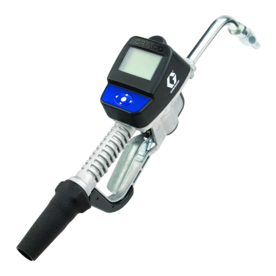
INSTRUCTIONS
®
Matrix
Meter
For dispensing oils and antifreeze over wireless communication with a Matrix system.
For professional use only.
Not approved for use in European explosive atmosphere locations.
Maximum Working Pressure: 1500 psi (10 MPa, 103 bar)
Maximum Flow Rate:14 gpm (53.0 lpm)
Important Safety Instructions
Read all warnings and instructions in this
manual. Save these instructions.
NOTICE
This dispense valve is designed to dispense
petroleum-based lubricants and antifreeze only.
Do not dispense windshield washer solvent with
this dispense valve.
5 & Matrix
®
15
Matrix 5 and Matrix 15 contain an RF device with the
following approval:
FCC ID: TFB-FREESTAR
IC: 5969A-FREESTAR
ABN 75082 447 194
Freestar3 ZFSM-101-3(LSR)
313046T
EN
ti11821s
Advertisement
Table of Contents

Related Manuals for Graco Matrix 5


Summary of Contents for Graco Matrix 5
- Page 1 This dispense valve is designed to dispense petroleum-based lubricants and antifreeze only. Do not dispense windshield washer solvent with this dispense valve. ti11821s Matrix 5 and Matrix 15 contain an RF device with the following approval: FCC ID: TFB-FREESTAR IC: 5969A-FREESTAR ABN 75082 447 194...
- Page 2 Models Models All meters are preset to Quarts in the Graco factory. Matrix 5 Models Model No. Swivel Extension Non-Drip Nozzle Fluid 256282 1/2” NPT(F) Rigid Automatic, Quick Close Oil, ATF 256482 1/2” NPT(F) Flexible Automatic, Quick Close Oil, ATF 256483 1/2”...
-
Page 3: Battery Safety
Warnings Warnings The following warnings are for the setup, use, grounding, maintenance, and repair of this equipment. The exclama- tion point symbol alerts you to a general warning and the hazard symbol refers to procedure-specific risk. Refer back to these warnings. Additional, product-specific warnings may be found throughout the body of this manual where applicable. -
Page 4: Personal Protective Equipment
Warnings WARNING PERSONAL PROTECTIVE EQUIPMENT Wear appropriate protective equipment when in the work area to help prevent serious injury, including eye injury, hearing loss, inhalation of toxic fumes, and burns. Protective equipment includes but is not limited to: • Protective eyewear, and hearing protection. •... -
Page 5: Meter Overview
Meter Overview Meter Overview Navigation and Modes Meter Display Adjusting Screen Contrast using ARROWS On the Main Utility Setup Screen (page 6), use the LEFT and RIGHT ARROWS to adjust the screen contrast. Darken the Screen: Press the RIGHT ARROW •... -
Page 6: Registering The Meter
Registering the Meter Registering the Meter Graco recommends registering the meter prior to If this has not been done first, the software will display installation. an error when attempting to set up meter. NOTE: Before registering the meter, use the Matrix PC Main Utility Setup Screens (F . -
Page 7: Register Screen
Registering the Meter REGISTER Screen D. WRENCH Icon: Returns user to Main Utility Screen. Use the LEFT or RIGHT ARROWS to move the cursor over the WRENCH Icon on the display. Then press REGISTER center, ENTER button on meter’s keypad, to confirm the selection. - Page 8 Registering the Meter e. The meter resets and returns to it’s initial screen. NOTE: If the meter is not able to communicate with the PC during registration, the message NO SIGNAL or NO PC SIGNAL appears on the meter display. NO SIGNAL message means: •...
- Page 9 RF Test RF Test 4. Use RIGHT ARROW to move cursor over START . 7). An RF Test is performed before a Matrix System and meters are installed at a site to evaluate the strength of TEST RF the RF signal and determine the number of Transceivers that will be needed and where they should be installed in the facility.
- Page 10 NOTE: The meter is programmed to try sending a signal the software is released or a new feature is added. to the Transceiver 5 times before displaying the BAD When this is required, your Graco distributor will contact SIGNAL message. you to arrange the upgrade.
- Page 11 Emergency 2. The Emergency Screen appears. The cursor is already in position for entering the first number of the Emergency Code. Use the UP or DOWN ARROWS to scroll through the numbers 0-9 until the first number of the unique Emergency Code assigned to that meter appears in the field.
-
Page 12: Installation
The typical installation shown in F . 13 is only a guide. Hose reel fluid inlet hose It is not a complete system design. Contact your Graco Hose reel distributor for assistance in designing a system to suit A Thermal Relief Kit (not shown) is required. The kit your needs. -
Page 13: Pressure Relief Procedure
. 15) Grounding An Oil Bar Kit is available for mounting one to three meters. See your Graco Distributor or contact Graco Customer Service for ordering details. FIRE HAZARD: Conductive metal surfaces on the meter must not make contact with any positively... -
Page 14: Installation Procedure
Installation Installation Procedure 1. Relieve pressure, page 13. NOTICE • If this is a new installation or if the fluid lines are contaminated, flush the lines before you install the metered valve. Contaminated lines could cause the valve to leak. •... -
Page 15: Impact Guard Kit (24W327)
Installation Installing Tube Extension (F . 17) NOTE: • Only tighten nozzle with wrench on flats of the nozzle bushing. • Do not disassemble the bushing from noz- zle. Disassembly will affect performance of the nozzle. 2. Open automatic twist lock nozzle and all fluid shut-off valves. -
Page 16: Battery Indicator
Setup Setup Battery Indicator MOBIL 1 5W-20 A battery icon appears on the upper right corner of most Setup and Dispense screens. When the batteries are PIN CODE fully charged, the battery will be completely filled in. As the battery discharges, the amount of battery that is 2 1 2 2 filled in will decline. - Page 17 Setup 2. Press the UP or DOWN ARROWS to scroll through 2. After sending the request, the message PLEASE the numbers 0-9. When the correct numeral WAIT appears at the top of the screen as shown in appears in the field, press center ENTER button on .
-
Page 18: Work Orders And Job Codes
Setup Work Orders and Job Codes On the meter, use the UP or DOWN ARROWS to scroll through the list of entered work orders. Refer to the Matrix 3 Software manual for instructions on creating and sending Work Orders and Job Codes using MOBIL1 5W-20 the PC and/or Global Work Orders. - Page 19 Setup To Display PC Created Work Order on the Creating Work Order at the Meter (F . 28) Meter: Using the UP ARROW displays the numbers, 0 - 9 and then alphabet letters, A - Z. By using the DOWN The screen shown in F .
- Page 20 Setup center ENTER button on the meter’s keypad. This new work order now appears as the first item in the Work Order Queue. 7. The work order selection screen displays. You can either select the work order you just created or use the UP or DOWN ARROWS to scroll through the list of all work orders in the queue until you find the work order that applies to the vehicle you are servic-...
- Page 21 Dispense Dispense The meter dispense options are determined by the 4. When you have finished the dispense, press the System Administrator at the time the meter is center ENTER button on the meter’s keypad to programmed. Meter dispense options include: select END (F .
- Page 22 Dispense 3. The display changes to show the Preset Amount. b. PRESET - returns meter to PRESET mode and continues the current preset dispense where it The UP or DOWN ARROWS can be used to was stopped. increase or decrease this amount. If you change the amount you must press the center ENTER c.
-
Page 23: Restricted Preset Dispense
Dispense 1. To TOP OFF, press the center ENTER button on the meter’s keypad to select TOP OFF on the display (the cursor will automatically be positioned over this option when the meter clicks off). 2. Squeeze trigger to dispense additional fluid. The amount dispensed on the display will continue to count up. -
Page 24: Troubleshooting
Unit needs to be calibrated for the Calibrate the meter for the fluid that is accurate. fluid that is being dispensed. being dispensed. Meter leaks from cover/control. Poor seal at metering cover chamber. Contact your Graco distributor for repair or replacement. 313046T... - Page 25 Troubleshooting Problem Cause Solution Meter leaks from twist lock nozzle. Twist lock nozzle has a damaged Replace nozzle. See Step 1 in Instal- seal. lation Procedure, page 15. • It is important to distinguish Valve has damaged or obstructed Clean valve stem o-rings. between the two causes of this seals.
-
Page 26: Error Codes
Ensure that your flow rate is not Switch Error: Error occurred with higher than 14 gpm (37.8 lpm). For pick-up in internal gear. further assistance, contact your Graco distributor. Error 2 Unit was dropped or unit encountered End Dispense excessive vibration during shipping. -
Page 27: Replacing The Battery
Service Service Replacing the Battery • Only use the size and type of batteries specified in this manual. Battery Batteries required to meet life expectancy: Orientation • Energizer E91 • Be sure to follow the correct polarity when installing batteries in the battery compartment . - Page 28 Notes Notes 313046T...
-
Page 29: Meter Parts
Meter Parts Meter Parts Part Description Part Description 15T369 BOOT, swivel, 3/4” hose, NPT and 115477 SCREW, mach, torx pan hd BSPT,green 255889 KIt, repair, trip rod, includes 3a-3c 15T370 BOOT, swivel, 3/4” hose,NPT and and instruction manual 312944 BSPT, yellow BALL,5 MM, carbide 125961 BOOT, swivel, SD, BSPP, black 126115 BOOT, swivel,SD, BSPP,, red... - Page 30 Meter Parts Torque to 15-25 IN. LBS Torque to 20-30 FT. LBS 17 / 47 ti10617b 313046T...
-
Page 31: Nozzle (33) And Extension (20) Kits
Nozzle (33) and Extension (20) Kits Nozzle (33) and Extension (20) Kits Part No. Description Fluid Type Automatic, quick close, non-drip nozzle with 255852* Oil, ATF rigid extension. ti11827 ti11826 Automatic, quick close, non-drip nozzle with 255853* Oil, ATF ti11827 flexible extension ti11825 Quick close, non-drip nozzle with rigid... - Page 32 Nozzle (33) and Extension (20) Kits Part No. Description Fluid Type High flow, quick close, non-drip nozzle with Oil, ATF, 255857 rigid extension Anti-freeze ti11829 ti11826 High flow, quick close, non-drip nozzle with Oil, ATF, 255858 flexible extension Anti-freeze ti11829 ti11825 313046T...
-
Page 33: Nozzle (33) Kits
Nozzle (33) and Extension (20) Kits Nozzle (33) Kits 255459* Automatic, quick-close non-drip, nozzle • BODY, nozzle • O-RING, packing • SPRING, compression • O-RING, packing • STEM, nozzle, valve • SEAT, valve 255460* Quick close, , non-drip, quick-close nozzle Anti-freeze •... - Page 34 Nozzle (33) and Extension (20) Kits Part No. Description PSI (bar) Rating 237893 Mini Fire-Ball 300, 5:1 and Fire-Ball 425, 6:1 900 psi (62 bar) Mini Fire-Ball 300, 5:1 and Fire-Ball 425, 6:1 248296 (same as 237893 without bung adapter and 900 psi (62 bar) swivel.
-
Page 35: Technical Specifications
Technical Specifications Technical Specifications Flow range* ..... 0.1 to 14 gpm (0.4 to 53 lpm) Maximum Working Pressure ......1500 psi (103.4 bar) Units of Measure . -
Page 36: Graco 7-Year Meter And Valve Warranty
With the exception of any special, extended, or limited warranty published by Graco, Graco will, for a period from the date of sale as defined in the table below, repair or replace equipment covered by this warranty and determined by Graco to be defective.
Need help?
Do you have a question about the Matrix 5 and is the answer not in the manual?
Questions and answers