Table of Contents
Advertisement
Advertisement
Table of Contents

Related Manuals for Jungheinrich EMC 110/B 10


Summary of Contents for Jungheinrich EMC 110/B 10
- Page 1 EMC 110/B 10 06.96- Operating instructions 10003627 07.08...
- Page 2 Used to indicate standard equipment. Used to indicate optional equipment. Our trucks are subject to ongoing development. Jungheinrich reserves the right to alter the design, equipment and technical features of the truck. No guarantee of particular features of the truck should therefore be inferred from the present operating instructions.
-
Page 4: Table Of Contents
Table of contents Correct use and application of the truck ......... A 1 Description of the truck ..............B 1 Application ......................B 1 Description of the assemblies and functions ............ B 2 Truck ......................... B 3 Technical data - standard version ..............B 4 Performance data for standard trucks .............. - Page 5 Maintenance of the fork-lift truck ............. F 1 Operational safety and environmental protection ..........F 1 Safety regulations applicable to truck maintenance ......... F 1 Maintenance checklist ..................F 3 Hydraulic oil level ....................F 4 Fuels, coolants and lubricants ................F 4 Notes regarding maintenance ................
- Page 6 Appendix JH Traction Battery Operating Instructions These operating instructions apply only to Jungheinrich battery models. If using another brand, refer to the manufacturer's operating instructions.
-
Page 8: A Correct Use And Application Of The Truck
A Correct use and application of the truck The “Guidelines for the Correct Use and Application of Industrial Trucks” (VDMA) are included in the scope of delivery for this truck. The guidelines are part of these ope- rating instructions and must always be heeded. National regulations are fully applica- ble. -
Page 10: B Description Of The Truck
B Description of the truck Application The truck is intended for transporting goods on a level floor. It can pick up pallets that are open to the ground or trolleys. The capacity of the truck can be found on the capacity label Qmax. -
Page 11: Description Of The Assemblies And Functions
Description of the assemblies and functions Item EMC/EMB Designation Collision protection button Mast covering Weighing system Battery discharge monitor Charge control lamp Battery charging plug (integrated battery charger, 24 V / 9 A) Emergency stop plug Load lifting device Load-bearing wheel Supporting wheel Drive wheel Front hood... -
Page 12: Truck
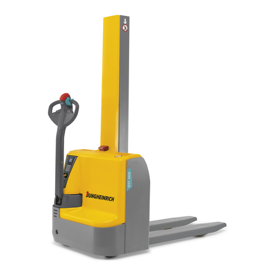
Truck Construction: The EMC/EMB is a four-wheel truck with a steerable drive wheel (11), a supporting wheel (10) and two load-bearing wheels (9). Hoods that are easy to open (2, 12 and 13) provide easy access to all units. The operating controls are located in the control shaft head. -
Page 13: Technical Data - Standard Version
Technical data - standard version Technical data specified according to VDI 2198. Technical data are subject to alteration and additions. Performance data for standard trucks Designation EMC / EMB Rated load capacity 1000 Load centre Travelling speed with / without load 3.5 / 4 km/h Lifting speed with / without load... -
Page 15: Batteries And Motor Output
Batteries and motor output EMC/EMB Battery 2x 12 V / 60 Ah or 55 Ah in series Motor output 0.35 kW EN standards Continuous sound level: 66 dB(A) according to prEN 12053 as stipulated in ISO 4871 The continous sound level is an average value determined according to standard sti- pulations and covers the noise level during driving, during lifting and during idling. -
Page 16: Labels
Labels Xxxx Xxxx Xxxx Xxxxxxx Xxxxxx Xxxxxx Xxxxxx Xxxxxxxx Xxxxxxx Xxxxxx Xxxxxx Xxxxxx Xxxxxx Xxxxxxxxxxxxxx Xxxxxxxxxxxxxxx Xxxxxxx Xxxxxxxxx Xxxxxxxxxxxxxxxxxxx Xxxxxxxxxxxxxxxxxxxx Xxxxxxxxxx Xxxxxxxxxxxxxxxxx Xxxxxxxxxxxxxxxxxxxxx Xxxxxxxxx Xxxxxxxxxxxxxxxxxxxxxxxxx Xxxxxxxxxxxxxxxxxxx Xxxxxxxxx Xxxxxxxxxxxxxxxxxx Xxxxxxxxxxxxxxxxxxxx Xxxxx Xxxxxxxxxxxxxxxxxx Xxxxx Xxxxxxxxxxxxxxxxxx Xxxxx Xxxxxxxxxxxxxxxxxxxxxx Xxxxx Xxxxxxxxxxxxxxxxxx Xxxxxxx Xxxxxxxxxx Xxxxxx Xxxxxxxxx Kundendienst Regelmäßige Prüfung... -
Page 17: Truck Identification Plate
Truck identification plate Xxxx Xxxx Xxxx Xxxxxxx Xxxxxx Xxxxxx Xxxxxx Xxxxxxxx Xxxxxxx Xxxxxx Xxxxxx Xxxxxx Xxxxxx Xxxxxxxxxxxxxx Xxxxxxxxxxxxxxx Xxxxxxx Xxxxxxxxx Xxxxxxxxxxxxxxxxxxx Xxxxxxxxxxxxxxxxxxxx Xxxxxxxxxx Xxxxxxxxxxxxxxxxx Xxxxxxxxxxxxxxxxxxxxx Xxxxxxxxx Xxxxxxxxxxxxxxxxxxxxxxxxx Xxxxxxxxxxxxxxxxxxx Xxxxxxxxx Xxxxxxxxxxxxxxxxxx Xxxxxxxxxxxxxxxxxxxx Xxxxx Xxxxxxxxxxxxxxxxxx Xxxxx Xxxxxxxxxxxxxxxxxx Xxxxx Xxxxxxxxxxxxxxxxxxxxxx Xxxxx Xxxxxxxxxxxxxxxxxx Xxxxxxx Xxxxxxxxxx Xxxxxx Xxxxxxxxx... -
Page 18: C Transportation And Commissioning
C Transportation and commissioning Transportation by crane Only use lifting gear of adequate capacity (loading weight = dead weight + battery weight; see truck identification plate). A lifting eye (1) is provided on the fork side of the mast for loading the truck using crane gear. -
Page 19: Moving An Incapacitated Truck (Emergency Operation)
Moving an incapacitated truck (emergency operation) To move the truck by emergency operation, the electromagnetically applied brake must be released. - Remove the motor cover (2). - Turn the screws (3) in clockwise direction until reaching the stop. The truck can now be moved. After the truck has been parked at its destination, the screws (3) must be turned again anti-clockwise by 1½... -
Page 20: Battery Types
D Battery - Servicing, recharging, replace- ment Safety regulations governing the handling of lead-acid batteries The truck must be parked and rendered safe before any operations on batteries are undertaken (refer to chapter E). Servicing staff: Recharging, servicing and replacing of batteries must only be performed by qualified personnel. -
Page 21: Charging The Battery Using The Integrated Charger
Charging the battery using the integrated charger The mains cable of the charger is accessible from outside. - Pull the mains plug (1) out of the receptacle (2) on the charger and plug it into a suitable electric outlet (220 - 240V ±10%). When flashing green (possibly yellow steady on) the LED (3) indicates that the charger is connected to mains. -
Page 22: Replacing The Batteries
Charging times Depending on the state of discharge, charging the battery can take up to 11 h. Partial charging The charger is designed in such a manner that it automatically adapts itself when charging partially charged batteries. This keeps battery wearing down. Red flashing of LED (3) means that the battery is defective or the charging circuit has been interrupted. - Page 23 Installation is in the reverse order. When installing the battery, make sure that it is in the correct position and that the batteries are correctly connected: - red cable: + terminal of the 1st battery - blue cable: - terminal of the 2nd cable - After the battery has been reinstalled, check all cable connections and plugged connections for visible damage.
-
Page 24: E Operation
E Operation Safety regulations governing the operation of the fork-lift truck Driving permission: The fork-lift truck must only be operated by persons who have been trained in the operation of trucks, who have demonstrated to the user or his representative their capability of moving and handling loads, and who have expressly been charged by the user or his representative with the operation of the truck. -
Page 25: Description Of The Operating Controls And Indicators
Description of the operating controls and indicators Item Control or indicator EMC/EMB Function Collision protection button The truck moves away from the operator. Controller Controls the direction and speed of travel. Button “Lift load lifting device” For lifting the load lifting device. Button “Lower load lifting For lowering the load lifting device”... -
Page 27: Starting Up The Truck
Starting up the truck The driver must make sure that nobody is within the danger area of the truck before the truck is switch on or operated or before a load is lifted. Checks and operations to be performed before starting daily work - Check the entire truck (especially the wheels and the load lifting device) for damage. -
Page 28: Operation Of The Fork-Lift Truck
Operation of the fork-lift truck Safety regulations applicable when operating the truck Driving lanes and work areas: Only such lanes and routes that are specially allocated for truck traffic must be used. Unauthorized persons must stay away from work areas. Loads must only be stored at places specially provided for this purpose. Driving conduct: The travelling speed must be adapted to the prevailing local conditions. -
Page 29: Driving, Steering, Braking
Driving, steering, braking It is not admissible to stay on the vehicle during driving. Emergency stop - Pull out the emergency stop plug (9). All of the electrical functions are switched off. Automatic braking Releasing the control shaft causes automatic braking - the control shaft automatically moves into the upper braking range (B). - Page 30 Braking The braking behaviour of the truck strongly depends on the state of the floor. This must be taken into account by the driver for his driving behaviour. The truck can be braked in three ways: - by using the generator brake (controller (2)) - by counter-current braking (controller (2)) - by using the service brake (control shaft (12)) Braking using the generator brake:...
-
Page 31: Picking Up And Setting Down Loads
Picking up and setting down loads Before picking up a load, the driver must make sure that the load rests properly on its pallet and that it does not exceed the maximum load capacity of the truck. Picking up long loads crosswise is not permitted. - Move the truck so that the load lifting device passes completely below the load. -
Page 32: Emb Wheel Arm Ajustment
EMB wheel arm adjustment Adjust the right- and left-hand wheel arms one after the other. Make sure that both wheel arms are pulled out evenly. The wheel arms can be adjusted in steps of 25 mm. - Protect the truck from rolling away and use a lifting jack at the jack-up point (13) to lift one side of the truck. -
Page 34: F Maintenance Of The Fork-Lift Truck
F Maintenance of the fork-lift truck Operational safety and environmental protection The checks and servicing operations contained in this chapter must be performed in accordance with the intervals as indicated in the servicing checklists. Modifications of fork-lift truck assemblies, especially of the safety installations, are not permitted. - Page 35 Work on the electric system: Work on the electric system of the truck must only be performed by staff specially trained for such operations. Before commencing any work on the electric system, all measures required to prevent electric shocks have to be taken.
-
Page 36: Maintenance Checklist
Maintenance checklist To ensure the safety and service life of the truck, the items listed in the maintenance checklist must be carried out every 1000 service hours, or at least annually. Check all load bearing elements for damage Chassis / superstructure: Check all bolted connections Drive unit:... -
Page 37: Hydraulic Oil Level
Hydraulic oil level Filler plug for hydraulic oil 1,4 l 2,0 l Fuels, coolants and lubricants Handling consumption-type material: Consumption-type material must always be handled properly. Manufacturer’s instructions are to be observed. Improper handling is injurious to health, life and environment. Consumption-type materials must be stored in adequate containers. -
Page 38: Notes Regarding Maintenance
Notes regarding maintenance Preparing the truck for maintenance work All the required safety measures must be taken in order to prevent any accidents in the course of maintenance work. Before starting work, prepare the truck as follows: - Park the truck and render it safe (see chapter E, section 4.5). - Pull out the emergency stop plug (1). -
Page 39: Recommissioning The Truck
Recommissioning the truck Recommissioning the truck following cleaning or maintenance work is permitted only after the following operations have been performed: - Check the brake for correct functioning. - Check the horn for correct functioning. Decommissioning the truck If the truck is to be decommissioned for more than six months (e.g. due to organisational reasons), it must be parked in a frost-free and dry location and all measures to be taken before, during and following decommissioning must be performed as detailed below. -
Page 40: Recommissioning The Truck After Decommissioning
Carry out a safety check in accordance with national regulations. Junheinrich recommends checks in accordance with FEM Guideline 4.004. Jungheinrich has a special safety department with trained personnel to carry out such checks. The truck must be inspected at least annually (refer to national regulations) or after any unusual event by a qualified inspector. -
Page 41: Fault Localisation And Identification
Faul localisation and identification 10.1 Fault localisation Fault Possible cause Remedial action Truck does - Battery plug not - Check and, if necessary, connect the not move connected battery plug - Key switch in vertical - Move the key in clockwise direction until position reaching the stop - Battery charge... -
Page 42: Circuit Diagram
The flash or light codes have the following meaning: Flash or light Possible cause Fault elimination code - Switch the truck off and on again using the key switch. - Control logic not OK - Replace the control system. - Switch off the truck. - The controller was actuated - Set the controller to the while switching on... - Page 43 Legend for the circuit diagram Drive motor 13 2nd driving stage / potentiometer Charger 14 Emergency reversal Pump motor 15 Horn Main fuse 16 Lifting Control fuse 17 Lowering Key-operated switch 18 Pump contactor Accidental starting protection 19 Lowering valve Control shaft switch 20 Control system Battery monitor...
-
Page 44: G Attachments
G Attachments Crane hook Proper use Using approved fastening gear, the electric control shaft fork lift truck EMB with crane hook can be used for lifting and transporting loads. Pulling or pushing of loads atta- ched to the crane hook is not permitted. Before commissioning the truck, make sure that the bolt that fixes the crane arm is properly secured! Loads may only be lifted and transported if they do not exceed the permitted load... -
Page 45: Technical Data Of The Emb With Crane Hook
Technical data of the EMB with crane hook Technical data according to VDI 2198. Technical data are subject to alterations and additions. Performance data of the EMB with crane hook Designation Rated load capacity Load centre Travelling speed with/without load 3.5 / 4 km/h Lifting speed speed with/without load... - Page 46 500 600 800 986 1173 1350 b 1 / b 2 The maximum height of the completely lifted crane hook is 3490 mm. Observe the height of passageways!
-
Page 47: Labels
Labels The following labels differ from the EMC/EMB standard version: - Load diagram - Load capacity label Qmax - Truck identification plate Load diagram “Load capacity / load centre / crane hook” The load diagram indicates the load capacity Q kg of the crane hook. -
Page 48: Operating The Emb With Crane Hook
Operating the EMB with crane hook Observe the safety regulations for driving (see chapter E, section 4.1). Driving, steering and braking see chapter E, section 4.2. Lifting and lowering loads - Attach approved lifting gear to the load. - Fasten the lifting gear to the crane hook. - Lift the load. -
Page 49: Platform
Platform Proper use The platform has been designed as a moveable working table to be used in con- junction with the EMC/EMB. It is not allowed to transport goods on the platform! Technical data 1200 Label 77900041 Typ: Eigengewicht: Herstell-Nr.: ESP: Herstellungs- 1000... -
Page 50: Moving The Platform
Moving the platform - Move the truck with its load lifting device completely underneath the platform. The fastening cam (12) of the platform must be positioned directly above the recess for the load-bearing wheel on the load lifting device. - Lift the platform. Before moving the platform, make sure that the fastening cam (12) engages in the recess for the load-bearing wheel! - Move the platform to its destination and lower it. -
Page 51: Platform With Rollers
Platform with rollers Proper use The platform with rollers has been designed as a moveable roller conveyor to be used in conjunction with the EMC/EMB. Transporting goods on the platform is only allowed if the stoppers are swung down! Technical data 1200 Label 77900042... -
Page 52: Moving The Platform With Rollers
Moving the platform with rollers - Move the truck with its load lifting device completely underneath the platform. The fastening cam (13) of the platform must be positioned directly above the recess for the load-bearing wheel on the load lifting device. Lift the platform. -
Page 53: Automatic Height Positioning Unit
Automatic height positioning unit Correct use and application The automatic height positioning function unit is used to move a loading aid to a freely selectable height that can be comfortably accessed. Positioning occurs according to one of the two states: - „Loading“... -
Page 54: Technical Data
Technical Data Designation Dimension Working height 800-1930 Range Working with the automatic height positioning unit Do not step below a lifted load. Always wear safety boots when working with the automatic height positioning unit. - Pick up the loading aid to be used and park the truck in the work area. - Position the sensor (14) on the side of the mast according to the desired working height. -
Page 55: Adjusting The Sensor
Adjusting the sensor Proceed as follows to adjust the sensitivity of the sensor: - Pick up the load at the required distance. - Lift the pallet/loading aid to the height of the sensor (switch in position „0“). - Loosen the screw (18) and remove the cover (17). - Watch the LED (16). - Page 56 Jungheinrich traction battery Table of contents Jungheinrich traction battery ..........2-6 with positive tubular plates type EPzS and EPzB Type plate Jungheinrich traction battery..........7 Instruction for use ............8-12 Aquamatic/BFS III water refilling system Jungheinrich traction battery Maintenance free traction batteries with positive tubular plates type EPzV ....................13-17...
-
Page 57: Jungheinrich Traction Battery
Jungheinrich traction battery with positive tubular plates type EPzS and EPzB Rating Data 1. Nominal capacity C5: See type plate 2. Nominal voltage: 2,0 V x No of cells 3. Discharge current:: C5/5h 4. Nominal S.G. of electrolyte* Type EPzS:... - Page 58 Ignoring the operation instructions, repair with non-original parts or using additives for the electrolyte will render the warranty void. For batteries in classes I and II the instructions for maintaining the appropriate protection class during operation must be complied with (see relevant certificate). 1.
- Page 59 Battery container lids and the covers of battery compartments must be opened or re- moved. The vent plugs should stay on the cells and remain closed. With the charger switched off connect up the battery, ensuring that the polarity is cor- rect.
- Page 60 3. Maintenance 3.1 Daily Charge the battery after every discharge. Towards the end of charge the electrolyte level should be checked and if necessary topped up to the specified level with purified water. The electrolyte level must not fall below the anti-surge baffle or the top of the separator or the electrolyte „min“...
- Page 61 5. Storage If batteries are taken out of service for a lengthy period they should be stored in the fully charged condition in a dry, frost-free room. To ensure the battery is always ready for use a choice of charging methods can be made: 1.
-
Page 62: 7. Type Plate, Jungheinrich Traction Battery
7. Type plate, Jungheinrich traction battery Baujahr T ype Year of manufacture Serien-Nr. Lieferanten Nr. Serial-Nr. Supplier No. Nennspannung Kapazität Nominal V oltage Capacity Zellenzahl Batteriegewicht min/max Number of Cells Battery mass min/max Hersteller Jungheinrich AG, D-22047 Hamburg, Germany Manufacturer... -
Page 63: Aquamatic/Bfs Iii Water Refilling System
Aquamatic/BFS III water refilling system for Jungheinrich traction battery with EPzS and EPzB cells with tubular positive plates Aquamatic plug arrangement for the Operating Instructions Cell series* Aquamatic plug type (length) EPzS EPzB Frötek (yellow) (black) 2/120 – 10/ 600 2/ 42 –... - Page 64 Diagrammatic view Equipment for the water refilling system 1. Water tank 2. Level switch 3. Discharge point with ball valve 4. Discharge point with sole- noid valve 5. Charger 6. Sealing coupler 7. Closing nipple 8. Ion exchange cartridge with conductance meter and solenoid valve 9.
- Page 65 4. Filling (manual/automatic) The batteries should be filled with battery water as soon as possible before the battery charging comes to an end; this ensures that the refilled water quantity is mixed with the electrolyte. In normal operation it is usually sufficient to fill once a week. 5.
- Page 66 8. Battery hose connections Hose connections for the individual plugs are laid along the existing electric circuit. No changes may be made. 9. Operating temperature The temperature limit for battery operation is set at 55° C. Exceeding this temperature damages the batteries. The battery filling systems may be operated within a tempe- rature range of >...
- Page 67 10.2.1 Clamping ring tool The clamping ring tool is used to push on a clamping ring to increase the contact pres- sure of the hose connection on the plugs' hose couplings and to loosen it again. 10.3 Filter element For safety reasons a filter element (ident no.: 50307282) can be fitted into the batte- ry's main supply pipe for supplying battery water.
-
Page 68: Jungheinrich Traction Battery
Jungheinrich traction batterie Maintenance free Jungheinrich traction batterie with positive tubular plates type EPzV and EPzV-BS Rating Data 1. Nominal capacity C5: See type plate 2. Nominal voltage: 2,0 Volt x No of cells 3. Discharge current: C5/5h 4. Rated temperature: 30°... - Page 69 Ignoring the operation instructions, repair with non-original parts and non authorised interventions will render the warranty void. For batteries in classes I and II the instructions for maintaining the appropriate protection class during operation must be complied with (see relevant certificate). 1.
- Page 70 With the charger switched off connect up the battery, ensuring that the polarity is cor- rect (positive to positive, negative to negative). Now switch on the charger. When charging the temperature of the battery rises by about 15° C, so charging should only begin if the battery temperature is below 35°...
- Page 71 3.2 Weekly Visual inspection after recharging for signs of dirt and mechanical damage. 3.3 Quarterly After the end of the charge and a rest time of 5 h following should be measured and recorded: • the voltages of the battery •...
-
Page 72: 7. Type Plate, Jungheinrich Traction Battery
Batteries with this sign must be recycled. Batteries which are not returned for the recycling process must be disposed of as hazardous waste! We reserve the right make technical modification. 7. Type plate, Jungheinrich traction battery Baujahr T ype Year of manufacture Serien-Nr.
Need help?
Do you have a question about the EMC 110/B 10 and is the answer not in the manual?
Questions and answers