Brocade Communications Systems DCX 8510-8 Hardware Reference Manual
Backbone
Hide thumbs
Also See for DCX 8510-8:
- Hardware installation manual (190 pages) ,
- Hardware reference manual (176 pages) ,
- Reference manual (370 pages)

Related Manuals for Brocade Communications Systems DCX 8510-8


Summary of Contents for Brocade Communications Systems DCX 8510-8
- Page 1 53-1002180-03 ® 28 July 2011 Brocade DCX 8510-8 Backbone Hardware Reference Manual...
- Page 2 Export of technical data contained in this document may require an export license from the United States government. The authors and Brocade Communications Systems, Inc. shall have no liability or responsibility to any person or entity with respect to any loss, cost, liability, or damages arising from the information contained in this book or the computer programs that accompany it.
-
Page 3: Table Of Contents
Nonport side of the Brocade DCX 8510-8 ....4 Brocade DCX 8510-8 blades ....... . 6 High availability . - Page 4 In this chapter ......... . . 21 Configuring the Brocade DCX 8510-8 ......21 Establishing a serial connection to the Brocade DCX 8510-8 .
- Page 5 Faulty CP blade indicators......68 Recording critical Brocade DCX 8510-8 information..68 Removing a control processor blade (CP8) .
- Page 6 Time and items required ....... 99 Faulty Brocade DCX 8510-8 chassis indicators... . . 99 Recording critical Brocade DCX 8510-8 and SAN information .
- Page 7 Troubleshooting.........138 Appendix D Port Numbering Template Index Brocade DCX 8510-8 Backbone Hardware Reference Manual 53-1002180-03...
- Page 8 Brocade DCX 8510-8 Backbone Hardware Reference Manual 53-1002180-03...
- Page 9 Blower assembly ........... 55 Figure 14 WWN bezel (logo plate) with LEDs for DCX and DCX 8510-8 ....57 Figure 15 Removal and replacement of the chassis door .
- Page 10 FX8-24 extension blade ..........146 Brocade DCX 8510-8 Backbone Hardware Reference Manual...
- Page 11 Table 10 WWN LED patterns for DCX and DCX 8510-8 ......57 Table 11 Steps for upgrading through multiple versions of Fabric OS.
- Page 12 Brocade DCX 8510-8 Backbone Hardware Reference Manual 53-1002180-03...
-
Page 13: About This Document
Brocade DCX 8510-8 Backbone (“Brocade DCX 8510-8”). This document presents information on setting up and operating the Brocade DCX 8510-8. It is organized in a loosely chronological order, beginning with an overview of the Brocade DCX 8510-8 and ending with removal and replacement procedures of field replaceable units (FRUs). -
Page 14: Supported Hardware And Software
• Aggregate trunking speed has been corrected. “Brocade DCX 8510-8 features” • The number of Brocade DCX 8510-8 chassis that can be connected with inter-chassis links has been corrected. “Brocade DCX 8510-8 features” • Switch policy setting information has been added for users doing a power supply upgrade. -
Page 15: Command Syntax Conventions
NOTE A note provides a tip, guidance or advice, emphasizes important information, or provides a reference to related information. ATTENTION An Attention statement indicates potential damage to hardware or data. Brocade DCX 8510-8 Backbone Hardware Reference Manual 53-1002180-03... -
Page 16: Notice To The Reader
ID and password. For practical discussions about SAN design, implementation, and maintenance, you can obtain Building SANs with Brocade Fabric Switches through: http://www.amazon.com Brocade DCX 8510-8 Backbone Hardware Reference Manual 53-1002180-03... -
Page 17: Other Industry Resources
Serial console and Telnet session logs • syslog message logs 2. Brocade DCX 8510-8 serial number The Brocade DCX 8510-8 serial number (Switch Serial No.) and corresponding bar code are provided on the serial number label, as shown here: *FT00X0054E9* FT00X0054E9... -
Page 18: Esd Precautions
The Brocade DCX 8510-8 contains electrostatic discharge (ESD) sensitive FRUs. When working with any Brocade DCX 8510-8 FRU, use correct ESD procedures. • Wear a wrist grounding strap connected to chassis ground (if the Brocade DCX 8510-8 is plugged in) or a bench ground. •... - Page 19 In this chapter documentation@brocade.com Provide the title and version number and as much detail as possible about your comment, including the topic heading and page number and your suggestions for improvement. Brocade DCX 8510-8 Backbone Hardware Reference Manual 53-1002180-03...
- Page 20 In this chapter Brocade DCX 8510-8 Backbone Hardware Reference Manual 53-1002180-03...
-
Page 21: Overview
Brocade DCX 8510-8 features ........ -
Page 22: Brocade Dcx 8510-8 Hardware Components
Two slots for control processor blades (CP8): A single active CP8 blade can control all 384 ports in the chassis. The standby CP8 blade assumes control of the Brocade DCX 8510-8 if the active CP fails. • Two slots for core switch blades (CR16-8): CR16-8 blade interconnects all port blades. -
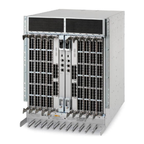
Page 23: Port Side Of The Brocade Dcx 8510-8
Constant intake and FRU temperature monitoring. Port side of the Brocade DCX 8510-8 NOTE Airflow in the Brocade DCX 8510-8 is from the nonport (noncable) side to the port (cable) side and out the exhaust vent. Figure 1 displays a sample configuration of the port side of the Brocade DCX 8510-8. -
Page 24: Nonport Side Of The Brocade Dcx 8510-8
Cable management comb Control processor blade (CP8) FIGURE 1 Port side of the Brocade DCX 8510-8 (sample configuration) Nonport side of the Brocade DCX 8510-8 The following figure shows a sample configuration of the nonport side view of the Brocade DCX 8510-8. -
Page 25: Figure 2 Nonport Side Of The Brocade Dcx 8510-8 (Sample Configuration)
Brocade DCX 8510-8 hardware components WWN bezel (logo plate - WWN card behind) Blower assembly Power supply FIGURE 2 Nonport side of the Brocade DCX 8510-8 (sample configuration) Brocade DCX 8510-8 Backbone Hardware Reference Manual 53-1002180-03... -
Page 26: Brocade Dcx 8510-8 Blades
A 32-port Brocade port blade supporting 2, 4, 8, 10, and 16 Gbps blade Fibre Channel port speeds. The blade also supports port-based in-flight encryption/decryption and compression/decompression. This port blade is compatible with the Brocade DCX 8510-8 and Brocade DCX 8510-4. 48-port 16-Gbps port FC16-48... -
Page 27: Reliability
CP failover activity, closes and flushes streams, provides flow control and message buffering, and supports a centralized active and standby state. Reliability The Brocade DCX 8510-8 uses the following error detection and correction mechanisms to ensure reliability of data: •... -
Page 28: Software Features
Security Table 2 highlights some of the key security features available for the Brocade DCX 8510-8 and for other Brocade enterprise-class products running Fabric OS 7.0.0 or later. For details, contact your Brocade DCX 8510-8 supplier and refer to the Brocade White Paper, “The Growing Need for Security in Storage Area Networks.”... -
Page 29: Table 2 Brocade Security Features
Hardware-enforced zoning by WWN, domain/port ID, or both Default zoning RSCN suppression and aggregation Configurable RSCN suppression by port NTPv3 (to synchronize timestamps) Event auditing Change tracking Firmware change alerts in Fabric Manager Brocade DCX 8510-8 Backbone Hardware Reference Manual 53-1002180-03... -
Page 30: Network Manageability
E_Port disable Network manageability The Brocade DCX 8510-8 has a single domain and is managed as a single element with the Brocade Network Advisor. The Brocade DCX 8510-8 responds to its own IP address and appears as a separate entity to the Telnet protocol and SNMP. -
Page 31: In This Chapter
Items included with the Brocade DCX 8510-8......15 • Providing power to the Brocade DCX 8510-8 ......15 •... -
Page 32: Preparing For Brocade Dcx 8510-8 Installation
8510-8 accessory kit). Establishing serial connection, logging on 20 minutes Serial cable (provided in the accessory kit). to Brocade DCX 8510-8, and configuring IP Workstation computer with a serial port or addresses terminal server port and a terminal emulator application (such as HyperTerminal). - Page 33 (17.22 in.) wide. 1U is equal to 4.45 cm (1.75 in.). Plan to install the Brocade DCX 8510-8 with the nonport side facing the air-intake aisle. The Brocade DCX 8510-8 can be installed facing either direction, if serviceability and cooling requirements are met.
-
Page 34: Unpacking And Installing The Brocade Dcx 8510-8
Use safe lifting practices when moving the product. (C015) NOTE A fully populated Brocade DCX 8510-8 (eight FC16-48 port cards, 384 ports) weighs approximately 159.2 kg (351 lbs) and requires a hydraulic or assisted lift to install it. 1. Unpack the Brocade DCX 8510-8. -
Page 35: Items Included With The Brocade Dcx 8510-8
14U Rack Mount Kit with instructions (includes rear brackets and bottom support rails) Order the optical transceivers (SFP+, mSFP, and QSFP) from Brocade. The Brocade DCX 8510-8 supports SWL, LWL, and ELWL transceivers. The mSFPs and QSFPs are SWL transceivers only. -
Page 36: Port Numbering
Use of the high-voltage line (200 to 240 VAC) is highly recommended because of better power-conversion efficiency. A DCX 8510-8 chassis fully loaded with 16 Gbps port blades (384 ports total) should be supplied with four power supplies connected to 200-240 VAC lines. -
Page 37: Chassis Slots
Chassis slots are numbered 1 through 12, from left to right when facing the port side of the Brocade DCX 8510-8. Control processor blades (CP8) can be installed only in slots 6 and 7. Core switch blades (CR16-8) can be installed only in slots 5 and 8. The rest of the slots, 1–4 and 9–12, can be filled with port, application, or encryption blades. -
Page 38: High Density Cabling
ISL Trunking group: eight ports marked with solid black ovals alternate with eight ports marked with oval outlines. See the appendix for a listing of supported cable speeds and distances. Brocade DCX 8510-8 Backbone Hardware Reference Manual 53-1002180-03... -
Page 39: Installing Qsfp Cables (Optional)
Managing cables Installing QSFP cables (optional) “Inter-chassis link (QSFP) cable removal and replacement” on page 95 for the procedure to install the QSFP cables Brocade DCX 8510-8 Backbone Hardware Reference Manual 53-1002180-03... - Page 40 Managing cables Brocade DCX 8510-8 Backbone Hardware Reference Manual 53-1002180-03...
-
Page 41: Logging In And Configuring The Brocade Dcx 8510-8
In this chapter • Configuring the Brocade DCX 8510-8 ......21 •... -
Page 42: Figure 4 Configuration Tasks
CP blade fails. The configuration information for the Brocade DCX 8510-8 is stored in the WWN cards and the flash memory of the CP blades. The configuration can be backed up to a workstation (uploaded) and then downloaded to the active CP blade if necessary. -
Page 43: Establishing A Serial Connection To The Brocade Dcx 8510-8
To establish a serial connection to the console port on the Brocade DCX 8510-8, complete the following steps. 1. Verify that the Brocade DCX 8510-8 is powered on and that POST is complete by verifying that all power LED indicators on the port, control processor, and core switch blades display a steady green light. -
Page 44: Logging In To The Serial Console Port
To log in to the Brocade DCX 8510-8 through the serial connection, follow these steps. 1. Log in to the Brocade DCX 8510-8 as admin. The default password is password. At the initial login, you are prompted to enter new admin and user passwords. Make sure to write down the new passwords and keep this information in a secure location. -
Page 45: Serial Cable
NOTE The addresses 10.0.0.0 through 10.0.0.255 are reserved and used internally by the Brocade DCX 8510-8. External IPs must not use these addresses. 3. Set up the CP0 IP address by entering the ipaddrset -cp 0 command: swDir:admin> ipAddrSet -cp 0 Enter the information at the prompts. -
Page 46: Customizing A Switch Name
Customizing a switch name The switch name of the Brocade DCX 8510-8 can be up to 30 characters long using Fabric OS release 6.3.0 or later; can include letters, numbers, hyphens, and underscore characters; and must begin with a letter. -
Page 47: Setting The Domain Id
Setting the date To set the date, follow these steps. 1. If necessary, log on to the Brocade DCX 8510-8 by Telnet, using the admin account. The default password is password. 2. Enter the date command, using the following syntax: date "mmddHHMMyy"... -
Page 48: Setting The Time Zone
3. Enter the appropriate number or Ctrl-D to quit. 4. At the prompt, select a country location. 5. At the prompt, enter the appropriate number to specify the time zone region or Ctrl-D to quit. Brocade DCX 8510-8 Backbone Hardware Reference Manual 53-1002180-03... -
Page 49: Synchronizing Local Time
Verifying the PID mode Before connecting the Brocade DCX 8510-8 to the fabric, verify that the port identifier (PID) mode on the Brocade DCX 8510-8 matches the other switches in the fabric. This parameter must be identical for all switches in the fabric and is set using the configure command. -
Page 50: Installing Transceivers And Attaching Cables
Follow these steps to install SFP+s and mSFPs (FC8-64 port card only) and cables to the Brocade DCX 8510-8. Follow the second set of steps to install the QSFP transceivers and cables in the core blades for inter-chassis link connections. - Page 51 Repeat steps 1 and 2 for the remaining ICL 3. Organize the cables See “Managing Cables.” 4. Verify the Brocade DCX 8510-8 and connector and port status using the switchShow -qsfp command. A sample of the command output is shown below. The example is from a DCX 8510-4 with a core blade installed in slot 3.
-
Page 52: Managing Cables
Leave at least 1 m (3.28 ft) of slack for each port cable. This provides room to remove and replace the Brocade DCX 8510-8, allows for inadvertent movement of the rack, and helps prevent the cables from being bent to less than the minimum bend radius. -
Page 53: Verifying Correct Operation And Backing Up The Configuration
This command provides information about switch and port status. 4. Verify the correct operation of the Brocade DCX 8510-8 in the fabric by entering the fabricShow command from the workstation. This command provides general information about the fabric. -
Page 54: Powering Off The Brocade Dcx 8510-8
NOTE It is recommended that the configuration be backed up on a regular basis to ensure that a complete configuration is available for downloading to a replacement Brocade DCX 8510-8. Powering off the Brocade DCX 8510-8 Perform the following steps to power off the Brocade DCX 8510-8. -
Page 55: Chapter 4 Monitoring System Components
DCX 8510-8. These commands are switchShow and chassisShow. Examples of these commands are shown below. Note in the switchShow command the new switchType for the Brocade DCX 8510-8 as well as the 16 Gbps speed identification for capable ports. The output has been truncated to reduce information duplication. - Page 56 1 xge0 No_Light FCIP 1 xge1 No_Light FCIP 782000 No_Light 782100 No_Light 782200 No_Module 782300 No_Light 782400 No_Module 782500 No_Module 782600 No_Module 782700 No_Module 782800 No_Light 782900 No_Light 782a00 No_Module 782b00 No_Module Brocade DCX 8510-8 Backbone Hardware Reference Manual 53-1002180-03...
- Page 57 782c80 No_Module 782d80 No_Module 782e80 No_Module 782f80 No_Module 783000 No_Light 783100 No_Light 783200 No_Light 783300 No_Light 783400 No_Light 783500 No_Light 783600 No_Light 783700 No_Light 783800 No_Light 783900 No_Light 783a00 No_Light 783b00 No_Light Brocade DCX 8510-8 Backbone Hardware Reference Manual 53-1002180-03...
- Page 58 ------ No_Module ------ No_Module ------ No_Module ------ No_Module ------ No_Module ------ No_Module ------ No_SigDet ------ No_SigDet ------ No_SigDet ------ No_SigDet ------ No_SigDet ------ No_SigDet ------ No_SigDet ------ No_SigDet ------ No_SigDet ------ No_SigDet Brocade DCX 8510-8 Backbone Hardware Reference Manual 53-1002180-03...
- Page 59 1174 ------ No_Module <output truncated> DCX_8510_8:root> Note in the chassisShow command the Chassis Family designation for the Brocade DCX 8510-8 along with specific information about every field-replaceable unit in the chassis. DCX_8510_8:root> chassisshow Chassis Family: DCX8510-8 Chassis Backplane Revision: 0...
- Page 60 Factory Part Num: 60-1002140-02 Factory Serial Num: BPZ0349F006 Manufacture: Day: Month: 12 Year: 2010 Update: Day: 28 Month: Year: 2011 Time Alive: 46 days Time Awake: 0 days SW BLADE Slot: 11 Brocade DCX 8510-8 Backbone Hardware Reference Manual 53-1002180-03...
- Page 61 Power Consume Factor: -126 Factory Part Num: 60-1000384-09 Factory Serial Num: AGB0652E0H9 Manufacture: Day: 29 Month: 12 Year: 2009 Update: Day: 28 Month: Year: 2011 Time Alive: 319 days Time Awake: 0 days Brocade DCX 8510-8 Backbone Hardware Reference Manual 53-1002180-03...
-
Page 62: Determining The Status Of A Port Or Application Blade
The LED patterns may temporarily change during POST and other diagnostic tests. For information about how to interpret the LED patterns, see the table following the blade descriptions. 2. Check the blade status by entering slotShow. Brocade DCX 8510-8 Backbone Hardware Reference Manual 53-1002180-03... -
Page 63: Blade Illustrations
Fibre Channel port Power LED Port Status LED FIGURE 5 FC8-64 Port blade NOTE The FC8-64 port blade requires narrower OM-3 LC cables offered by major manufacturers like Corning, Molex, and Amphenol. Brocade DCX 8510-8 Backbone Hardware Reference Manual 53-1002180-03... -
Page 64: Figure 6 Fc16-32 Port Blade
Determining the status of a port or application blade Power LED Fibre Channel port Status LED Port status LED FIGURE 6 FC16-32 Port blade Brocade DCX 8510-8 Backbone Hardware Reference Manual 53-1002180-03... -
Page 65: Figure 7 Fc16-48 Port Blade
Determining the status of a port or application blade Power LED Fibre Channel port Status LED Port status LED FIGURE 7 FC16-48 Port blade Brocade DCX 8510-8 Backbone Hardware Reference Manual 53-1002180-03... -
Page 66: Figure 8 Fs8-18 Encryption Blade
Determining the status of a port or application blade Power LED Fibre Channel port Status LED Port Status LED FIGURE 8 FS8-18 Encryption blade Brocade DCX 8510-8 Backbone Hardware Reference Manual 53-1002180-03... -
Page 67: Figure 9 Fx8-24 Extension Blade
10GbE port 0 Status LED 10GbE port 0 LED GbE port 6 Port map GbE port 6 LED FIGURE 9 FX8-24 Extension blade “FX8-24 blade” for information about trunking groups on this blade. Brocade DCX 8510-8 Backbone Hardware Reference Manual 53-1002180-03... -
Page 68: Table 4 Port And Application Blade Led Descriptions
2 is faulty. If LED continues to flash, seconds) replace the blade. Fast-flashing amber (on Environmental range exceeded. Check for out-of-bounds 1/2 second, then off 1/2 environmental condition and second) correct it. Brocade DCX 8510-8 Backbone Hardware Reference Manual 53-1002180-03... - Page 69 Port is online, with traffic No action required. flowing through port. Fast-flashing amber Transceiver or port is faulty. Change the transceiver or reset (on 1/4 second, then the switch from the workstation. off 1/4 second) Brocade DCX 8510-8 Backbone Hardware Reference Manual 53-1002180-03...
-
Page 70: Determining The Status Of A Control Processor Blade (Cp8)
CP8 blade. Power LED Console port (Serial) Status LED Ethernet port (Mgmt IP) USB LED Ethernet port (Service IP) USB port Active CP LED FIGURE 10 Control processor blade (CP8) Brocade DCX 8510-8 Backbone Hardware Reference Manual 53-1002180-03... -
Page 71: Determining The Status Of A Core Switch Blade (Cr16-8)
No light (LED is off) Standby CP blade. No action required. Determining the status of a core switch blade (CR16-8) Complete the following steps to determine the status of a core switch blade (CR16-8). Brocade DCX 8510-8 Backbone Hardware Reference Manual 53-1002180-03... -
Page 72: Figure 11 Core Switch Blade (Cr16-8)
QSFP port map and trunking diagram Status LED QSFP connectors FIGURE 11 Core switch blade (CR16-8) Table 6 describes the core switch blade LED patterns and the recommended actions for those patterns. Brocade DCX 8510-8 Backbone Hardware Reference Manual 53-1002180-03... -
Page 73: Determining The Status Of A Power Supply
1. Check the LED indicator on the power supply (see the following figure). The LED patterns may temporarily change during POST and other diagnostic tests; for information about how to interpret the LED patterns, see the table below. The Brocade DCX 8510-8 has four power supplies. Be sure to check each module. -
Page 74: Determining The Status Of A Blower Assembly
1. Check the LED indicators on the blower assembly (see the following figure). The LED patterns may temporarily change during POST and other diagnostic tests; for information about how to interpret the LED patterns, see the table below. The Brocade DCX 8510-8 has three blowers. Be sure to check each module. -
Page 75: Figure 13 Blower Assembly
If a blower assembly displays absent or faulty, contact the Brocade DCX 8510-8 supplier to order replacement parts. Both physically absent or faulty could also be the result of the power supply not being properly seated. -
Page 76: Determining The Status Of A Wwn Card
The WWN bezel covers the WWN cards and allows its LEDs to shine through. The LEDs on the WWN bezel provide a consolidated view of the port, CP, and CR blade status. Brocade DCX 8510-8 Backbone Hardware Reference Manual 53-1002180-03... -
Page 77: Figure 14 Wwn Bezel (Logo Plate) With Leds For Dcx And Dcx 8510-8
CR blade Status (above) and Power (below) LEDs Slot numbers FIGURE 14 WWN bezel (logo plate) with LEDs for DCX and DCX 8510-8 Table 10 describes the WWN card LED patterns and the recommended actions for those patterns. Brocade DCX 8510-8 Backbone Hardware Reference Manual... - Page 78 Determining the status of a WWN card Brocade DCX 8510-8 Backbone Hardware Reference Manual 53-1002180-03...
-
Page 79: Removal And Replacement Procedures
Inter-chassis link (QSFP) cable removal and replacement ....95 • Brocade DCX 8510-8 chassis removal and replacement ....99 Introduction... -
Page 80: Removing A Chassis Door
2. Push the door into place. It will snap onto the studs. Cable management comb removal and replacement The Brocade DCX 8510-8 can continue to operate during the replacement of the cable management comb. Brocade DCX 8510-8 Backbone Hardware Reference Manual... -
Page 81: Time And Items Required
3. Unscrew and save the four (4) screws holding the comb to the chassis. Support the comb to prevent it from falling. 4. Remove the cable management comb. FIGURE 16 Removal and replacement of the cable management comb Brocade DCX 8510-8 Backbone Hardware Reference Manual 53-1002180-03... -
Page 82: Replacing A Cable Management Comb
Slots are numbered from 1 through 12, from left to right when facing the port side of the Brocade DCX 8510-8. Port, application, and encryption blades can be installed in slots 1 through 4 and 9 through 12. - Page 83 The FC8-64 port blade, the FS8-18 encryption blade and the FX8-24 application blade are compatible only with the Brocade DCX, DCX-4S, DCX 8510-8, and DCX 8510-4.The FC16-32 and FC16-48 port blades are compatible only with the DCX 8510-8 and DCX 8510-4.
-
Page 84: Replacing A Blade
Removal and replacement of the port, application, and encryption blades (FC16-48 port blade shown) Replacing a blade For this procedure, refer to Figure Complete this procedure to replace a blade. ATTENTION Follow electrostatic discharge (ESD) precautions while replacing any blade. Brocade DCX 8510-8 Backbone Hardware Reference Manual 53-1002180-03... -
Page 85: Blade Filler Panel Removal And Replacement
Any slot that is not occupied by a blade should be occupied by a filler panel to ensure correct cooling of the chassis and protection from dust. Brocade DCX 8510-8 Backbone Hardware Reference Manual 53-1002180-03... -
Page 86: Replacing A Filler Panel
3. Using the tabs, pull the filler panel out of the chassis. FIGURE 18 Removal and replacement of the blade filler panel Replacing a filler panel Do not leave a slot empty. This will adversely affect cooling of the chassis. Brocade DCX 8510-8 Backbone Hardware Reference Manual 53-1002180-03... -
Page 87: Control Processor Blade (Cp8) Removal And Replacement
NOTE For the DCX 8510-8 , slots are numbered from 1-12 from left to right, viewed from the port side of the chassis. There are several references to additional Brocade manuals in this document. To access them online, go to this location on the MyBrocade web site, http://my.brocade.com/wps/myportal/!ut/p/c1/04_SB8K8xLLM9MSSzPy8xBz9CP0os3gnN8cwY... -
Page 88: Faulty Cp Blade Indicators
Control processor blade (CP8) removal and replacement • Serial cable. • IP address of an FTP server for backing up the Brocade DCX 8510-8 configuration. • #2 Phillips screwdriver. • Replacement Brocade DCX 8510-8 control processor blade (CP8). • If you are upgrading through multiple versions of the Fabric OS, consult the “Steps for upgrading through multiple versions of Fabric OS”... - Page 89 If automatic failover has not occurred, manually failover the faulty blade by moving the slider to the off position (down in the DCX 8510-8). Then power off the faulted blade, log in to standby CP blade, and skip to step 7.
-
Page 90: Removing A Control Processor Blade (Cp8)
6. Disconnect all cables from the faulty (standby) CP. Unscrew the thumb screw from both ejectors using the Phillips screwdriver. 8. Lever open both ejector handles simultaneously to approximately 45 degrees and pull the CP blade out of the chassis. Brocade DCX 8510-8 Backbone Hardware Reference Manual 53-1002180-03... -
Page 91: Replacing A Control Processor Blade (Cp8)
CP blade and upgrading it if necessary. For this procedure, please refer to “ESD precautions” Figure Complete the following steps to remove a CP8 control blade (CP). Brocade DCX 8510-8 Backbone Hardware Reference Manual 53-1002180-03... -
Page 92: Verifying Operation Of The New Cp Blade
NOTE The DCX 8510-8 requires Fabric OS 7.0.0 or later to be recognized. If the firmware on the replacement blade is earlier than 7.0.0 it must be brought up to the version on the active CP blade, which must be at least 7.0.0. -
Page 93: Table 11 Steps For Upgrading Through Multiple Versions Of Fabric Os
The -s option also disables the autoreboot, so you will have to manually issue a reboot after the download finishes to initiate firmwarecommit. Enter all requested information (use default values). There are caveats to using the -f option. Read the following information carefully. Brocade DCX 8510-8 Backbone Hardware Reference Manual 53-1002180-03... - Page 94 CP. The internal firmware image is relocated successfully. Firmware has been downloaded to the secondary partition of the switch. 2010/06/18-14:44:04, [SULB-1002], 904,, INFO, Brocade_DCX, Firmwaredownload command has completed successfully. Brocade DCX 8510-8 Backbone Hardware Reference Manual 53-1002180-03...
- Page 95 Otherwise, proceed to step Log out of the standby CP blade and log in to the active CP blade. 8. Proceed to “Complete the replacement.” Brocade DCX 8510-8 Backbone Hardware Reference Manual 53-1002180-03...
- Page 96 The -U option indicates that the download should come from the USB device. If you do not use this option, you are prompted with Download from USB [No}: Type Y to download from the USB device. Enter all requested information using default values. Brocade DCX 8510-8 Backbone Hardware Reference Manual 53-1002180-03...
- Page 97 CP. The internal firmware image is relocated successfully. Firmware has been downloaded to the secondary partition of the switch. 2010/06/18-14:44:04, [SULB-1002], 904,, INFO, Brocade_DCX, Firmwaredownload command has completed successfully. Brocade DCX 8510-8 Backbone Hardware Reference Manual 53-1002180-03...
- Page 98 Otherwise, proceed to step 10. Log out of the standby CP blade and log in to the active CP blade. 11. Proceed to “Complete the replacement.” Brocade DCX 8510-8 Backbone Hardware Reference Manual 53-1002180-03...
-
Page 99: Complete The Replacement
8510-8 has two core switch blades: one in slot 5 and one in slot 8. Note that the blade shown in the removal illustration (Figure 20) is shown with EMI plugs installed. Brocade DCX 8510-8 Backbone Hardware Reference Manual 53-1002180-03... -
Page 100: Time And Items Required
For more information about error messages, refer to the Fabric OS Message Reference. Removing a core switch blade (CR16-8) The Brocade DCX 8510-8 continues to operate while a core switch blade is being replaced. Refer to Figure 20 for the following procedure. -
Page 101: Replacing A Core Switch Blade (Cr16-8)
FIGURE 20 Removal and replacement of the core switch blade (CR16) Replacing a core switch blade (CR16-8) Complete the following steps to replace the core switch blade. Brocade DCX 8510-8 Backbone Hardware Reference Manual 53-1002180-03... -
Page 102: Power Supply Removal And Replacement
Use this procedure to remove and replace a power supply. NOTE Depending on the blade configuration of the chassis and the number of power supplies installed, the Brocade DCX 8510-8 may be able to continue operating during the replacement. See “Power specifications”... -
Page 103: Removing A Power Supply
1. Perform the appropriate following action based on whether the Brocade DCX 8510-8 is operating: • If the Brocade DCX 8510-8 is not operating during the replacement procedure, go to step • If the Brocade DCX 8510-8 is operating and will continue to operate during the replacement, check the power LEDs to verify that the minimum number of power supplies is functioning. -
Page 104: Replacing A Power Supply
Verify that the power LED on the power supply displays a steady green light. 8. If you are installing two new power supplies in a DCX or DCX 8510-8 chassis to bring the total of power supplies up to four, you should change the switchstatus policy settings for power... -
Page 105: Blower Assembly Removal And Replacement
Use this procedure to remove and replace a blower assembly. ATTENTION The Brocade DCX 8510-8 can continue operating during the replacement if the other two blower assemblies are operating, To ensure continuous adequate cooling, maintain three operating blower assemblies at all times except for the brief period when replacing a blower assembly. -
Page 106: Replacing A Blower Assembly
Use this procedure to remove and replace a WWN card. NOTE The World Wide Name (WWN) cards contain fully redundant circuits and normally do not require replacement. Two WWN cards are located beneath the WWN bezel (logo plate). Brocade DCX 8510-8 Backbone Hardware Reference Manual 53-1002180-03... -
Page 107: Time And Items Required
0x24c (fabos): Switch: switchname, Error accessible. EM-WWN_ABSENT, 2, WWN #1 not present Writing to the FRU history log 0x24c (fabos): Switch: switchname, Error (hilSetFruHistory) has failed. EM-HIL_FAIL, 2, HIL Error: hilSetFruHistory failed, rc=-3 for SLOT 3 Brocade DCX 8510-8 Backbone Hardware Reference Manual 53-1002180-03... -
Page 108: Removing The Wwn Card And Wwn Bezel (Logo Plate)
CR blade Status (above) and Power (below) LEDs Slot numbers FIGURE 24 WWN bezel (logo plate) with LEDs for DCX and DCX 8510-8 Table 10 describes the WWN card LED patterns and the recommended actions for those patterns. Removing the WWN card and WWN bezel (logo plate) - Page 109 9. Disconnect the WWN cable by depressing the cable connector latch and pulling the connector from the WWN module. 10. Set the WWN card on a static-free surface, such as a grounding pad. Brocade DCX 8510-8 Backbone Hardware Reference Manual 53-1002180-03...
-
Page 110: Replacing The Wwn Card And Wwn Bezel (Logo Plate)
3. In the CLI session, enter continue to indicate that the replacement has been completed. Please enter the word `continue' after the new WWN card has been installed: continue Brocade DCX 8510-8 Backbone Hardware Reference Manual 53-1002180-03... -
Page 111: Transceiver Removal And Replacement
Most Brocade switches and backbones come with a transceiver extraction tool (Figure 1) and holster. The extraction tool is designed to remove transceivers from switches and blades where the space is limited. Brocade DCX 8510-8 Backbone Hardware Reference Manual 53-1002180-03... -
Page 112: Removing An Sfp+ Transceiver
16 Gbps SFP+ from the switch or blade. See the illustration for the mSFP transceiver for the basic appearance of the 16 Gbps transceiver. SFP/XFP bail FIGURE 27 Replacing an optical transceiver Brocade DCX 8510-8 Backbone Hardware Reference Manual 53-1002180-03... -
Page 113: Replacing An Sfp+ Transceiver
Use this procedure to remove and replace mSFP transceivers. Do not use the extraction tool to remove the transceivers. NOTE The mSFP transceivers are used only with the FC8-64 port blade. Narrower OM-3 LC cables are used to connect the FC8-64. Brocade DCX 8510-8 Backbone Hardware Reference Manual 53-1002180-03... -
Page 114: Figure 29 Optical Msfp Transceiver
2. Remove the cable from the transceiver. Pull tab mSFP transceiver FIGURE 29 Optical mSFP transceiver Replacing an mSFP transceiver For this procedure, refer to Figure Complete the following steps to replace an mSFP transceiver. Brocade DCX 8510-8 Backbone Hardware Reference Manual 53-1002180-03... -
Page 115: Inter-Chassis Link (Qsfp) Cable Removal And Replacement
For the 8510 series models, if the QSFP cables are not used, make sure the rubber gaskets are in the QSFP transceivers. The following table describes the connector port LED patterns and the recommended actions for those patterns. Brocade DCX 8510-8 Backbone Hardware Reference Manual 53-1002180-03... -
Page 116: Time And Items Required
FIGURE 30 QSFP cable and transceiver Time and items Required The replacement procedure for an ICL cable takes less than five minutes. Replacement ICL cable. Brocade DCX 8510-8 Backbone Hardware Reference Manual 53-1002180-03... -
Page 117: Removing An Icl Cable
When the link is fully established, the LED displays steady green. 3. Repeat for each cable that requires replacement. 4. Once all the cables are attached, see the Fabric OS Administrator’s Guide for the configuration procedure. Brocade DCX 8510-8 Backbone Hardware Reference Manual 53-1002180-03... -
Page 118: Possible Icl Configurations
Although 8510-8 chassis are shown in the figure, the chassis can be either 8510-4 or 8510-8. The cabling scheme should follow the parallel example shown in the previous figure. Brocade DCX 8510-8 Backbone Hardware Reference Manual 53-1002180-03... -
Page 119: Brocade Dcx 8510-8 Chassis Removal And Replacement
FIGURE 33 DCX 8510 core/edge ICL topology Brocade DCX 8510-8 chassis removal and replacement This section describes how to remove and replace the Brocade DCX 8510-8 chassis (with its backplane). The basic steps are: Faulty Brocade DCX 8510-8 chassis indicators... -
Page 120: Time And Items Required
Brocade DCX 8510-8 chassis removal and replacement NOTE The Brocade DCX 8510-8 must be removed from the fabric and powered off to perform this procedure. Contact your support provider if you have any questions about whether the chassis requires replacement. -
Page 121: Recording Critical Brocade Dcx 8510-8 And San Information
New factory serial number New serial number (if available) 1. Open a Telnet session and log in to the Brocade DCX 8510-8 as admin. The default password is password. Enable the logging function on your Telnet or serial console connection. - Page 122 Brocade DCX 8510-8 chassis removal and replacement This command uploads the Brocade DCX 8510-8 configuration to the customer-defined FTP server, making it available for downloading. For more information about this command, refer to the Fabric OS Command Reference. switch:admin> configupload Protocol (scp or ftp) [ftp]: ftp Server Name or IP Address [host]: 123.123.123.123...
- Page 123 -qsfp • fabricShow Copy the command output into a text file named “SANbefor.txt.” After the Brocade DCX 8510-8 is restored to the fabric, this information can be used to verify that no unintentional changes have occurred to the fabric.
-
Page 124: Disconnecting From Network And Fabric
This file provides a backup of all the information that might be required by Technical Support. The information can be used after the Brocade DCX 8510-8 is restored to the fabric to verify that no unintentional changes have occurred to the fabric. -
Page 125: Removing Components From The Chassis
NOTE If the Brocade DCX 8510-8 is installed in a cabinet, ensure that the cabinet is balanced and secured mechanically and that the removal and installation procedure will not compromise cabinet stability. -
Page 126: Installing Components Into The New Chassis
The Brocade DCX 8510-8 performs a power-on self-test (POST). The POST takes a minimum of three minutes and is complete when LED activity returns to standard state. 12. Verify that the Brocade DCX 8510-8 is powered on and POST is complete (all power LED indicators on the blades should be a steady green). -
Page 127: Downloading The Configuration
The configDownload command can be entered through a Telnet or serial session, but the Brocade DCX 8510-8 must have an Ethernet connection to the server name or IP address of the host for the download process to complete. - Page 128 FC16-48 ENABLED SW BLADE FC8-64 ENABLED switch:admin> 3. Verify that the Brocade DCX 8510-8 is functioning correctly by entering switchShow or switchStatusShow. This switchShow command displays the Brocade DCX 8510-8 and port status information. switch:FID128:admin> switchshow switchName: DCX8510_8 switchType: 120.1...
-
Page 129: Reconnecting The System To The Network And Fabric
The Brocade DCX 8510-8 can be accessed by remote connection using any of the available management tools, such as Telnet or Web Tools. Ensure that the Brocade DCX 8510-8 is not modified using other connections during the rest of this procedure. -
Page 130: Verifying Correct Configuration Of The Fabric
• ISL and port states • Number of switches in the fabric 3. Resolve any issues or unintentional changes to the Brocade DCX 8510-8 or fabric: • If there are any mechanical problems, try reseating the associated component. • If the configuration information is not correct for the Brocade DCX 8510-8, modify as required. -
Page 131: Cable Routing Table
64-port template for a cable routing table. Make copies of the table to cover the total number of ports in the Brocade DCX 8510-8. TABLE 16 Cable routing table for Brocade DCX 8510-8 (64 ports shown) Slot/port Cable labels... -
Page 132: Table 16 Cable Routing Table For Brocade Dcx 8510-8 (64 Ports Shown)
Brocade DCX 8510-8 chassis removal and replacement TABLE 16 Cable routing table for Brocade DCX 8510-8 (64 ports shown) (Continued) Slot/port Cable labels Connected device Slot/port of device Slot Port Switch end Device end Brocade DCX 8510-8 Backbone Hardware Reference Manual... - Page 133 Brocade DCX 8510-8 chassis removal and replacement Brocade DCX 8510-8 Backbone Hardware Reference Manual 53-1002180-03...
- Page 134 Brocade DCX 8510-8 chassis removal and replacement Brocade DCX 8510-8 Backbone Hardware Reference Manual 53-1002180-03...
-
Page 135: Specifications
Environmental regulation compliance ......129 General specifications The Brocade DCX 8510-8 is compliant with United States and International safety and Electromagnetic Compatibility (EMC) standards. The following table lists the general specifications for the Brocade DCX 8510-8. -
Page 136: System Architecture
System architecture System architecture The following table describes the system architecture of the Brocade DCX 8510-8. TABLE 18 System architecture Feature Description Fibre Channel Ports Up to 384 16 Gbps ports, universal (E_Port, F_Port, EX_Port, M_Port, D_Port). Control Processor Redundant (active/standby) control processor blades. -
Page 137: System Size And Weight
(ICL/QSFP) System size and weight The weight of the Brocade DCX 8510-8 can vary considerably depending on the combination of blades installed. Use the following table and the System FRU weights table to determine the weight of the Brocade DCX 8510-8 with your combination of port and application blades. -
Page 138: System Blade And Fru Weights
Chassis door 2.09 kg (4.6 lb) Facility requirements The facility where the Brocade DCX 8510-8 is in use must meet the following requirements to provide for correct operation: • Adequate supply circuit, line fusing, and wire size, as specified by the electrical rating on the chassis nameplate. -
Page 139: Environmental Requirements
Watch commands to view temperature status. Fibre Channel port specifications The Fibre Channel ports in the Brocade DCX 8510-8 support full duplex link speeds at 2, 4, 8, 10, or 16 Gbps inbound and outbound, automatically negotiating to the highest common speed of all devices connected to the port. -
Page 140: Power Specifications
The following table shows the power draw for the blades that can be used in the Brocade DCX 8510-8 chassis along with the power draw for the cooling fans. All numbers for the blades assume that the blade is fully populated with optical transceivers, including QSFPs for the core blades. -
Page 141: Power Cords
Power cords The types of power cords provided with the Brocade DCX 8510-8 are specific to the country where it is installed. For each of the types of power cords in the following table, the end that connects to the Brocade DCX 8510-8 has an IEC 60320/C19 cable connector. -
Page 142: Table 25 Power Cord Types (International)
Austria Bahrain Belgium Brazil Chile China, People’s Rep. Czech, Rep. of Denmark Egypt England Finland France Germany Greece Hong Kong Hungary India Indonesia Ireland, North Ireland, South Israel Italy Japan Korea, South Brocade DCX 8510-8 Backbone Hardware Reference Manual 53-1002180-03... - Page 143 Recommended Mexico Monaco Netherlands New Zealand Norway Poland Portugal Puerto Rico Russia Saudi Arabia Scotland Singapore South Africa Spain Sweden Switzerland Taiwan Turkey United Arab Emirate United Kingdom United States Venezuela Yugoslavia Brocade DCX 8510-8 Backbone Hardware Reference Manual 53-1002180-03...
-
Page 144: Power-Cord Notice
Data transmission ranges The following table provides the data transmission ranges for different transceivers, port speeds, and cable types. NOTE There is no LWL or ELWL version of either the mSFP or QSFP transceiver. Brocade DCX 8510-8 Backbone Hardware Reference Manual 53-1002180-03... -
Page 145: Qualified Cables For The Fc8-64 Port Blade
943-99865-10005 multi-mode, OM3, 50/125 mSFP LC - standard LC, duplex, 10 m S50502S5120010M 106273-0529 943-99865-10010 multi-mode, OM3, 50/125 Patch cables - mSFP to mSFP S5S502S5120XXXM 943-99866-1XXXX (XXX = length) (XXXX = length) Brocade DCX 8510-8 Backbone Hardware Reference Manual 53-1002180-03... -
Page 146: Regulatory Compliance
LC - MTP-female, 24 fiber, 106272-0328 12" breakout, OM3, 50/125 Bag of clips (quantity 64) TRIGGER-BP-NP Regulatory compliance This section describes the regulatory compliance requirements for the Brocade DCX 8510-8. It contains the following standards: • “FCC warning (US only)” on page 126 •... -
Page 147: Kcc Statement (Republic Of Korea)
European Council directives, laws, and standards: • Electromagnetic Compatibility (EMC) Directive 2004/108EEC • Low Voltage Directive (LVD) 73/23/EEC and the Complementary Directive 93/68/EEC • EN55022:2006 (European Emissions Requirements) • EN55024:1998, +A1:2001 and +A2:2003 (European Immunity Requirements) Brocade DCX 8510-8 Backbone Hardware Reference Manual 53-1002180-03... -
Page 148: Canadian Requirements
IEC 825-2. Optical products that do not comply with these standards might emit light that is hazardous to the eyes. Regulatory compliance standards The following table lists the regulatory compliance standards for which the Brocade DCX 8510-8 is certified. TABLE 28... -
Page 149: Environmental Regulation Compliance
The EPUP assumes that the product will be used under normal conditions in accordance with the operating manual of the product. (EPUP) EPUP Brocade Brocade ocade EPUP Brocade DCX 8510-8 Backbone Hardware Reference Manual 53-1002180-03... - Page 150 Information products (Decree No. 39 by the Ministry of Information Industry), the following information is provided regarding the names and concentration level of hazardous substances (HS) which may be contained in this product. Brocade DCX 8510-8 Backbone Hardware Reference Manual 53-1002180-03...
- Page 151 Environmental regulation compliance Brocade DCX 8510-8 Backbone Hardware Reference Manual 53-1002180-03...
- Page 152 Environmental regulation compliance Brocade DCX 8510-8 Backbone Hardware Reference Manual 53-1002180-03...
-
Page 153: Appendix B Application And Encryption Blades
FX8-24 blade ..........134 Introduction This appendix provides details about the application and encryption blades that are available optionally for the Brocade DCX 8510-8. Contact your Brocade DCX 8510-8 supplier for additional information. FS8-18 blade... -
Page 154: Fx8-24 Blade
Ten per trunk through the 10 GbE ports. • SO-TCP with reorder resistance. • FastWrite over FCIP. • Tape pipelining over FCIP. • FICON XRC emulation and tape pipelining over FCIP (licensable). • FICON CUP (licensable). Brocade DCX 8510-8 Backbone Hardware Reference Manual 53-1002180-03... - Page 155 Up to three FC trunking groups. The three groups are defined as: • Trunk group 0: FC ports 0,1 • Trunk group 1: FC ports 6,7 • Trunk group 2: FC ports 2,3,4,5,8,9,10,11 Brocade DCX 8510-8 Backbone Hardware Reference Manual 53-1002180-03...
- Page 156 FX8-24 blade Brocade DCX 8510-8 Backbone Hardware Reference Manual 53-1002180-03...
-
Page 157: Appendix C Diagnostics And Troubleshooting
In addition, a number of managing and monitoring features are available, such as Fabric Manager, Web Tools, Fabric Watch, and Advanced Performance Monitoring. If the Brocade DCX 8510-8 does not operate as expected, the following steps can be taken to diagnose the problem: •... -
Page 158: Obtaining Chassis And Component Status
Interpreting POST and boot results The Brocade DCX 8510-8 performs Power On Self Test (POST) by default each time the chassis is powered on, rebooted, or reset. The Brocade DCX 8510-8 can be rebooted using the reboot (to reboot each CP individually) or fastBoot commands. -
Page 159: Boot
1. Universal port configuration is performed. 2. Links are initialized. 3. Fabric is analyzed. If any ports are connected to other switches, the Brocade DCX 8510-8 participates in a fabric configuration. 4. The Brocade DCX 8510-8 obtains a domain ID and assigns port addresses. -
Page 160: Troubleshooting
9600 bits per second, 8 databits, no parity, 1 stop bit, no flow control. Serial port might be incompatible (only Ensure that the Brocade DCX 8510-8 is connected to RS-232 is supported). an RS-232 port. RS-423 serial ports might experience difficulties due to corner-case incompatibilities of the standards. - Page 161 Replace the parts as required. None of the LEDs on a component Component might not be seated correctly. Ensure that the Brocade DCX 8510-8 has power and are on. the component is firmly seated. If the problem continues, enter the sensorShow command to determine the component status.
-
Page 162: Figure 33 Fc8-64 Port Blade
Enter the tempshow and sensorShow command to determine the component status. If the component is a CP blade or port blade, enter the slotShow command to determine the status. Replace the component as necessary Brocade DCX 8510-8 Backbone Hardware Reference Manual 53-1002180-03... -
Page 163: Appendix D Port Numbering Template
Appendix Port Numbering Template Print or copy the following templates in this appendix and use them to document the port numbering pattern for the Brocade DCX 8510-8. These templates show the following components: • FC8-64 high density port blade (Figure •... - Page 164 Blade Status LED port 61 LED Blade Power LED port 29 LED Port 63 FC ports 32-63 (bottom to top) Port 30 FC ports 0-31 (bottom to top) FIGURE 34 FC8-64 port blade Brocade DCX 8510-8 Backbone Hardware Reference Manual 53-1002180-03...
- Page 165 Port Numbering Template Blade Power LED FC ports 16-23 Blade Status LED FC ports 0-7 FC ports 24-31 FC ports 8-15 Port and trunking group map FIGURE 35 FC16-32 port blade Brocade DCX 8510-8 Backbone Hardware Reference Manual 53-1002180-03...
- Page 166 Port Numbering Template Blade Power LED FC ports 24-47 Blade Status LED FC ports 0-23 FIGURE 36 FC16-48 port blade Brocade DCX 8510-8 Backbone Hardware Reference Manual 53-1002180-03...
- Page 167 Port Numbering Template Gigabit Ethernet ports GE0-GE1 Fibre Channel ports 0-15 Smart card port FIGURE 37 FS8-18 encryption blades Brocade DCX 8510-8 Backbone Hardware Reference Manual 53-1002180-03...
- Page 168 Port Numbering Template 10 GbE ports 0-1 FC ports 0-5 1 GbE ports 0-3 Blade Power LED 1 GbE ports 4-9 Blade Status LED FC ports 6-11 FIGURE 38 FX8-24 extension blade Brocade DCX 8510-8 Backbone Hardware Reference Manual 53-1002180-03...
- Page 169 Port Numbering Template Brocade DCX 8510-8 Backbone Hardware Reference Manual 53-1002180-03...
- Page 170 Port Numbering Template Brocade DCX 8510-8 Backbone Hardware Reference Manual 53-1002180-03...
- Page 171 LEDs switchName replacing switchShow status switchShow -qsfp boot results, interpreting sysShutdown BSMI statement (Taiwan) tsClockServer buffers, frame tsTimeZone usbStorage Brocade DCX 8510-8 Backbone Hardware Reference Manual 53-1002180-03...
- Page 172 POST domain ID setting domain IDs troubleshooting encryption blade encryption blade, replacing environmental regulation compliance error messages, WWN card Brocade DCX 8510-8 Backbone Hardware Reference Manual 53-1002180-03...
- Page 173 LEDs FX8-24 blade blower assembly CP blade CR blade port blade power supply GbE ports troubleshooting license, chassis software licenseIdShow command licenseShow command local time, synchronizing high availability logout command humidity, requirement Brocade DCX 8510-8 Backbone Hardware Reference Manual 53-1002180-03...
- Page 174 ANSI serial port logout serviceability, features setting time zone shock, requirement QSFP cables site planning installing size and weight replacing slotShow command QSFP transceivers software features software, features Brocade DCX 8510-8 Backbone Hardware Reference Manual 53-1002180-03...
- Page 175 QSFP replacing supported types troubleshooting chassis power configuration data CP blade domain IDs Ethernet link speed FRUs general IP addresses LEDs port blade serial connection Brocade DCX 8510-8 Backbone Hardware Reference Manual 53-1002180-03...
- Page 176 Brocade DCX 8510-8 Backbone Hardware Reference Manual 53-1002180-03...
Need help?
Do you have a question about the DCX 8510-8 and is the answer not in the manual?
Questions and answers