Table of Contents
Advertisement
Quick Links
Advertisement
Table of Contents

Related Manuals for Air Lift 57397


Summary of Contents for Air Lift 57397
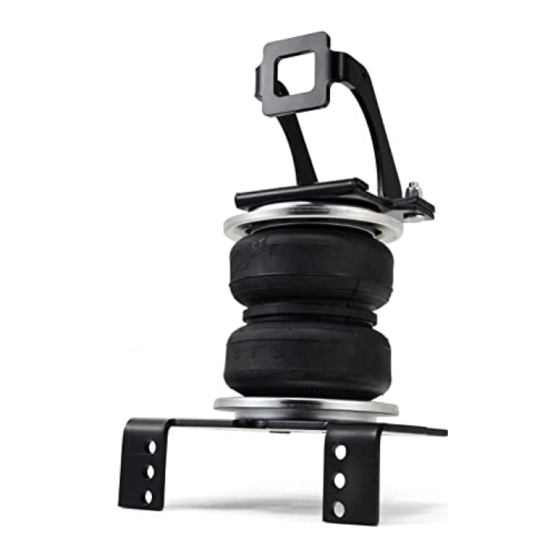
- Page 1 Kit 57397 Ford F-250/F-350 (Single and Dual Rear Wheel) 2-Wheel Drive INSTALLATION GUIDE For maximum effectiveness and safety, please read these instructions completely before proceeding with installation. Failure to read these instructions can result in an incorrect installation.
-
Page 2: Important Safety Notice
LoadLifter 5000 Introduction The purpose of this publication is to assist with the installation, maintenance and troubleshooting of the LoadLifter 5000 air spring kit. LoadLifter 5000 utilizes sturdy, reinforced, commercial grade single or double, depending on the kit, convolute bellows. The bellows are manufactured like a tire with layers of rubber and cords that control growth. -
Page 3: Installation Diagram
LoadLifter 5000 Installation Diagram 5th Wheel 3/4” Flat Washer* or (R) Driver side shown Y or R Bracket (Plate) 3/4” Flat Washer* or (R) 3/4” Nyloc Nut* or (X) 3/4” Bolt* or (O) or (HH) fig. 1 NOTE: Single rear wheel mounting location shown. -
Page 4: Hardware And Tools Lists
LoadLifter 5000 Hardware and Tools Lists HARDWARE LIST Item Part # Description ....... Qty Item Part # Description . -
Page 5: Installing The Loadlifter 5000 System
LoadLifter 5000 Installing the LoadLifter 5000 System GETTING STARTED 1. Raise the vehicle and support the axle with jack stands, setting the jack stands as wide as possible on the axle (fig. 2). Jack Stands fig. 2 2. Remove the jounce bumpers from under the frame, over the axle. 3. - Page 6 LoadLifter 5000 SIDE BRACE INSTALLATION 5th Wheel Driver side shown 3/4” Flat Washer* or (R) Y or R Bracket (Plate) 3/4” Flat Washer* or (R) 3/4” Nyloc Nut* or (X) 3/4” Bolt* or (O) or (HH) fig. 4 1. Set the upper brace (B) into the driver and passenger side frame (fig. 4). If you have a fifth wheel hitch that does not have a plate running alongside the full length of the frame (these will have an “L”...
- Page 7 LoadLifter 5000 BELLOWS AND BRACKET ASSEMBLY 1. Set a roll plate (G) over the top and bottom of the bellows (H) (fig. 1). NOTE The radiused (rounded) edge of the roll plate (G) will be towards the bellows so that the bellows is seated inside both roll plates.
- Page 8 LoadLifter 5000 ATTACHING THE ASSEMBLIES TO THE FRAME 1. If not done so yet, drop the axle or raise the frame up to make room for the assemblies to be put into position. 2. Set the left (driver side) assembly onto the axle (fig. 1). Raise the axle just enough to insert the long carriage bolt (M) (that is installed in the upper bracket) through the existing jounce bumper hole in the bottom of the frame.
- Page 9 LoadLifter 5000 2a.If you are installing this kit on a single rear wheel (SRW) vehicle, use position 2 to insert the long 3/8-16 x 10” carriage bolt (Q) through the top of the locating bracket and lower bracket (fig. 9). 2b.If you are installing this kit on a dual rear wheel (DRW) vehicle, use position 1 to insert the long 3/8-16 x 10”...
-
Page 10: Final Steps
LoadLifter 5000 NOTE For 2WD and 4WD DRW vehicles, in order to install the sway bar and sway bar retaining straps back onto the axle, it will be necessary to slot the retaining straps (fig. 11). Reattach the sway bar once this is done. Grind slot larger Grind slot larger fig. -
Page 11: Installing The Air Lines
LoadLifter 5000 INSTALLING THE AIR LINES 1. Choose a convenient location for mounting the inflation valves. Popular locations for the inflation valve are: a. The wheel well flanges b. The license plate recess in bumper c. Under the gas cap access door d. -
Page 12: Installing The Heat Shield
LoadLifter 5000 Option 1 fig. 15 Option 2 7. Cut off the air line, leaving approximately 12” of extra air line. A clean square cut will ensure against leaks. Insert the air line into the air fitting. This is a push-to-connect fitting. -
Page 13: Product Use, Maintenance And Servicing
The required air pressure will vary depending on the state of the original suspension. Operating the vehicle below the minimum air spring pressure will void the Air Lift warranty. 5. When increasing load, always adjust the air pressure to maintain the normal ride height. -
Page 14: Frequently Asked Questions
4. Look for a kink or fold in the air line. Reroute as needed. If the preceding steps do not solve the problem, it is possibly caused by a failed air spring — either a factory defect or an operating problem. Please call Air Lift at (800) 248-0892 for assistance. Frequently Asked Questions Q . -
Page 15: Guidelines For Adding Air
(fig. 22). As much as a 50 PSI difference is not uncommon. fig. 21 fig. 22 Bottoming out Unlevel Level AIR LIFT SYSTEMS SUSPENSION SYSTEMS...
Need help?
Do you have a question about the 57397 and is the answer not in the manual?
Questions and answers