Table of Contents
Advertisement
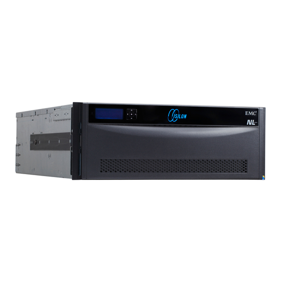
Installation Guide
Isilon
NL400
Install a new node
120-0095-01
REV J
May, 2016
guide.........................................................................................................2
types.................................................................................................................2
compatibility......................................................................................... 2
components.................................................................................. 2
rack............................................................................................ 3
panel.................................................................................................9
panel...............................................................................................................10
supply........................................................................................12
node.................................................................................................. 13
menu.............................................................................................. 16
database..................................................................................... 18
support............................................................................................18
node...................................................................................... 6
network........................................................................ 10
network......................................................................... 11
Advertisement
Table of Contents

Subscribe to Our Youtube Channel
Related Manuals for EMC Isilon NL400


Summary of Contents for EMC Isilon NL400
-
Page 1: Table Of Contents
Installation Guide Isilon NL400 Install a new node 120-0095-01 REV J May, 2016 About this guide......................2 Drive types.........................2 Confirm SSD compatibility..................2 Unpack and verify components.................. 2 Install the node in a rack.................... 3 Install the drives in the node..................6 Install the front panel....................9 Back... -
Page 2: About This Guide
Installation Guide About this guide This guide describes how to install a new EMC Isilon node. You can follow the procedure in this guide to: Install several nodes to create a new cluster. Add a new node to an existing cluster. -
Page 3: Install The Node In A Rack
Install a new node Install the node in a rack Isilon nodes mount in standard ANSI/EIA RS310D 19-inch rack systems and use a sliding rail system to provide easy access to the node. The sliding rail kit is compatible with rack cabinets with the following hole types: 3/8 inch square holes 9/32 inch round holes 10-32, 12-24, M5X.8, or M6X1 pre-threaded holes... - Page 4 Installation Guide 1. Step Alignment Pin for Round-Hole or Square- 2. Shoulder Alignment Pin for Pre- Hole Racks Threaded Racks Procedure 1. Confirm the type of rack you are installing the rails in and replace the alignment pins if necessary. If you are installing the rails in a rack with 3/8 inch square-holes or 9/32 inch round-holes, you do not need to adjust the alignment pins.
- Page 5 Install a new node 1. Outer slide rail 2. Clip-on nut retainer Install the node in the rack Secure the node to the storage rack. CAUTION To minimize the chance of personal injury or equipment damage, and to ensure proper slide rail installation, it is recommended that two people lift and move the node.
-
Page 6: Install The Drives In The Node
Installation Guide 1. Chassis Retaining Screw Results DANGER Do not continue with this procedure until you have confirmed the following: 1. Both rails are secured to the rack and all mounting screws are in place and tightened. 2. The inner slide rails attached to the node are inserted correctly, and firmly secured, in the intermediate slide rails that are attached to the rack. - Page 7 Install a new node 1. Locking handle 2. Drive bay 2. Hold the drive in place and gently push the drive locking handle down against the end of the drive to secure the drive in the drive bay. 3. Repeat the previous steps until the front bays of the node are full. Note Drives that are not fully seated will not be recognized when the node starts, and a red light will appear below the drive.
- Page 8 Installation Guide 1. Rear EMI shield 5. Insert and lock drives into the back bays until they are full. 1. Rear EMI shield 2. Locking handle 3. Drive bay 6. Replace the rear EMI shield. NL400 Installation Guide...
-
Page 9: Install The Front Panel
Install a new node Install the front panel The front panel covers the drives and provides a keypad and LCD, which displays status information. You can use the keypad and LCD to perform basic configuration tasks. Procedure 1. Install the front panel assembly by aligning the front panel with the front of the node and then pressing the front panel onto the node. -
Page 10: Back Panel
5. USB ports 10. InfiniBand internal network ports CAUTION Only trained EMC Isilon personnel should connect to the node with the PS/2, USB or VGA ports. For direct access to the node, connect to the serial port. LEDs Do not rely on LEDs to determine the health of a node or node component. If any hardware component is in an error state, identify and troubleshoot the error through OneFS events and alerts. -
Page 11: Connect The External Client Network
Install a new node 2. If the network topology supports a second internal network, connect the int-b port to a separate network switch for the int-b network. 1. int-a port 2. int-b port Connect the external client network The ethernet cable connects the node to the cluster's external network so the node can communicate with external clients. -
Page 12: Connect The Power Supply
Installation Guide 1. ext-1 port 3. ext-3 or 10gige-1 port 2. ext-2 port 4. ext-4 or 10gige-2 port Connect the power supply Each node contains redundant power supplies to ensure that the node remains powered in case a power supply fails. Procedure 1. -
Page 13: Configure The Node
Install a new node Configure the node Before using the node, you must either create a new cluster or add the node to an existing cluster. SmartLock compliance mode You can configure nodes to operate in SmartLock compliance mode. You should only choose to run your cluster in SmartLock compliance mode if your data environment must comply with SEC rule 17-a4(f). - Page 14 Installation Guide Run the configuration wizard The Isilon configuration wizard starts automatically when a new node is powered on. The wizard provides step-by-step guidance for configuring a new cluster or adding a new node to an existing cluster. The following procedure assumes that there is an open serial connection to a new node. Note You can type at most prompts to return to the previous step in the wizard.
- Page 15 Install a new node Setting Description The default character encoding is UTF-8. int-a network settings The network settings used by the int-a network. The int-a network is used for communication between nodes. Netmask The int-a network must be configured with IPv4. IP range The int-a network must be on a separate subnet from an int-b/failover network.
-
Page 16: Front Panel Lcd Menu
Installation Guide Setting Description Manual join Enables either a configured node in the existing cluster, or a new node, to issue a request to join the cluster. Secure join A configured node in the existing cluster must invite a new unconfigured node to join the cluster. Note If you are installing a node that contains SEDs (self-encrypting drives), the node will format the drives at this time. - Page 17 Install a new node Throughput Displays throughput numbers for the cluster as <in> <out> <total> Node The Node menu contains the following sub-menus: Details Displays the node ID, the node serial number, the health status of the node, and the node uptime as <days>...
-
Page 18: Update The Install Database
Update the install database After all work is complete, update the install database. Procedure 1. Browse to the EMC Product Registration and Install base Maintenance service portal, at: http://emc.force.com/createPSCcase. 2. Select the Product Registration and Install Base Maintenance option. - Page 19 EMC Isilon Community Network. However, if you have purchased one or more licenses of IsilonSD Edge, you can contact EMC Isilon Technical Support for assistance, provided you have a valid support contract for the product. Where to go for support...
- Page 20 2016 EMC Corporation. All rights reserved. Published in the USA. Published May, 2016 EMC believes the information in this publication is accurate as of its publication date. The information is subject to change without notice. The information in this publication is provided as is. EMC Corporation makes no representations or warranties of any kind with respect to the information in this publication, and specifically disclaims implied warranties of merchantability or fitness for a particular purpose.
Need help?
Do you have a question about the Isilon NL400 and is the answer not in the manual?
Questions and answers