Jandy AquaPure Workbook
Hide thumbs
Also See for AquaPure:
- Installation and operation manual (53 pages) ,
- Installation and operation manual (52 pages)
Table of Contents
Advertisement
Advertisement
Table of Contents

Related Manuals for Jandy AquaPure


Summary of Contents for Jandy AquaPure
- Page 1 Jandy AquaPure, PureLink & Nature² Fusion Soft Workbook...
- Page 2 Zodiac Pool Systems, Inc. 1-800-822-7933 www.ZodiacPoolSystems.com Instructor___________________________________________________ ext._________ Sales Representatives________________________________________ ext._________ __________________________________________________________ ext._________ __________________________________________________________ ext._________ Service Manager_____________________________________________ ext._________ __________________________________________________________ ext._________...
-
Page 3: Table Of Contents
- CELL VOLTAGE AND CURRENT ................23 - SERVICE CODE......................24 - SERVICE CODE FLOW CHARTS................25-28 ORIGINAL AQUAPURE, PURELINK, AND CM3 TEST POINTS- - BACK BOARD TRANSFORMER AND CELL VOLTAGE TESTS......... 29 - FRONT BOARD VOLTAGE TESTS ................30 - FRONT BOARD SENSOR READNGS TEST............... 31... -
Page 4: Models And Model Numbers
6613AP Power Pack Model: 6614AP-L= Sub Panel Power Center PureLink for AL-RS/PDA 6613AP= Standard Power Center PureLink Generator for AL-RS/PDA AquaPureM or Nature² FusionM = Stand Alone AquaPure/Nature² Fusion PLC1400 Cell Model: PLC= Cell Kit FSOFT= Cell Kit with Nature2 Vessel... -
Page 5: Sizing And Generation Process
CHLORINE GENERATION Chlorine Production and Process Gas Chlorine Liquid Chlorine 90% Tri-Chlor Calcium Hypochlorite (12.5%) Tabs .625 lbs. .625 gallons .69 lbs. 0.95 lbs. 1400 1.25 lbs 1.25 gallons 1.38 lbs 1.9 lbs. ANODE Hypochlorous Acid Hydrochloric Acid Hypochlorous Acid Sodium Hypochlorite Sodium Chloride (Liquid Chlorine) -
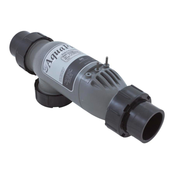
Page 6: Components
CHLORINE GENERATION AQUAPURE AND NATURE² FUSION POWER PACKS STAND ALONE POWER PACK APUREM NATURE² FUSIONM PURELINK POWER CENTERS STANDARD POWER CENTER 6613AP SUB-PANEL POWER CENTER 6614AP-L AquaPure/ Nature² Fusion Soft PureLink Power Pack USER INTERFACE BOARD (UIB) Replacement P/N: R0467400... - Page 7 CHLORINE GENERATION CELL KITS 16’ CORDS PLC700 (Up to 12,000 Gallons) PLC1400 (Up to 40,000 Gallons) 25’ CORDS PLC700-25 PLC1400-25 Low Voltage Cord Flow/Temp/Salinity Cell – 3 Port Sensor NATURE² FUSION SOFT KITS 16’ CORDS FSOFT700 (Up to 12,000 Gallons) FSOFT1400 (Up to 40,000 Gallons) NATURE²...
-
Page 8: Nature²
NATURE² Nature² Nature² Benefits • The Bactericidal qualities of silver reduce the amount of chlorine required to maintain the pool. The copper inhibits algae growth. • By Lowering the output of the chlorine generator, the pool water quality dramatically im- proves and the life of the electrolytic cell is extended. -
Page 9: Installation- - Plumbing
CHLORINE GENERATION INSTALLATION – PLUMBING 3 Port Cell and Sensor Preferred Plumbing The “T” for the Flow/Temp/Salinity Sensor should be pointed down to prevent air entrapment which could cause false readings. 13 7/8” Cut Out 3 Port Cell and Sensor OK Plumbing The 3 Port Cell can be located so the sensor is mounted to the side of the cell. - Page 10 CHLORINE GENERATION INSTALLATION - PLUMBING 3 Port Cell and Sensor Wrong Plumbing If the 3 Port Cell is plumbed as shown, the cell may not produce chlorine, and the sensor will pro- vide inaccurate readings. Wrong 3 Port Cell and Sensor Wrong Plumbing If the 3 Port Cell is plumbed as shown, the sensor may provide inaccurate readings.
-
Page 11: Plumbing
CHLORINE GENERATION INSTALLATION - PLUMBING Nature² Fusion Proper Plumbing The Flow/Temp/Salinity must be plumbed on the inlet side of the Nature² Fusion. 13 7/8” Cut Out 11 1/8” Center of Pipe Notes: _____________________________________________________________________ _____________________________________________________________________ _____________________________________________________________________ _____________________________________________________________________... -
Page 12: Electrical
CHLORINE GENERATION INSTALLATION - ELECTRICAL 1400 To Covert a Power Interface Board (PIB) from a 1400 to a 700 cut the jumper Cell Low Voltage Cable Connection Original Cell Low Cell Low Voltage Cell Low Voltage Voltage Cable Extension Cable Extension Cable Extension wires from... -
Page 13: Electrical
CHLORINE GENERATION INSTALLATION - ELECTRICAL Versa Plumb- 3 Port Cell Connected to load side Cell should be the last item of time clock or relay. on the equipment pad All electrical equipment connected by bond wire. Versa Plumb- Nature² Fusion Soft Connected to load side of time clock or relay. -
Page 14: Chemistry
CHLORINE GENERATION INSTALLATION - CHEMISTRY START-UP Before starting a chlorine generator • Balance the pool water • Super chlorinate if needed. • Add a metal remover. WATER CHEMISTRY • Free chlorine - 1.0 to 3.0 (Low of .5 is possible with the Nature² Fusion) •... -
Page 15: Chemistry
CHLORINE GENERATION INSTALLATION - CHEMISTRY SALT As a general guideline, the purer the salt the better the performance and the longer the “life” of the cell. Calcium and magnesium are the enemies of the cell and cause scaling, poor performance and short- ened anode life. -
Page 16: Operation
JA - indicates operation is controlled by a Jandy AquaLink RS or PDA, and is in AUTO mode. JO - indicates operation is controlled by a Jandy AquaLink RS or PDA, and the system is in SERVICE or TIMEOUT mode. -
Page 17: Troubleshooting - Transformer Voltage
TROUBLESHOOTING - TRANSFORMER VOLTAGE FLOW SENSOR FLOW SENSOR H - Temp H - Temp This test confirms the proper secondary R - Temp Salinity R - Temp Salinity Salinity = 2.8 voltage is coming out of the transformer. Salinity = 2.8 R Temp = 75 POS - 2 H Temp = 91... -
Page 18: Transformer Voltage
TROUBLESHOOTING - TRANSFORMER VOLTAGE +24 VDC VAC 1 +12 VDC 19 VAC +5 VDC VAC 2 COMMON 1 Amp FUSE 1000 200µ 2000µ 200m 200m 2000K 200K 65 VAC 75 VAC Third Test: Set the meter to 200 ACV or higher. Put the leads on VAC 1 & VAC 2 of the 19 VAC test points. -
Page 19: Power Interface Board (Pib) Dc Voltage
TROUBLESHOOTING - PIB DC VOLTAGE FLOW SENSOR FLOW SENSOR H - Temp H - Temp This test confirms that the Power Inter- R - Temp Salinity R - Temp Salinity face Board (PIB) is taking the AC Volt- Salinity = 2.8 R Temp = 75 Salinity = 2.8 POS - 2... -
Page 20: Sensor Inspection
TROUBLESHOOTING - SENSOR INSPECTION FLOW/TEMP/SALINITY SENSOR The Sensor determines flow by comparing the temperature differ- ential between the heated and unheated test pads. Salinity is measured by the two “silver” test pads. These pads should be kept clean to insure accuracy. FLOW/TEMP/SALINITY SENSOR REVISION Current Revisions are HX19 and JX 11 FLOW/TEMP/SALINITY SENSOR CLEANING... -
Page 21: Pib Sensor Readings Test
TROUBLESHOOTING - SENSOR READINGS TEST FLOW SENSOR FLOW SENSOR H - Temp H - Temp R - Temp Salinity This test confirms that the Power Interface Board R - Temp Salinity Salinity = 2.8 R Temp = 75 Salinity = 2.8 (PIB) is reading the Flow/Temp/Salinity Sensor POS - 2 R Temp = 75... -
Page 22: Cell Inspection
TROUBLESHOOTING - CELL CELL AP 700 - 7 plate cell AP 1400 - 14 plate cell CELL PROBLEMS • Needs cleaning, calcium buildup. • No current at cell. • Coating worn off of plates. • Damaged due to low flow, freezing, broken or cracked fittings. -
Page 23: Cell Voltage And Current
TROUBLESHOOTING - CELL VOLTAGE & CURRENT FLOW SENSOR FLOW SENSOR H - Temp H - Temp R - Temp Salinity R - Temp Salinity Salinity = 2.8 R Temp = 75 Salinity = 2.8 POS - 2 R Temp = 75 H Temp = 91 POS - 1 POS –... -
Page 24: Service Code
173 - Low VAC input voltage and on-board power supply is not regulated - make sure unit is wired with the proper voltage. 174 - Pool temperature is too high for operation of AquaPure (i.e. > 108°F). 175 - Flow sensor air lock condition or very low salinity. -
Page 25: Service Code Flow Charts
SERVICE CODE FLOW CHARTS When 3 digit service codes are present on the display screen, the service light will be lit. To troubleshoot any code, set the production to 100% and follow the steps below for that code. Codes 120, Visually check the DC cell cord Remove Cell and Clean the cell with 4 parts water and 1... - Page 26 Code 170 upon power up to the Sensor from the PIB, and voltage test and sensor AquaPure without Power Up the AquaPure. reading test. Replace waiting for the 5 Does the 170 appear upon the PIB or Transformer minute wait period? power up without waiting the as needed.
- Page 27 SERVICE CODE FLOW CHARTS Restart system. Wait for Conduct the transformer Code 171 Replace PIB. system diagnostics. voltage tests. Are the Is the voltages correct? (Approximately 5 minutes). System is working 171 code still present? correctly. Replace the PIB. Is the “Cell On” or Code combinations Conduct transformer voltage test and PIB DC Replace PIB.
- Page 28 SERVICE CODE FLOW CHARTS Code 174 The sensor is reading above 108°. Is Relocate the sensor for accurate the sensor located where a heater or temperature sensing. solar panel system can affect the temperature reading? Visually inspect sensor cable and Damaged Cable = Replace sensor.
-
Page 29: Original Aquapure, Purelink, And Cm3 Test Points- - Back Board Transformer And Cell Voltage Tests
ORIGINAL AQUAPURE, PURELINK, & CM3 TESTS Transformer Voltage on Back Board (All test point voltages are marked on the board) Test Points 1 & 8 Test the output voltage of the transformer on the test 75 VAC (± 10%) points 1 & 8, 2 & 7, and 3 & 6. This confirms that the 1000 200µ... -
Page 30: Front Board Voltage Tests
ORIGINAL AQUAPURE, PURELINK, & CM3 TESTS Voltage on Front Board (All test point voltages are marked on the board) Test the voltage from the back board at test points 2 3 4 A B C D E F G H J K A &... -
Page 31: Front Board Sensor Readngs Test
-On an AquaPure, you will need to remove the front cover and use both sides of the cover. -On a PureLink, drop the power center down and you will be able to access both sets of buttons at the same time. - Page 32 Zodiac Pool Systems, Inc. AP/Nature² Fusion Soft 7/2010 800.822.7933 Final...
Need help?
Do you have a question about the AquaPure and is the answer not in the manual?
Questions and answers