
Summary of Contents for Hart Scientific 1502A
- Page 1 Test Equipment Depot - 800.517.8431 - 99 Washington Street Melrose, MA 02176 - TestEquipmentDepot.com Model 1502A Thermometer User Manual Rev. 952801...
- Page 3 WARNING To ensure the safety of operating personnel, and to avoid damage to this equipment: DO NOT operate this unit without a properly grounded, properly polarized power cord. DO NOT connect this unit to a non-grounded, non-polarized outlet. DO USE a ground fault interrupt device. WARNING To ensure the safety of personnel, and to avoid damage to this equipment: DO NOT use this unit in environments other than those listed in the user’s manual.
-
Page 4: Table Of Contents
Table of Contents Introduction..... . 1 Specifications and Environmental Conditions . . . 3 2.1 Specifications ..... . . 3 2.2 Environmental Conditions . - Page 5 7.3 Remote Commands ....26 7.3.1 Measurement Commands ....26 7.3.1.1 Reading Temperature .
-
Page 6: Warranty
12 V DC power source polarity ....11 Figure 3 1502A Front Panel ..... 13 Figure 4 1502A Back Panel . -
Page 7: Introduction
1 Introduction Introduction The Hart Model 1502A is a low-cost high-accuracy digital thermometer readout designed to be used with 25Ω and 100Ω RTDs and SPRTs. Its unique combi- nation of features makes it suitable for a wide variety of applications from labo- ratory measurement to industrial processes. -
Page 8: Specifications And Environmental Conditions
10 to 14 VDC, 1 A maximum (220 mA typical, normal mode; 120 mA typical, power saver mode) Size 5.6 inches (14.3 cm) wide x 7.1 inches (18.1 cm) deep x 2.4 inches (6.1 cm) high Weight 2.2 lb. (1.0 kg) 1502A Manual Rev. 952801... -
Page 9: Environmental Conditions
Short-term accuracy includes nonlinearity and noise uncertainties. It does not include drift or cal- ibration uncertainties. The temperature range may be limited by the sensor. Temperature accuracy is for the 1502A only. It does not include probe uncertainty or probe char- acterization errors. Environmental Conditions Although the instrument has been designed for optimum durability and trou- ble-free operation, it must be handled with care. - Page 10 2 Specifications and Environmental Conditions 1502A Manual Rev. 952801...
-
Page 11: Safety Guidelines
If a mains supply power fluctuation occurs, immediately turn off the instru- • ment. Power bumps from brown-outs and black-outs can possibly dam- age the thermometer. Wait until the power has stabilized before re-energizing the instrument. 1502A Manual Rev. 952801... -
Page 12: Quick Start
Otherwise, the instrument may be damaged. The required voltage is indicated on the back of the 1502A. The 1502A may draw up to 10 VA. The IEC type power cord connects to the back of the 1502A. The cord must be plugged in to a grounded outlet. -
Page 13: Dc Power Option
12 V battery or other 12 V DC power source. The DC power socket is located on the rear panel of the 1502A above the AC power jack. The 1502A accepts a 7/32 inch diameter, two-conductor DC power plug such as Switchcraft®... -
Page 14: Figure 2 12 V Dc Power Source Polarity
4 Quick Start To recharge the battery, disconnect the battery’s plug from the 1502A and plug it into the mating connector from the battery charger. Attach the charger’s AC plug into an AC supply of the proper voltage (normally 100 to 125V AC, 50/60 Hz;... -
Page 15: Parts And Controls
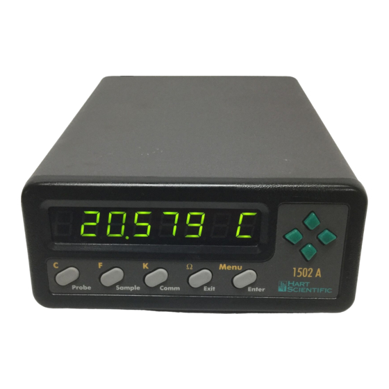
U and D— When editing a parameter, these buttons increase or decrease the value of the parameter or a selected digit. 84.981 C Ω Menu 1502 A Probe Sample Comm Exit Enter Figure 3 1502A Front Panel 1502A Manual Rev. 952801... -
Page 16: Rear Panel
IEEE-488 Port (optional) - The GPIB connector is for interfacing the thermom- eter to a computer or terminal with IEEE-488 communications. IEEE-488 – + AMERICAN FORK · UTAH 84003 12V 1.0A Made in USA POWER RS-232 PROBE Figure 4 1502A Back Panel Manual Rev. 952801 Hart Scientific... -
Page 17: General Operation
6 General Operation General Operation This section explains basic operation of the 1502A Thermometer. Selecting Units Temperature can be displayed in degrees Celsius (indicated with “C”), degrees Fahrenheit (indicated with “F”), or Kelvin (indicated with “A” for absolute). The resistance of the sensor can also be displayed (indicated with “o” for ohms). -
Page 18: Figure 5 Parameter Menu Structure
Set linefeed Factory reset LF= ON rESEt? Press briefly to skip a parameter Exit Set GPIB address Hold to exit the menu Exit Add= 22 Set GPIB EOS E= LF Figure 5 Parameter Menu Structure Manual Rev. 952801 Hart Scientific... -
Page 19: Selecting The Probe Characterization
6 General Operation Selecting the Probe Characterization Before the 1502A can measure temperature accurately it must know how to calculate temperature from the resistance of the sensor. You must select a conversion type and enter the proper characterization coefficients. There are several temperature conversion algorithms available. -
Page 20: Its-90 Prt And Coefficients
5 to 11. Parameters “A4" and ”b4" take the a4 and b4 coefficients or the a5 and b5 coefficients on the certificate. Any ITS-90 parameter of the 1502A that does not have a corresponding coefficient on the PRT’s certificate must be set to 0. -
Page 21: Table 2 Setting Coefficients Rtpw, A5, And B5
Example 1: A PRT was calibrated to ITS-90 and its calibration certificate states values for coefficients Rtpw, a4, b4, a8, and b8. Set the 1502A parameters with values from the certificate as follows. Table 3 Setting Coefficients Rtpw, a8, b8, a4, and b4... -
Page 22: Callendar-Van Dusen (Rtd) Conversion
Example 3: A PRT was calibrated to ITS-90 and its calibration certificate states values for coefficients R(273.16K), a6, b6, c6, and d. Set the 1502A parameters with val- ues from the certificate as follows: Table 4 Setting Coefficients R(273.16), a6, b6, c6, and d... -
Page 23: Setting The Characterization Coefficients
6.4.5.2 Testing the Coefficients The 1502A provides a convenient method for testing the coefficients you have entered to make sure they have been entered correctly. This is done by calcu- lating temperature for given resistances and comparing the results with tem- peratures listed on the probe’s calibration report. -
Page 24: Setting The Current
While the display is blanked a small illuminated dot appears on the left side of the display as an indication that the 1502A is still operating. Pressing any but- ton on the front panel restores the display. You can program the power saver to activate after a specified period of time from 5 minutes to 60 minutes in in- tervals of 5 minutes. -
Page 25: Digital Communications Interface
The 1502A is equipped with an RS-232 serial port. The RS-232 interface is useful for connecting the 1502A to most any microcomputer. The RS-232 socket is located on the back panel of the 1502A. Wiring of the interface cable should be as shown in Figure 6 below. -
Page 26: Setting The Baud Rate
7.1.1 Setting the Baud Rate The 1502A must be set to the same baud rate as the remote device. The baud rate of the 1502A can be set to 1200, 2400, 4800, or 9600. The default is 2400. The baud rate is set in the Comm menu. Press the Menu button (“SEt?”... -
Page 27: Duplex Mode And Linefeed
The IEEE-488 connector is located on the back panel of the 1502A above the RS-232 connector. To eliminate noise, the GPIB cable should be shielded. -
Page 28: Setting The Address
The IEEE-488 bus requires that each device has a unique address. The de- fault address of the 1502A is 22 but can be changed if necessary. The IEEE-488 address of the 1502A is set within the Comm menu after the serial linefeed parameter. -
Page 29: Table 5 Command List
[or set] IPTS-68 scale conversion CO=<value> test resistance to temperature conversion Sample Parameter Commands FI[=<value>] read [or set] filter time constant CU[=<value>] read [or set] probe current PS[=<value.] read [or set] the power saver period 1502A Manual Rev. 952801... -
Page 30: Reading Temperature
The following SCPI compatible command can also be used to return the most recent measurement but without the label and unit. FETC?<EOS> or FETCH?<EOS> returns the value of the most recent measurement Manual Rev. 952801 Hart Scientific... -
Page 31: Automatically Transmitting Measurements
7 Digital Communications Interface 7.3.1.2 Automatically Transmitting Measurements By setting the sample period, the 1502A can be programmed to automatically transmit measurements from the RS-232 port at specified intervals. The sam- ple period can be set remotely using the commands: SA=[[hh:]mm:]ss<EOS>... -
Page 32: Testing The Characterization
The following command can be used to test the probe characterization: CO=<value><EOS> returns a temperature calculated from resistance The 1502A will respond with a temperature value computed from the given re- sistance value. The temperature is given in the currently selected unit. As an... -
Page 33: Setting The Power Saver
When the RS-232 duplex mode is set to FULL all commands received by the 1502A from the RS-232 port are echoed back. Setting the mode to HALF dis- ables the echo. The duplex mode can be set remotely using the commands: DU=F<EOS>... -
Page 34: Setting The Calibration Coefficients
The instrument calibration coefficients are used to maintain the resistance measurement accuracy of the 1502A. These coefficients must not be changed except by a qualified technician during the calibration of the 1502A. The fol- lowing commands can be used to set the instrument calibration coefficients: *C0=<value><EOS>... -
Page 35: Calibration Procedure
8 Calibration Procedure Calibration Procedure The 1502A uses a three-point calibration scheme with a quadratic polynomial correction function to maintain the accuracy of its resistance measurement. The three calibration points are at 0Ω, 100Ω, and 400Ω. Three calibration pa- rameters determine the correction function: CAL0, CAL100, and CAL400. The CAL0 parameter sets the correction at 0Ω... -
Page 36: Calibration Procedure
399.991Ω, the CAL400 parameter should be ad- justed by adding 0.009 to it. Verify the accuracy at 0Ω, 25Ω , 100Ω, 200Ω, and 400Ω. The accuracy should be within the short-term accuracy limits given in the specifications. Manual Rev. 952801 Hart Scientific... -
Page 37: Maintenance
Before using any cleaning or decontamination method except those rec- • ommended by Hart, users should check with Hart Scientific Customer Ser- vice to be sure that the proposed method will not damage the equipment. If the instrument is used in a manner not in accordance with the equipment •... - Page 38 The selected conversion type is incorrect. Check to make sure the cor- • rect conversion type (ITS-90, RTD, or IPTS-68) is selected. The measurement is out of range. The 1502A may not be able to calcu- • late temperature accurately if the resistance is outside the valid range. The measured resistance may be too low or too high if the actual temperature is too low or too high or if there is a problem with the sensor (see below).
-
Page 39: 10 Troubleshooting
Cycling the power off and back on again may allow the 1502A to resume normal oper- ation. Another might be if the AC source voltage is incorrect, e.g. using 115 V when the 1502A is configured for 230 V.
Need help?
Do you have a question about the 1502A and is the answer not in the manual?
Questions and answers