Table of Contents
Advertisement
Installation Instructions
Model DAC-NET
Digital Audio Card - NETWORK (500-035100 / S24235-B3-A5)
INTRODUCTION
Features
A24205-A334-B839 (Edition 14)
P/N 315-035100-14
The Model DAC-NET from Siemens Industry, Inc. is
the CAN-BUS master for all CAN modules. One DAC-
NET is required in each control panel and each
transponder. It is the source point for eight digital
audio channels and communicates audio data via ASI-
BUS to all digital audio cards.
There is one BACnet (Building Automation & Control
Network) interface. It communicates all instructions
and messages directly with the PMI/PMI-2/PMI-3
(CPC-DAC interface).
It provides network communication (D-NET) between
control panels and transponders (nodes). The
network can be wired either Class B or Class X. Each
DAC-NET occupies one D-NET address. The DAC-
NET contains various on board tones and audio
messages.
The DAC-NET can contain an optional LPB (Local
Page Board) which has to be mounted piggyback.
This CAN module has a fixed CAN address (100) and
provides two inputs. One is for the microphone
located at the LVM and the other connects the
internal telephone system. Additionally, the LPB
provides one output for the monitor speaker located
at the LVM. For more information refer to the LPB
Installation Instructions, P/N 315-035200 /
A24205-A334-B836.
The D-NET is supervised for open, short and ground
fault. Each D-NET input / output is electrically
isolated. Wiring can be either Class B or Class X with
unshielded twisted pair. The maximum distance
between two DAC-NETs is 300m with cat3 cable,
900m with cat5 cable or 700m with cable 1pr.
18B FPLR / 1pr. 16B FPLR / 1pr. 14B FPLR. A
maximum wiring length can be up to 10 km
throughout the entire network with a maximum of
32 DAC-NET nodes. Up to 99 CAN sub-modules
are addressable. The system is able to handle
eight independent audio channels. Software updates for µC and D-NET
controller are downloadable. Tones and audio messages are downloadable.
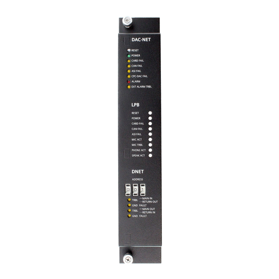
Diagnostic LEDs for troubleshooting are located on the front panel of the
DAC-NET. Refer to Figure 1.
1
+
+
+
Figure 1
DAC-NET Digital Audio Card -
NETWORK
s
Advertisement
Table of Contents

Summary of Contents for Siemens DAC-NET
-
Page 1: Installation Instructions
Model DAC-NET Digital Audio Card - NETWORK (500-035100 / S24235-B3-A5) INTRODUCTION The Model DAC-NET from Siemens Industry, Inc. is the CAN-BUS master for all CAN modules. One DAC- NET is required in each control panel and each transponder. It is the source point for eight digital audio channels and communicates audio data via ASI- BUS to all digital audio cards. -
Page 2: Operation
CC-5/CC-2 contains the signals to the CPC-DAC interface. The connection from the PMI/PMI-2/PMI-3 to the CC-5/CC-2, in which the DAC-NET is mounted, must be on the left side of the CC-5/CC-2. D-NET The D-NET Main In / Return Out and Main Out / Return In are isolated from each other and from the DAC-NET. - Page 3 The front panel of the DAC-NET contains one reset switch and seven LEDs for the DAC-NET, and one D-NET address switch and four LEDs for the D- NET. For the optionally mounted LPB, there is one reset switch and eight LEDs as shown in Figure 1.
- Page 4 PMI/PMI- 2/PMI-3 and DAC-NET has terminated. ALARM (Red) Normally OFF. When illuminated, indicates that the DAC-NET has detected an active alarm. EXT ALARM TRBL (Yellow) Normally OFF. When illuminated, indicates that the DAC-NET has detected a trouble on the External Alarm input (open circuit or short circuit).
-
Page 5: Pre-Installation
(Refer to Figure 1 for the location of the switch.) The address at the DAC-NET front panel must be the same as the address selected in the Zeus Programming Tool. To increment each digit of the address, press the “+”... - Page 6 WIRING Remove ELECTRICAL POWER prior to working on equipment. All field wiring of the DAC-NET is connected to the terminal blocks of the CC-5/CC-2 card cage slot in which it is installed. NOTE: In Canada, ULC S524 requires that all interconnecting data communications links for networks be wired DCLC (Class X) except for dedicated network communication to annunciators.
- Page 7 AIC, ZAC-40, ZAM-180, XDMC). The ASI-Bus consists of 4 pairs (Part of CC- 5). They require four 120 Ohm termination resistors on both ends. Use an ASI terminator at 60-pin connectors to fulfill it. They are shipped with DAC-NET. See Figures 9-14. The PMI/PMI-2/PMI-3 provides ASI termination at one end when used.
- Page 8 If there is a FMT install a further Analog Audio cable into the second 10-pin connector of the LVM and the other end into the FMT. The DAC-NET must be installed into any open slot of the CC-5/CC-2 which is connected at the left side with the PMI/PMI-2/PMI-3.
- Page 9 LCM-8 SCM-8 SCM-8 SCM-8 ***) FMT TERMINATION RESISTOR C24235-A1-K18 *) shipped with the DAC-NET 11 12 ASI termination resistors are inside the PMI/PMI-2/PMI-3 A separate ASI terminator is not required ***) shipped with the FMT 11 12 PSC-12 RESET POWER...
- Page 10 P/N 110-134215 C24235-A1-K2 ASI TERMINATOR C24235-A1-K1 SHIPPED WITH THE DAC-NET Figure 10 Remote Control Panel with SIM-16 and OCM-16 SIM-16 and OCM-16 have EMC-Protection for CAN Bus and 24V onboard and can be placed remote without using RNI. SCM, LCM and FCM which have no EMC-Protection can be connected to OCM-16 or SIM-16.
- Page 11 RNI is needed for EMC Protection if LVM, and FMT (SCM, LCM and FCM) shall be placed remote. Figure 11 Remote Control Panel with RNI DETAIL A NOT SUPERVISED SUPERVISED CLASS B (ULC DCLB) CAN - PSC-12 CAN + SPEAKER - SPEAKER + MIC - MIC +...
- Page 12 Figure 13 Multiple Remote Control Panels A24205-A334-B839 (Edition 14) P/N 315-035100-14...
- Page 13 DETAIL A CAN - CAN + CAN - PSC-12 CAN + SPEAKER - SPEAKER + MIC - MIC + NOT SUPERVISED HNET SUPERVISED CLASS B Class B Class X ULC DCLB SUPERVISED CLASS B CAN - CAN + SPEAKER - SPEAKER + MIC - MIC +...
-
Page 14: Electrical Ratings
ACCESSORY PACK (shipped with DAC-NET) Item Part No. Part No. SBT Munich SBT Florham Park 2 CAN Terminators C24235-A1-K2 P/N 110-134215 2 ASI Terminator C24235-A1-K1 Not Available 1 Can Termination Resistor C24235-A1-K12 P/N 140-034723 120 Ohms 1 External Alarm EOL Resistor... -
Page 15: Installation
96-pin DIN connectors and can occupy any slot in the cardcage. Figure 15 Installing the DAC-NET Insert the DAC-NET card into the card guides right side up (lettering on the front panel is legible) Slide the card in until the card edge connectors contact the receptacles on the motherboard. - Page 16 Cyber security disclaimer Siemens products and solutions provide security functions to ensure the secure operation of building comfort, fire safety, security management and physical security systems. The security functions on these products and solutions are important components of a comprehensive security concept.