
Related Manuals for GESTRA NRS 2-50


Summary of Contents for GESTRA NRS 2-50
- Page 1 Level Switch NRS 2-50 NRS 2-51 Original Installation Instructions 819179-03 E n g l i s h...
-
Page 2: Table Of Contents
Key .................................8 Installation in control cabinet ........................8 Name plate / marking ..........................9 In control cabinet: Wiring level switch Wiring diagram for level switch NRS 2-50 .....................10 Key ...............................10 Wiring diagram for level switch NRS 2-51 .....................11 Key ...............................11 Connecting supply voltage ........................12 Connecting output contacts ........................12... - Page 3 Contents - continued - Page Factory settings ..........................13 Changing factory settings Changing function and input for level electrode/transmitter ..............14 Operating the level switch Key to codes on seven-segment display ....................16 Establishing measuring range ......................17 Commissioning procedure Setting parameters..........................18 Setting the measuring range .........................19 Operation, alarm and test Indicators ..............................20 Level controller NRR 2-50 Displays ....................21...
-
Page 4: Important Notes
LED display. In the event of a malfunction a MIN and MAX alarm will be triggered. If errors occur only in the level switch NRS 2-50 / NRS 2-51, a MIN and MAX alarm is raised and the system is restarted. -
Page 5: Directives And Standards
Directives and Standards VdTÜV Bulletin “Wasserstand 100” (= Water Level 100) The level switch NRS 2-50 / NRS 2-51 in conjunction with level electrode NRG 2.-.. and level transmit- ter NRGT 26-1.. is type approved to VdTÜV Bulletin “Water Level 100”. -
Page 6: Technical Data
12 VDC Outputs NRS 2-50, NRS 2-51: 2 volt-free change-over contacts, 8 A 250 V AC / 30 V DC cos ϕ = 1. De-energizing delay: 3 sec. (MIN / MAX alarm, switchpoint adjustable). NRS 2-51: 1 volt-free change-over contact, 8 A 250 V AC / 30 V DC cos ϕ = 1. -
Page 7: Scope Of Supply
UL/cUL (CSA) Approval UL 508 and CSA C22.2 No. 14-13, Standards for Industrial Control Equipment. File E243189. Scope of supply NRS 2-50 1 Level switch NRS 2-50 1 Installation manual NRS 2-51 1 Level switch NRS 2-51 1 Installation manual... -
Page 8: In Control Cabinet: Mounting Level Switch
Housing Lower terminal strip Supporting rail type TH 35, EN 60715 Installation in control cabinet The level switch NRS 2-50, NRS 2-51 is clipped onto the support rail type TH 35, EN 60715 in the control cabinet. Fig. 1 4... -
Page 9: Name Plate / Marking
In control cabinet: Mounting level switch - continued - Name plate / marking Name plate NRS 2-50 (top) Name plate NRS 2-51 (top) Safety note Type Manufacturer designation Protection External fuse for output contacts Ambient temperature Output contacts Name plate (at the bottom) -
Page 10: In Control Cabinet: Wiring Level Switch
In control cabinet: Wiring level switch Wiring diagram for level switch NRS 2-50 NRS 2-50 M 0.5 A M 0.5 A (semi- (semi- delay) delay) Fig. 3 Connection of supply voltage 24 V DC with fuse 0.5 A (semi-delay) provided on site Level electrode NRG 21-..;... -
Page 11: Wiring Diagram For Level Switch Nrs 2-51
In control cabinet: Wiring level switch - continued - Wiring diagram for level switch NRS 2-51 NRS 2-51 M 0.5 A M 0.5 A (semi- (semi- delay) delay) Fig. 4 Connection of supply voltage 24 V DC with fuse 0.5 A (semi-delay) provided on site Level electrode NRG 21-..;... -
Page 12: Connecting Supply Voltage
In control cabinet: Wiring level switch - continued - Connecting supply voltage The equipment is supplied with 24 V DC and fused with an external semi-delay fuse 0.5 A. Please use a safety power supply unit with safe electrical isolation. The power supply unit must be electrically isolated from dangerous contact voltages and must meet at least the requirements on double or reinforced isolation according to one of the following standards: DIN EN 50178, DIN EN 61010-1, DIN EN 60730-1 or DIN EN 60950. -
Page 13: In The Plant: Wiring Level Electrode / Level Transmitter
In the plant: Wiring level electrode / level transmitter Connecting level electrode, level transmitter The level switch NRS 2-50 / NRS 2-51 is designed to be used with level electrodes NRG 21-.. and NRG 26-21 as well as the level transmitter NRGT 26-1... -
Page 14: Changing Factory Settings
Changing factory settings Danger The upper terminal strip of the equipment is live during operation. This presents the danger of electric shock! Always cut off power supply to the equipment before mounting, removing or connecting the terminal strips! Changing function and input for level electrode/transmitter The input and the function are determined by the code switch setting. - Page 15 If you want to change the input or the function, set the switches S2 to S3 of the code switch indicated in the following table Fig. 5. Code switch c Toggle switch, white Level switch NRS 2-50 Input for connecting level electrode NRG 21-.. or NRG 26-21 Input for connecting level transmitter NRGT 26-1..
-
Page 16: Operating The Level Switch
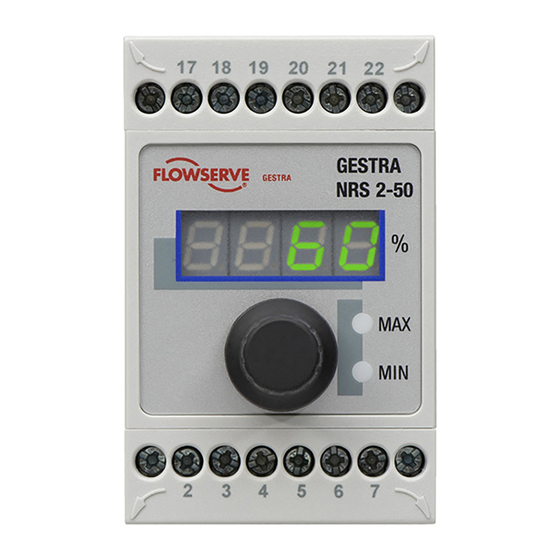
Operating the level switch Key to codes on seven-segment display Seven- OO75 OO75 segment display MAX LED LED “Pump” amber MIN LED Rotary button with integrated push-button Fig. 6 Code Description Indicated when rotary button is turned to the right: AL.Hi Alarm High MAX switchpoint... -
Page 17: Establishing Measuring Range
Operating level switch - continued - Establishing measuring range Lower end of measuring range, adjustable NRG 2.-.. Upper end of measuring range, adjustable NRGT 26-1.. Measuring range [mm] = xxx % Inactive range Max. length of installation 238 °C Adjust the lower and upper end of the measuring range for level control. -
Page 18: Commissioning Procedure
Commissioning procedure Setting parameters Seven- OO75 OO75 segment display MAX LED LED “Pump” amber MIN LED Rotary button with integrated push-button Fig. 6 Start Activity Display Function Seven-segment display shows equipment and software System test, takes approx. 3 sec. Switch on supply voltage. version. -
Page 19: Setting The Measuring Range
Commissioning - continued - Setting the measuring range Level electrode NRG 2.-.. only : Setting the measuring range, option 1 Action Display Function Reduce water level until start of measuring range A. After a short time, a hexadecimal number Calibrate start Select parameter CAL.L. -
Page 20: Operation, Alarm And Test
Operation, alarm and test Setting switchpoints, indicators Seven- OO75 OO75 segment display MAX LED LED “Pump” amber MIN LED Rotary button with integrated push-button Fig. 6 Setting the MIN/MAX switchpoints Select parameter AL.Lo, enter and save the desired MIN switchpoint setting between 0-100 % percentage. -
Page 21: Level Controller Nrr 2-50 Displays
Operation, Alarm and Test - continued - Indicators - continued - Level switch NRS 2-51 only: Fill control Level below switchpoint “Pump Pump LED illuminated amber. Pump output contact 19/20 closed. ON” Level above switchpoint “Pump Pump LED is not illuminated. Pump output contact 19/20 open. -
Page 22: Troubleshooting
Troubleshooting Indication, diagnosis and remedy Attention Before carrying out the fault diagnosis please check: Supply voltage: Is the equipment supplied with the mains voltage specified on the name plate? Wiring: Is the wiring in accordance with the wiring diagram? Faults indicated by the seven-segment display Error code Error Remedy... -
Page 23: Further Notes
Further Notes Action against high frequency interference High-frequency interference can be caused by out-of-phase switching operations. Should sporadic failures or malfunctions occur take the following remedial actions in order to suppress interference: Provide inductive loads with RC combinations according to manufacturer's specification to ensure interference suppression. - Page 24 Agencies all over the world: www.gestra.de GESTRA AG Münchener Straße 77 28215 Bremen Germany Telefon +49 421 3503-0 Telefax +49 421 3503-393 E-mail info@de.gestra.com www.gestra.de 819179-03/04-2017cm (808861-03) · GESTRA AG · Bremen · Printed in Germany...
Need help?
Do you have a question about the NRS 2-50 and is the answer not in the manual?
Questions and answers