Table of Contents
Advertisement
Repair
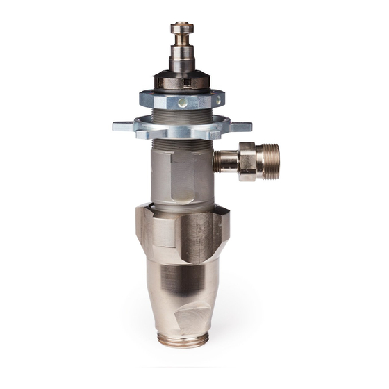
ProConnect Endurance
Displacement Pump
For professional use only.
Models: 17C487, 17C488, 17C489, 17C721, 17M992, 24Z731
Important Safety Instructions
Read all warnings and instructions in this manual and related manuals.
Be familiar with the controls and the proper usage of the equipment.
Save these instructions.
Use only genuine Graco replacement parts.
The use of non-Graco replacement parts may void warranty.
334599F
EN
ti24850b
Advertisement
Table of Contents

Related Manuals for Graco 17C487


Summary of Contents for Graco 17C487
- Page 1 Read all warnings and instructions in this manual and related manuals. Be familiar with the controls and the proper usage of the equipment. Save these instructions. ti24850b Use only genuine Graco replacement parts. The use of non-Graco replacement parts may void warranty.
-
Page 2: Table Of Contents
Technical Specifications ........19 Graco Standard Warranty ........22 Graco Information . -
Page 3: Warnings
Use Graco conductive or grounded high-pressure airless paint sprayer hoses. •... - Page 4 • Check hoses and parts for signs of damage. Replace any damaged hoses or parts. • This system is capable of producing 3300 psi. Use Graco replacement parts or accessories that are rated a minimum of 3300 psi. • Always engage the trigger lock when not spraying. Verify the trigger lock is functioning properly.
-
Page 5: Pressure Relief
Pressure Relief Pressure Relief Pressure Relief Procedure Trigger Lock Always engage the trigger lock when sprayer is stopped to prevent the gun from being triggered accidentally by hand or if dropped or bumped. This equipment stays pressurized until pressure is manually relieved. To help prevent serious injury from pressurized fluid, such as skin injection, splashed fluid and moving parts, follow the Pressure... - Page 6 Pressure Relief Turn the ON/OFF switch to OFF posi- Turn pressure control to the lowest set- tion. Wait 7 seconds for power to dissi- ting. Disengage trigger lock. pate. ti24852a Unplug power cord or shut engine off. For LineLazer ES 1000, unplug power cord and disconnect battery.
- Page 7 Pressure Relief Hold a metal part of the gun firmly to a Open any fluid drain valves in system. grounded metal pail. Trigger the gun to Leave drain valves open until ready to relieve pressure. spray again. ti24608a ti24585a Engage the trigger lock. ti24855a LineLazer ES 1000 334599F...
-
Page 8: Pump Removal
Pump Removal Pump Removal Pump removal includes disconnecting the Disconnect outlet hose and suction fluid inlet and outlet and removing the pump. hose from pump. Use a hammer to loosen pump retaining nut. ti27251a Slide pump out of the drive housing. ti27248a Turn pump retaining nut to free pump rod cover. -
Page 9: Repair
Repair Repair Dissemble Pump Dissemble intake valve. Clean and inspect. O-ring may require a pick for removal. Remove packing nut and throat adjustment spacer. Retaining nuts are NOTICE not removable and not sold separately. If using a pick to remove the O-ring use care to avoid damage to the machined surfaces. - Page 10 Repair Tap piston rod out of cylinder with a Clean and inspect parts. (The piston hammer or flip over and tap piston rod has a special thread locking/sealing out against a bench. patch. Apply thread sealant to the threads. ti24875a Do not clean or wipe the piston valve threads.
-
Page 11: Assemble Pump
Repair Assemble Pump Remove and discard throat packing and glands from the cylinder. Soak leather packings in SAE 30W oil for one hour before assembly. Leather Packings ti24890a Leather Packings ti24880a ti24893a 334599F... - Page 12 Repair Install ball in piston rod. If thread seal- Assemble leather throat packings ant is applied to piston valve threads, soaked earlier. ensure that none gets on the ball. Leather Packings ti24893a ti24891a Loosely install packing nut with o-ring onto cylinder. Torque to 27 ±...
- Page 13 Repair Apply liberal amounts of grease or oil to Grease o-ring and place on outside piston packings. diameter ring groove. ti24897a Clean seat thoroughly. Reassemble ti24895a intake valve with a seat, ball, and new o-ring. Seat may be flipped over and used on other side.
- Page 14 Repair 10. Torque to 100 ± 5 ft-lb (136 ± 7 N•m). 11. Install o-ring onto packing nut. Torque to 75 ± 5 in-lb (8.5 ± 0.5 N•m) or addi- tional 1/2 turn from hand tight. ti24899a ti24900a 334599F...
- Page 15 Repair Throat Packing Adjustment 12. Storage This equipment stays pressurized until pressure is manually relieved. To help prevent serious injury from pressurized fluid, such as skin injection, splashed fluid and moving parts, follow the Pressure Relief Procedure whenever sprayer is stopped and before sprayer is cleaned or checked, and before equipment is serviced.
-
Page 16: Parts
Parts Parts ti24903a 334599F... -
Page 17: Parts List
209* 180073 GLAND, female, piston V-Max 211* 15G234 GUIDE, piston UHMWPE, blue 239937 VALVE, piston (included with 201) Models 17C487, 17C488, 17C489, 17C721 213 15C011 GUIDE, ball 17C231 FITTING, pump, QD, 215 246429 KIT, seat, carbide 1/4 npt includes 213, 217 and... -
Page 18: Pump Installation
Pump Installation Pump Installation Pump installation includes securing the pump and connecting to the fluid inlet and outlet. Connect outlet hose to pump. ti24087a Use both hands to tighten pump retain- ti24086a ing nut. Move pump displacement rod up or down until it slides into the connecting rod when the pump is slid into the drive housing. -
Page 19: Technical Specifications
Technical Specifications Technical Specifications PC Displacement Pump Metric Maximum fluid working pressure. 3300 psi 228 bar, 22.8 MPa Inlet/Outlet Sizes Fluid inlet size 1.0 in. diameter Fluid outlet size 1/4 in. Wetted materials on all models stainless steel, PTFE, leather, nylon, zinc-plated and nickel-plated carbon steel, tungsten carbide, chrome plating, UHMWPE, acetal, polyethylene, nylon 334599F... - Page 20 Notes Notes 334599F...
- Page 21 Notes Notes 334599F...
-
Page 22: Graco Standard Warranty
Graco’s written recommendations. This warranty does not cover, and Graco shall not be liable for general wear and tear, or any malfunction, damage or wear caused by faulty installation, misapplication, abrasion, corrosion, inadequate or improper maintenance, negligence, accident, tampering, or substitution of non-Graco component parts. -
Page 23: Graco Information
Graco Information Graco Information For the latest information about Graco products, visit www.graco.com. For patent information, see www.graco.com/patents. TO PLACE AN ORDER, contact your Graco distributor or call 1-800-690-2894 to identify the nearest distributor. 334599F... - Page 24 Original instructions. This manual contains English. MM 334599 Graco Headquarters: Minneapolis International Offices: Belgium, China, Japan, Korea GRACO INC. AND SUBSIDIARIES • P.O. BOX 1441 • MINNEAPOLIS MN 55440-1441 • USA Copyright 2014, Graco Inc. All Graco manufacturing locations are registered to ISO 9001. www.graco.com...
Need help?
Do you have a question about the 17C487 and is the answer not in the manual?
Questions and answers