Table of Contents
Advertisement
Advertisement
Table of Contents

Summary of Contents for ESIT ECI
- Page 2 ECI Multi Functional Weighing Controller Operating Manual Esit Technical Support Esit Support Line for Turkey 0533 732 15 74 Email: servis@esit.com.tr Istanbul Phone: Direct Line 0216 585 18 88 / 0216 585 18 18 Extension: 141 /142 0216 585 18 89...
- Page 3 ECI Multi Functional Weighing Controller Operating Manual Page 3...
-
Page 4: Considerations
ECI Multi Functional Weighing Controller Operating Manual 1 Considerations • Do not power-up the device before making sure that the device connections are made according to this manual. • Do not open the case or disconnect-insert the connections before disconnecting the device from the power source. -
Page 5: Table Of Contents
ECI Multi Functional Weighing Controller Operating Manual Table of Contents 1 Considerations ................................4 2 Introduction ................................15 3 Physical Dimensions ..............................17 4 Specifications................................19 4.1 Technical Specifications ............................ 19 4.2 Use Properties..............................20 5 Installation and Connections ............................ 22 5.1 Standard Modules ............................. -
Page 6: Table Of Contents
ECI Multi Functional Weighing Controller Operating Manual 6.1.2 Symbols ..............................33 6.1.3 Keys................................35 6.2 Menu Screen ..............................36 6.2.1 Screen Layout ............................. 36 6.2.2 Symbols ..............................37 6.2.3 Keys................................38 6.3 Change Parameter Screen (Numeric or Alpha-Numeric Entry Type) ..............39 6.3.1 Screen Layout ............................. -
Page 7: Table Of Contents
ECI Multi Functional Weighing Controller Operating Manual 6.5 Ordered Menu Screen ............................44 6.5.1 Screen Layout ............................. 44 6.5.2 Symbols ..............................45 6.5.3 Keys................................46 6.6 Confirmation Screen ............................47 6.6.1 Screen Layout ............................. 47 6.6.2 Symbols ..............................48 6.6.3 Keys................................48 6.7 Message Screen ............................... -
Page 8: Table Of Contents
ECI Multi Functional Weighing Controller Operating Manual 7.1.2 Program Selection Screen .......................... 54 7.2 Menu List................................55 7.3 Using the Menu ..............................56 7.3.1 Terminal Menu ............................56 7.3.2 Weighing Menu ............................85 7.3.3 Optional Communication Menu ......................... 104 7.3.4 Optional In/Out Menu ..........................116 7.3.5 Optional In/Out Menu .......................... -
Page 9: Table Of Contents
ECI Multi Functional Weighing Controller Operating Manual 8.2 mV/V Calibration ............................. 146 8.3 Coefficient Calibration ............................. 150 8.4 Zero Calibration ............................... 153 9 Software Update ..............................157 10 Annex 1: Optional Modules ..........................162 10.1 Slot3 (Optional Communication Slot) : ......................162 10.1.1 E-MDL-COM (Serial Communication Module): .................. -
Page 10: Table Of Contents
ECI Multi Functional Weighing Controller Operating Manual 10.4.2 E-MDL-EXP (Relay Expansion Module) ....................175 11 Annex 2: Batching Program ..........................180 11.1 System Operation ............................180 11.2 Batching Program Screen ..........................182 11.2.1 Screen Layout ............................183 11.2.2 Keys ................................ 185 11.3 Batching Program Status Messages ...................... -
Page 11: Table Of Contents
ECI Multi Functional Weighing Controller Operating Manual 12 Annex 3: Filling Program ............................217 12.1 Filling Program Features ..........................217 12.2 System Operation ............................218 12.2.1 Bag Filling: .............................. 219 12.2.2 Scale Filling: ............................220 12.3 Main Screen Overview ..........................221 12.3.1 Screen Layout ............................ -
Page 12: Table Of Contents
ECI Multi Functional Weighing Controller Operating Manual 12.7.3 Identifying the Filling System to the Device ..................... 251 13 Annex 4: Batching Configurator ........................... 259 14 Annex 5 Modbus Usage ............................266 14.1 Device Menu Settings ............................ 266 14.2 Connection Point Settings ..........................266 14.3 Modbus Commands ............................ -
Page 13: Table Of Contents
ECI Multi Functional Weighing Controller Operating Manual 14.5.4 Writing to EEPROM section ........................278 14.6 Command Register Functions ........................279 14.6.1 Taring ..............................281 14.6.2 Selecting Recipe ............................. 281 14.6.3 Start Batching ............................282 14.6.4 Stop Batching............................282 14.6.5 Setting the Relay 1 Minimum Value......................283 14.6.6 Setting the Relay 2 Maximum Value ...................... - Page 14 ECI Multi Functional Weighing Controller Operating Manual 16.2 Batching Program ............................292 16.3 Filling Program .............................. 293 17 Error, Warning and Information Messages ......................295 Page 14...
-
Page 15: Introduction
2 Introduction ECI is a smart signal converter and control device which is designed for weigh measuring systems. It is a fast, sensitive device with a high accuracy class. It is designed suitably for using at industrial applications and standard weigh measuring areas. - Page 16 ECI Multi Functional Weighing Controller Operating Manual Page 16...
-
Page 17: Physical Dimensions
ECI Multi Functional Weighing Controller Operating Manual 3 Physical Dimensions Standard Model Weight 360 g Page 17... - Page 18 ECI Multi Functional Weighing Controller Operating Manual Page 18...
-
Page 19: Specifications
ECI Multi Functional Weighing Controller Operating Manual 4 Specifications 4.1 Technical Specifications Model ECI, E Series Load Cell Input +/- 2.50–160mV/V A/D Speed (/second) 1600 Screen Resolution 6 digit (1/1.000.000) Supply 12-24V DC Display LCD (101x33 pixel graphic, 4.5 inch) -
Page 20: Use Properties
ECI Multi Functional Weighing Controller Operating Manual 4.2 Use Properties • Multi-language support • 5 touch keys • Plain use and setting thanks to the indexed menu system structure • Internal batching and filling program • Smart “plug and play” expansion structure •... - Page 21 ECI Multi Functional Weighing Controller Operating Manual Page 21...
-
Page 22: Installation And Connections
ECI Multi Functional Weighing Controller Operating Manual 5 Installation and Connections The number of each slot is shown as follows on the back cover of the ECI device Slot Numbers Slot6 Slot5 Slot4 Slot3 Slot2 Slot1 Page 22... - Page 23 ECI Multi Functional Weighing Controller Operating Manual • Slot1: Used for the Terminal (Supply & Communication) Module. Following module(s) can be used; E-ECI-PWR (Standard) module can be inserted. • Slot2: Used for Weighing (Load Cell) Module. Following module(s) can be used;...
-
Page 24: Standard Modules
ECI Multi Functional Weighing Controller Operating Manual 5.1 Standard Modules Standard modules are the units that are given in the base mode with the ECI E series devices. Respective modules and explanations are given below. Terminal Module Weighing Module Page 24... -
Page 25: Slot1: Terminal (Supply And Communication Module)
ECI Multi Functional Weighing Controller Operating Manual 5.1.1 Slot1: Terminal (Supply and Communication Module) RS232 Remote Display Connection Supply Connection Page 25... - Page 26 ECI Multi Functional Weighing Controller Operating Manual 5.1.1.1 Supply Connection 5.1.1.2 Communication Connections Note: When the “R.Display” output is used with Esit brand Remote displays, red and White cables of the Display must be short circuited Page 26...
- Page 27 ECI Multi Functional Weighing Controller Operating Manual 5.1.1.3 Printer Connection ECI, supports EPM203-MRS model printer. Printer connection must be as follows. Page 27...
-
Page 28: Slot2: Weighing (Load Cell) Module
ECI Multi Functional Weighing Controller Operating Manual 5.1.2 Slot2: Weighing (Load Cell) Module 5.1.2.1 Esit Load Cell Connection Page 28... - Page 29 ECI Multi Functional Weighing Controller Operating Manual 5.1.2.2 Six (6) Cable Load Cell Connection Sense + Esit Colours Sense + Blue Sense - Sense - Orange Out + White Out + Out - Out - Supply + Green Supply -...
- Page 30 ECI Multi Functional Weighing Controller Operating Manual 5.1.2.3 Four (4) Cable Load Cell Connection Esit Colours Sense - Green Sense - Black Out + Out + White Out - Out - Supply + Green Supply - Black Supply + Sense-terminal is short Supply - circuit with Supply –...
- Page 31 ECI Multi Functional Weighing Controller Operating Manual Page 31...
-
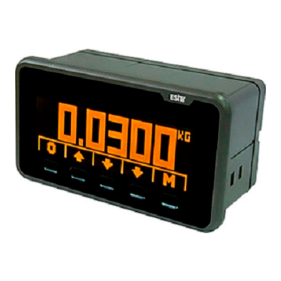
Page 32: Screenshots
ECI Multi Functional Weighing Controller Operating Manual 6 Screenshots 6.1 Weighing Main Screen Main screen shot will be as shown at side The screen will be displayed as shown at side when the tare is removed Page 32... -
Page 33: Screen Layout
ECI Multi Functional Weighing Controller Operating Manual 6.1.1 Screen Layout Weighing Indicator Keys Weighing Range Mobility Zero Indicator Tare Status Unit 6.1.2 Symbols Indicates current weighing range. It is displayed when the measuring type is Weighing selected as “Multi Partition” or “Multi Range”. E1: Lower Zone, E2: Upper Zone Range and E3 represents the final zone. - Page 34 ECI Multi Functional Weighing Controller Operating Manual Page 34...
-
Page 35: Keys
ECI Multi Functional Weighing Controller Operating Manual 6.1.3 Keys Reset Key Used for resetting the display. Tare Key Used for taking the weight on the load cell as tare. Tare Clean Key Used for cancelling the tare value and showing the gross value. -
Page 36: Menu Screen
ECI Multi Functional Weighing Controller Operating Manual 6.2 Menu Screen Menu screenshot is as shown at side. 6.2.1 Screen Layout Menu Logo Menu No Lock Menu Names Keys Page 36... -
Page 37: Symbols
ECI Multi Functional Weighing Controller Operating Manual 6.2.2 Symbols Menu Logo Respective menu logo. Menu No Respective menu number. Shows that a parameter has to be changed in order to Access the Software Lock menu. Shows that it is required to add or replace hardware in order to Hardware Lock Access the menu. - Page 38 ECI Multi Functional Weighing Controller Operating Manual 6.2.3 Keys Left Arrow Key Used for shifting to an upper menu on the menu screen. Up Arrow Key Used for browsing among the options on the menu screen. Down Arrow Key Used for browsing among the options on the menu screen.
-
Page 39: Change Parameter Screen (Numeric Or Alpha-Numeric Entry Type)
ECI Multi Functional Weighing Controller Operating Manual 6.3 Change Parameter Screen (Numeric or Alpha-Numeric Entry Type) The change parameter screen will be displayed as shown at side: Note: The values entred in the screen must the multiplies of the “Resolution” parameter. For example if the ”Resolution” is selected as 5 and the value entered in this screen is 101, an information message appears and the number is automatically rounded to 100 and returned to the parameter changing screen. - Page 40 ECI Multi Functional Weighing Controller Operating Manual 6.3.2 Symbols Menu No Respective menu number. Title Name of the current menu Option Value to be adjusted 6.3.3 Keys Used for returning to the menu screen from the parameter settings Exit Key.
- Page 41 ECI Multi Functional Weighing Controller Operating Manual Page 41...
-
Page 42: Change Parameter Screen (Selective Type)
ECI Multi Functional Weighing Controller Operating Manual 6.4 Change Parameter Screen (Selective Type) The selective type change parameter screen will be displayed as shown at side: 6.4.1 Screen Layout Menu No Menu Title Option No Option Arrow Keys Page 42... - Page 43 ECI Multi Functional Weighing Controller Operating Manual 6.4.2 Symbols Menu No Respective menu number. Menu Title Name of the respective parameter. Option No Number of the parameter option. Option Explanation of the respective parameter option. Shows if there is any option above or below the...
-
Page 44: Ordered Menu Screen
ECI Multi Functional Weighing Controller Operating Manual 6.5 Ordered Menu Screen Ordered menu is made for providing convenience in the menus with more than one sub-menu. For example, there are Unit, Capacity, Resolution and Measuring Type sub-menus in the Settings menu under the Weighing menu. When you enter this menu, you can change every parameter related to the weighing setting subsequently. - Page 45 ECI Multi Functional Weighing Controller Operating Manual 6.5.2 Symbols Menu No Respective menu number. Menu Title Name of the current menu. Sub-Menu Title Name of the current sub-menu. Sub-Menu No Sub-Menu number. Number of Sub- Number of Sub-Menus of the respective menu...
- Page 46 ECI Multi Functional Weighing Controller Operating Manual 6.5.3 Keys Return Key Used for returning to the previous menu in the ordered menu. Up Arrow Key Used for browsing among the options in the selection list. Down Arrow Key Used for browsing among the options in the selection list.
-
Page 47: Confirmation Screen
ECI Multi Functional Weighing Controller Operating Manual 6.6 Confirmation Screen When key is pushed after entering to menu and changing any parameter, the confirmation screen as shown at side will appear before saving the new parameter. 6.6.1 Screen Layout Screen Title... - Page 48 ECI Multi Functional Weighing Controller Operating Manual 6.6.2 Symbols Confirmation Screen Respective menu title. Title Confirmation Screen Respective menu logo. Logo Parameters Changed Name of the parameter changed Parameter Value New value of the parameter changed. 6.6.3 Keys Cancel Key Used for returning to the previous menu without saving the parameters changed.
-
Page 49: Message Screen
ECI Multi Functional Weighing Controller Operating Manual 6.7 Message Screen The message screen shown at side will display when it is necessary to inform the user.There are 3 types of message These are information, warning and error messages. 6.7.1 Screen Layout... - Page 50 ECI Multi Functional Weighing Controller Operating Manual 6.7.2 Symbols Message Screen Title Indicates the message type Respective message Message No number. The logo related to the Message Screen Logo message type. Message The message content Page 50...
- Page 51 ECI Multi Functional Weighing Controller Operating Manual Page 51...
-
Page 52: Using The Device
The device is turned on by supplying energy after making the Supply and Load Cell connections. Start-up logo and version number will be displayed on ECI LCD screen during the start-up. Then the functional test will be performed and the Optional card inserted will be recognized and tested. Lastly, the main screen will be displayed and the measuring starts. -
Page 53: Program Selection
ECI Multi Functional Weighing Controller Operating Manual 7.1 Program Selection ECI, supports more than one operating screens (programs) (such as "Weighing," Batching", "Filling" etc). Operating screen selection is made when the first energy is given to the device. After giving the first energy, when the following screenshot appears, the 1. -
Page 54: Program Selection Screen
ECI Multi Functional Weighing Controller Operating Manual The status of the outputs may change when the program is changed. Thus, the respective warning message is displayed before the program selection screen. 7.1.2 Program Selection Screen After selecting the desired program, selection is confirmed... -
Page 55: Menu List
ECI Multi Functional Weighing Controller Operating Manual 7.2 Menu List Menu List is as follows: Terminal Weighing Optional Communication Menu 1.1. Language 2.1. Security Type Optional In/Out Menu Selection 2.2. Settings Optional In/Out Menu 1.2. Date 2.3. Filter Optional Expansion Menu 1.3. -
Page 56: Using The Menu
ECI Multi Functional Weighing Controller Operating Manual 7.3 Using the Menu 7.3.1 Terminal Menu The menus related to the Terminal module inserted to slot 1 of the device are displayed under this menu. Terminal It is the main menu that contains the device settings and the settings related to Slot1. - Page 57 ECI Multi Functional Weighing Controller Operating Manual Date Date settings are made. The date data can be changed in dd.mm.yyyy format. Time Time settings are made. The time data can be changed in hh.mm format. Page 57...
- Page 58 ECI Multi Functional Weighing Controller Operating Manual Communication Serial Out Contains the terminal serial out settings. This menu is an ordered type menu. Sub-menus are Mode and Period. It functions differently in Indication, Batching and Filling programs. Explanation is made...
- Page 59 ECI Multi Functional Weighing Controller Operating Manual Page 59...
- Page 60 ECI Multi Functional Weighing Controller Operating Manual 2) Accuracy: Net weight information is sent continuously. (Baudrate is 9600bps)The format of the data string sent is same as the Speed mode 3) Detail: The weight information is sent in detail.(Baudrate is 9600bps).The format of the data string sent is as follows.
- Page 61 ECI Multi Functional Weighing Controller Operating Manual 4) Stability: Net weight information is sent 10 times when the stability is observed.(Baudrate is 9600 bps.) The format of the data string sent is same as the Speed mode. 5) Command: Functions as a query from a remote computer or similar device (Baudrate is...
- Page 62 ECI Multi Functional Weighing Controller Operating Manual For example; Command: GI0 Response: 1001->LSB(Input1) Input4 Input3 Input2 Input1 0: No Input: 1: Input exists For example; Command: GO0 Response: 3 The binary number system equivalent of the response received: 0011 Exit4...
- Page 63 ECI Multi Functional Weighing Controller Operating Manual 6) Printer: It is the printer connection option. This option is locked as it is not active under the indication program. Period Selection for RS232 serial out sending frequency. The options are; 1) 6/Min...
- Page 64 ECI Multi Functional Weighing Controller Operating Manual Batching Program Mode It is the communication type selection. The options are; 1) Speed: Net weight information is sent continuously during the batching operation. (Baudrate is 115200bps) For example; The screen value of "2148.0kg" is sent as follows.
- Page 65 ECI Multi Functional Weighing Controller Operating Manual 2) Accuracy: Net weight information is sent continuously during the batching operation. (Baudrate is 9600bps)The format of the data string sent is same as the Speed mode 3) Detail: The information is sent in detail after the batching operation is over. (Baudrate is 9600bps).The format of the data string sent is as follows.
- Page 66 ECI Multi Functional Weighing Controller Operating Manual 4) Stability: The total batching weight is sent after the batching is over.(Baudrate is 9600 bps.) The format of the data string sent is same as the Speed mode. Command: This mode is not active in batching mode.
- Page 67 ECI Multi Functional Weighing Controller Operating Manual Period Selection for RS232 serial out sending frequency. The options are; 7) 6/Min 8) 1/Sec 9) 10/Sec 10) 100/Sec 11) 400/Sec 12) 800/Sec Not: Period menu is not shown when "Command" or "Stability" modes are selected.
- Page 68 ECI Multi Functional Weighing Controller Operating Manual Filling Program Mode It is the communication type selection. The options are; 1) Speed: The filling weight is sent continuously during the filling. (Baudrate is 115200bps) For example; The screen value of "2148.0kg" is sent as follows.
- Page 69 ECI Multi Functional Weighing Controller Operating Manual 2) Accuracy: The filling weight is sent continuously during the filling. (Baudrate is 9600bps)The format of the data string sent is same as the Speed mode 3) Detail: The information is sent in detail after the filling operation is over. (Baudrate is 9600bps).The format of the data string sent is as follows.
- Page 70 ECI Multi Functional Weighing Controller Operating Manual 4) Stability: The final filling weight is sent after the filling is over.(Baudrate is 9600 bps.) The format of the data string sent is same as the Speed mode. 5) Command: This mode will be shown as locked as it is not active in filling program.
- Page 71 ECI Multi Functional Weighing Controller Operating Manual Period Selection for RS232 serial out sending frequency. The options are; 1) 6/Min 2) 1/Sec 3) 10/Sec 4) 100/Sec 5) 400/Sec 6) 800/Sec Not: Period menu is not shown when "Command" , "Stability" or "Detail modes are selected.
- Page 72 ECI Multi Functional Weighing Controller Operating Manual Remote Display(In Indication and Filling Programs) It is the section that contains the remote display out (opto-coupler) settings. This menu is an ordered type menu. Sub-menus are Mode and Baudrate. Mode The options are;...
- Page 73 ECI Multi Functional Weighing Controller Operating Manual Remote Display(In Batching Program) It is the section that contains the remote display out (opto-coupler) settings. This menu is an ordered type menu. Sub-menus are Mode and Baudrate. Mode The options are; 1) Inactive: No data transfer can be made to the remote display.
- Page 74 ECI Multi Functional Weighing Controller Operating Manual USB Recording It is the menu where the recording settings are made. This menu is an ordered type menu. Sub-menus are Mode and Period. It is active under filling and indication programs. Mode It is the recording type selection.
- Page 75 ECI Multi Functional Weighing Controller Operating Manual The format of the data recorded in indication program is as follows. USB recording mode "Weight" 169.2 USB recording mode "Detail" Tare Gross Date Time Status 169.2 Chr 9 128.5 Chr 9 297.7...
- Page 76 ECI Multi Functional Weighing Controller Operating Manual The format of the data recorded in batching program is as follows. USB recording mode "Weight" USB recording mode "Detail" Meter Date Time Total Silo1 Silo2 Chr 9 12/02/2013 Chr 9 09:52 Chr 9...
- Page 77 ECI Multi Functional Weighing Controller Operating Manual The name of the saved file is as "YearMonthDayeMode"_RecipeName format. For example; 12042013W_RECETE1 Page 77...
- Page 78 ECI Multi Functional Weighing Controller Operating Manual The format of the data recorded in filling program is as follows. USB recording mode "Weight" 1000 USB recording mode "Detail" Meter Total Tare Gross Date Time Chr 9 1000 Chr 9 Chr 9...
- Page 79 ECI Multi Functional Weighing Controller Operating Manual The name of the saved file is as "YearMonthDayeMode"_ProductName format. For example; 12042013D_Nohut Page 79...
- Page 80 ECI Multi Functional Weighing Controller Operating Manual Period It is the selection for USB Recording frequency. The options are; 1) 10/Sec 2) 1/Sec 3) 1/Min 4) 4/Hour Not: The Period menu is not displayed when "Inactivate" mode is selected Period menu is not displayed in Batching and Filling programs.
- Page 81 ECI Multi Functional Weighing Controller Operating Manual Keys It is the menu where the key settings are made. This menu is an ordered type menu. Sub-menus are "Tone" and "Sensitivity". Tone It is the key tone selection. The options are;...
- Page 82 ECI Multi Functional Weighing Controller Operating Manual Service LCDPixelTest It is the screen test menu in LCD. Pixel and rear light control is made. CPU Temperature Inside temperature of the device is displayed for 3 seconds. Memory Test It is used for understanding whether the memory is functional or not.
- Page 83 ECI Multi Functional Weighing Controller Operating Manual CommunicationTest Terminal It is used for understanding whether the communication port is functional or not. The data received from the serial port is displayed at the receiving section. "ESIT" wording is sent to the serial port at the same time.
- Page 84 ECI Multi Functional Weighing Controller Operating Manual Version No Used for displaying the device version number. FactorySettings Used for returning the device parameters to the Factory settings. Note: The device can also be returned to the factory settings by pressing to the calibration key for 10 seconds while the device is at the main screen.
-
Page 85: Weighing Menu
ECI Multi Functional Weighing Controller Operating Manual 7.3.2 Weighing Menu The menus related to the weighing module inserted to slot 2 of the device are displayed under this menu. Weighing It is the menu that contains weighing device (Slot2-Load Cell Module) parameters. - Page 86 ECI Multi Functional Weighing Controller Operating Manual Security Type Contains the weighing device security settings. The options are; 1) Commercial Use:Weighing parameters and calibration cannot be changed. (Locked) 2) CalibrationLock: Weighing parameters can be changed but the calibration cannot be changed.
- Page 87 ECI Multi Functional Weighing Controller Operating Manual Settings This menu is an ordered type menu where the weighing parameters are set forth. The sub-menus are "Unit", "Capacity", "Resolution" and "Measuring Type". Unit Determines the unit of the weighing device . The options are;...
- Page 88 ECI Multi Functional Weighing Controller Operating Manual Resolution It is the scale interval (e) selection. e: It is the smallest screen change quantity. Scale Interval Scale Interval is automatically calculated as the multiplies of 1, 2 and 5 depending on the capacity parameter and presented as a selection.
- Page 89 ECI Multi Functional Weighing Controller Operating Manual When the custom resolution is selected Multiple and Scale Interval menus appear and the product of the values selected in these menus are determined as the walking step. Multiples The options are; 1) 1000...
- Page 90 ECI Multi Functional Weighing Controller Operating Manual Measuring Type Determines the operation of the weighing device. In weighing devices; “e”: is referred as the scale interval It is the difference between two subsequent indications. There may be a signle "e" division as well as more than one partitions. The options related to this parameter are;...
- Page 91 ECI Multi Functional Weighing Controller Operating Manual Single Partition: The weighing device with a single scale interval and capacity. Multi Interval: In this operation there are 3 different scale intervals and capacities. There is a different scale interval in each capacity range;...
- Page 92 ECI Multi Functional Weighing Controller Operating Manual Multi Partition: In this operation there are 3 different scale intervals and capacities. There is a different scale interval in each capacity range; e1 (first zone scale interval): is determined with Resolution parameter...
- Page 93 ECI Multi Functional Weighing Controller Operating Manual UpperZoneLimit: It is activated when the measuring type is selected as "Multi Interval" or "Multi Partition". It is the maximum value that relates to the 2. scale interval (e2). LowerZoneLimit: It is activated when the measuring type is selected as "Multi Interval"...
- Page 94 ECI Multi Functional Weighing Controller Operating Manual Filter It is the menu where the filter settings are made. This menu is an ordered type menu. The sub-menus are "Mode", "AverageQuantity", "Speed", "Vibration" and "Stability Period". Mode It is the filter mode selection. The options are;...
- Page 95 ECI Multi Functional Weighing Controller Operating Manual Average Quantity The selection for the number data to be used for the moving average filter. The options are; 1) 8 2) 16 3) 32 Note: When gResolver mode is selected, "AverageQuantity" is not...
- Page 96 ECI Multi Functional Weighing Controller Operating Manual Stability Period The options are; 1) Short (0.5 sec): Current measurement value is monitored for 0,5 sec. 2) Medium (1.0 sec): Current measurement value is monitored for 1 sec. 3) Long (2.0 sec): Current measurement value is monitored for 2 sec.
- Page 97 ECI Multi Functional Weighing Controller Operating Manual Zero/Tare It is the menu where the zeroing and taring are made. This menu is an ordered type menu. The sub*menus are "Mode", "Zero Limit", "Starting Zero" and "Stagnancy". Mode The options are;...
- Page 98 ECI Multi Functional Weighing Controller Operating Manual Zero Limit 1) %1 Capacity: Zeroing is made if the weight value of less than 1 % of the Capacity. 2) %2 Capacity: Zeroing is made if the weight value of less than 2 % of the Capacity.
- Page 99 ECI Multi Functional Weighing Controller Operating Manual Stagnancy The options are; 1) Stab.Wait: Stagnancy( ) is necessary for taring and zeroing. If there is no stagnancy warning message is displayed on the screen. 2) Always: Taring and zeroing is made regardless of stagnancy.
- Page 100 ECI Multi Functional Weighing Controller Operating Manual Calibration It is explained in detail in Calibration section. Service Sys.Doctor System doctor interprets the values obtained from the load cell and provides detailed information on the ambient vibration, load status and drift.
- Page 101 ECI Multi Functional Weighing Controller Operating Manual A/D Count ADC internal count value is displayed on the screen. Expresses the numerical equivalent of the signal connected to the Load Cell module. Count Value varies depending on the "Load Cell Type"...
- Page 102 Module" in Slot 2. Thus, the previous weighing settings can be recovered anytime by making Back-up > Recovery operation. Furthermore the "Load Cell Module" which contains the back-up can be inserted to another ECI and the weighing setting and calibration data can be transferred to another device by making Back-up > Recovery operation.
- Page 103 ECI Multi Functional Weighing Controller Operating Manual Note: If not Back-up operation is made to the "Load Cell Module" before, then no "Recovery" operation can be made and relevant message will be displayed. Page 103...
-
Page 104: Optional Communication Menu
ECI Multi Functional Weighing Controller Operating Manual 7.3.3 Optional Communication Menu The menus related to the communication module inserted to slot 3 of the device are displayed under this menu. If there is not any communication module, this menu is displayed under the name "Empty Slot". - Page 105 ECI Multi Functional Weighing Controller Operating Manual Mode It is the communication type selection. 1) Speed: Net weight information is sent continuously. (Baudrate is 115200bps.) For example; The screen value of "2148.0kg" is sent as follows. Character ‘ ‘ ‘ ‘...
- Page 106 ECI Multi Functional Weighing Controller Operating Manual 3) Detail: Weight data is sent in detail. (Baudrate is 9600bps)The format of the data string sent is same as follows. Tare Gross Date Time Status 169.2 128.5 297.7 12/02/2013 09:52 Status E:Error...
- Page 107 ECI Multi Functional Weighing Controller Operating Manual 5) Command: Functions as a query from a remote computer or similar device (9600bps) Not case sensitive Command List: 'R': Resets the device (Reset). 'Z': Functions as reset key. 'T': Functions as taring key.
- Page 108 ECI Multi Functional Weighing Controller Operating Manual Baudrate It is the selection for RS232 serial output communication speed. The options are; 1) 1200 2) 2400 3) 4800 4) 9600 5) 19200 6) 38400 7) 57600 8) 115200 Note: Only 115200 can be selected if "Speed" Mode is selected.
- Page 109 ECI Multi Functional Weighing Controller Operating Manual Period Selection for optional module serial out transmission frequency. The options are; 1) Stable: Transmission is made when stability is observed (10Hz). 2) 6/Min: Option for transmission frequency per minute. 3) 1/Sec: Option for transmission frequency per second.
- Page 110 ECI Multi Functional Weighing Controller Operating Manual Modbus Mode It is the Modbus communication mode. The options are; 1) RTU: Each byte data to be sent is meaningful and the transmission is made by coding with CRC control byte. 2) ASCII: Each byte data to be sent is sent as two separate bytes and in coding that can be displayed as Ascii.
- Page 111 It is used for understanding whether the communication port is functional or not. The data received from the serial port is displayed at the receiving section. "ESIT" wording is sent to the serial port at the same time. Page 111...
- Page 112 ECI Multi Functional Weighing Controller Operating Manual 7.3.3.2 Optional Profibus Communication Menu Following menus will appear if Profibus module is inserted to slot 3. Profibus Module This is the menu where the parameters of the Profibus module are set forth.
- Page 113 ECI Multi Functional Weighing Controller Operating Manual 7.3.3.3 Optional Ethernet IP Communication Module Following menus will appear if Ethernet IP module is inserted to slot 3. Ethernet IP This is the menu where the parameters of the Ethernet IP module are set forth.
- Page 114 ECI Multi Functional Weighing Controller Operating Manual xx.IP.xx.xx 2. part of the IP address. Value between 1-255 can be entered. xx.xx.IP.xx 3. part of the IP address. Value between 1-255 can be entered. xx.xx.xx.IP 4. part of the IP address. Value between 1-255 can be entered.
- Page 115 ECI Multi Functional Weighing Controller Operating Manual Service The screen where the Ethernet IP communication settings are displayed. Page 115...
-
Page 116: Optional In/Out Menu
ECI Multi Functional Weighing Controller Operating Manual 7.3.4 Optional In/Out Menu The menus related to the In/Out module inserted to slot 4 of the device are displayed under this menu. If there is not any In/Out module, this menu is displayed under the name "Empty Slot". - Page 117 ECI Multi Functional Weighing Controller Operating Manual Mode It is the relay operation mode selection. The options are; 1) Inactive: The relay is not active. 2) Net Value: Operates according to the NET value. Taring affects the operation of the relay.
- Page 118 ECI Multi Functional Weighing Controller Operating Manual Minimum It is active when "Net Value" or "Gross Value" mode is selected. It is the lowest value of the weight range where the relay contact will be active. Maximum It is active when "Net Value" or "Gross Value"...
- Page 119 ECI Multi Functional Weighing Controller Operating Manual Delay Determines the period after which the relay contact will change state after the desired situation occur. Contact Type Determines the start-up positions of the relays contacts. The options are; 1) Norm.On:Relay contact is open circuit at start-up.
- Page 120 ECI Multi Functional Weighing Controller Operating Manual Contact Status Mode : Net Value, Gross Value Contact Type : Norm.On Delay Delay Screen Value Minimum Maximum Contact Status Mode : Net Value, Gross Value Contact Type : Norm.On Delay Delay Screen Value...
- Page 121 ECI Multi Functional Weighing Controller Operating Manual Contact Status Mode : Ready Signal, Error Signal, Stagnancy, Tare Signal Contact Type : Norm.On Delay. Delay Signal Status (Weight) None None Contact Status Mode : Ready Signal, Error Signal, Stagnancy, Tare Signal Contact Type : Norm.On...
- Page 122 ECI Multi Functional Weighing Controller Operating Manual Relay2 Relay3 Relay4 Relay2, Relay3 and Relay 4 menus are same as Rela1 menu. Inputs It is the section on the relay module where the digital input settings are made. Input1 The parameter that contains options related to the input.
- Page 123 ECI Multi Functional Weighing Controller Operating Manual Service Inputs The status of the inputs can be monitored and controlled real time from this menu. The inputs that are applied 12-24 V DC are displayed as 1 and other are displayed as 0.
- Page 124 ECI Multi Functional Weighing Controller Operating Manual 7.3.5 Optional In/Out Menu The menus related to the In/Out module inserted to slot 5 of the device are displayed under this menu. If there is not any In/Out module, this menu is displayed under the name "Empty Slot".
- Page 125 ECI Multi Functional Weighing Controller Operating Manual Analogue Output This menu contains the Analogue Output module settings. Voltage Output : between- 0,500V / 10.500V range. Current Output : between 0mA / 20.320mA range. Vmax>Vmin, Wmax>Wmin or Vmax>Vmin, Wmax<Wmin or Vmax<Vmin, Wmax<Wmin Vmax<Vmin, Wmax>Wmin...
- Page 126 ECI Multi Functional Weighing Controller Operating Manual Mode 1) Gross: Analogue Output will function according to the Gross value. 2) Net: Analogue Output will function according to the Net value. Weight Ref Minimum The weight value that corresponds the start value of the analogue output.
- Page 127 ECI Multi Functional Weighing Controller Operating Manual Volt.Ref Minimum: It is the start value of the Analogue Output For example if it is desired that the Analogue output voltage varies between 0 V and 10 V, the value 0 V is entered here.
- Page 128 ECI Multi Functional Weighing Controller Operating Manual Digital Output The section of the DAC module which contains the settings related to the Digital Output. Mode It is the output operation mode selection. The options are; 1) Inactive: The relay is not active.
- Page 129 ECI Multi Functional Weighing Controller Operating Manual Minimum It is active when Net Value or Gross Value mode is selected. It is the lowest value of the weight range where the output is active. Maximum It is active when Net Value or Gross Value mode is selected.
- Page 130 ECI Multi Functional Weighing Controller Operating Manual Delay Determines the period after which the output will be activated after the desired situation occur. Output Type Determines the status of the digital output signal at start-up. The options are; 1) Norm. On: There is digital output signal at start- 2) Norm.
- Page 131 ECI Multi Functional Weighing Controller Operating Manual DigitalInput Input1 1) Inactive: The input is not active. 2) Zeroing: The device performs zeroing operation when input signal is detected. 3) Tare: The device performs taring operation when input signal is detected.
- Page 132 ECI Multi Functional Weighing Controller Operating Manual Service Inputs Real time status of the inputs can be monitored from this menu.The inputs that are applied 12-24 V DC are displayed as 1 and other are displayed as Outputs When key is pressed in this menu, the output is periodically activated in order to control it.
- Page 133 ECI Multi Functional Weighing Controller Operating Manual Expansion 7.3.6 Optional Menu The menus related to the expansion module inserted to slot 6 of the device are displayed. EXP Module or BCD Module can be inserted to this slot. If there is not any expansion module, this menu is displayed under the name "Empty Slot".
- Page 134 ECI Multi Functional Weighing Controller Operating Manual binary number system. 1 sign + 19 bit ( 524.287) output data is provided. Binary functions in the same way with the complement. Page 134...
- Page 135 ECI Multi Functional Weighing Controller Operating Manual BCD Output: 12495 kg -1780 kg ERROR SIGN Page 135...
- Page 136 ECI Multi Functional Weighing Controller Operating Manual Binary 2’ All 12495 kg -1780 kg ERROR SIGN Page 136...
- Page 137 ECI Multi Functional Weighing Controller Operating Manual BinaryAbsolute 12495 kg -1780 kg ERROR SIGN Page 137...
- Page 138 ECI Multi Functional Weighing Controller Operating Manual Service This menu is used for making the control and testing of the inputs and outputs of the "BCD Module". Inputs The status of the inputs can be monitored real time from this menu. The inputs that are applied 12-24 V...
- Page 139 ECI Multi Functional Weighing Controller Operating Manual 7.3.6.2 Optional EXP Module Menu Following menus will appear if EXP module is inserted to slot 6. EXP Module Outputs It is the menu where the Digital Output settings are made. Same as the relay module output menu.
-
Page 140: Indication Program
After taring, the load with the weight of at least 20*e (Resolution) is left on the weighing platform and if any stagnancy is observed, the tare is automatically cancelled when the gross value is 0. 7.4.2.2 Auto Tare There is no auto Tare function in ECI device. Page 140... -
Page 141: Calibration
ECI Multi Functional Weighing Controller Operating Manual 8 Calibration 8.1 Load Calibration It is the operation of identification of a mass with a known weight to the device. It must be made by using real weights. 1) It is entered to menu 2.5 for the load calibration. - Page 142 ECI Multi Functional Weighing Controller Operating Manual 4) Calibration Type is selected. The options are; 1) Load Calibration 2) mV/V Calibration 3) Coefficient Calibration 4) Zero Calibration 5) After selecting the Calibration Type as the "Load Calibration, proceeded to the next screen by pressing first, then key.
- Page 143 ECI Multi Functional Weighing Controller Operating Manual 7) After the zeroing operation finishes, the result of the zeroing will be displayed on the screen. If you want to repeat the zeroing operation press key.Press key to continue. 8) Zeroing operation is completed. Press key to continue the operations.
- Page 144 ECI Multi Functional Weighing Controller Operating Manual 10) The weight value to be used in calibration is stated in this screen. For confirming the weight value entered key is pressed and proceeded to the calibration screen. Approved and certified weights must be used for a healthy calibration.
- Page 145 ECI Multi Functional Weighing Controller Operating Manual 12) When the calibration operation is completed,the calibration result is displayed. If you want to repeat the calibration operation press key. Press key to continue. 13) General information screen indicates that the calibration is completed.
-
Page 146: Mv/V Calibration
ECI Multi Functional Weighing Controller Operating Manual 8.2 mV/V Calibration It is the calibration operation made by using the load cell values without any loading. Following operations are carried out in order. 1) It is entered to menu 2.5 for the mV/V calibration. - Page 147 ECI Multi Functional Weighing Controller Operating Manual 4) It is the Calibration Type selection. The options are; 1) Load Calibration 2) mV/V Calibration 3) Coefficient Calibration 4) Zero Calibration “mV/V Calibration” is selected and key is pressed. 5) mV/V calibration is made according to the total load cell capacity of the system.
- Page 148 ECI Multi Functional Weighing Controller Operating Manual 6) Total load cell capacity is entered. If there are more than one load cells in the system, the total value of the capacities of the load cells are entered. To proceed press Key.
- Page 149 ECI Multi Functional Weighing Controller Operating Manual 8) The average mV/V value of the system is entered. If one load cell is used in the system, then the certificate value is valid. Otherwise the average of the load cell certificate values must be taken.
-
Page 150: Coefficient Calibration
ECI Multi Functional Weighing Controller Operating Manual 8.3 Coefficient Calibration 1) It is entered to menu 2.5 for the coefficient calibration. 2) Load cell type is selected. The options are; 1) Esit(2 mV/V) 2) 2.5mV/V 3) 5.0mV/V 4) 10.0mV/V 5) 20.0mV/V 6) 160.0mV/V... - Page 151 ECI Multi Functional Weighing Controller Operating Manual For skipping the information screen appeared key is pressed. 6) Coefficient value is entered. For confirming the value entered press key. For example; Load Cell Type: is selected as 2.0 mV/V and if the load cell of 10 kg with the output of 2.0 mV/V is fully loaded, the...
- Page 152 ECI Multi Functional Weighing Controller Operating Manual key is pressed to finish the calibration. Key is pressed to store the calibration values or is pressed to exit from the menu without storing the calibration values. Page 152...
-
Page 153: Zero Calibration
ECI Multi Functional Weighing Controller Operating Manual 8.4 Zero Calibration The following operations must be performed respectively for the zero calibration. 1. It is entered to menu 2.5 for the zero calibration. 2. Load cell type is selected. The options are;... - Page 154 ECI Multi Functional Weighing Controller Operating Manual 5. Weighing platform is emptied and Key is pressed for starting the zeroing operation. The screen shown at side is displayed during the zeroing operation. 6. After the zeroing operation finishes, the result of the zeroing will be displayed on the screen.
- Page 155 ECI Multi Functional Weighing Controller Operating Manual Key is pressed to proceed to the calibration confirmation screen. Key is pressed to store the calibration values or pressed to exit from the menu without storing the calibration values. Page 155...
- Page 156 ECI Multi Functional Weighing Controller Operating Manual Page 156...
-
Page 157: Software Update
ECI Multi Functional Weighing Controller Operating Manual 9 Software Update EECI, provides software update support by using USB disk. Warning: You may lose your existing settings after the device software update. Thus please review the changes brought by the update carefully and store/note old settings if necessary. The outputs (Relay, input etc) connected to the device may behave different as the routine operation of the device will be disabled during the software update. - Page 158 ECI Multi Functional Weighing Controller Operating Manual 2) USB disk is inserted to the USB slot of ECI. Page 158...
- Page 159 ECI Multi Functional Weighing Controller Operating Manual 3) When the device is supplied power by keep pressing to the calibration key by means of a clip or stable, the software update operation will start. USB Input Calibration Key The LCD screen will be blank when the update starts. Do not cut the power of the device and wait during the update.
- Page 160 ECI Multi Functional Weighing Controller Operating Manual 4) The version number is the start screen must be control in order to verify that the installation after the update is performed. Page 160...
- Page 161 ECI Multi Functional Weighing Controller Operating Manual Page 161...
-
Page 162: Annex 1: Optional Modules
ECI Multi Functional Weighing Controller Operating Manual 10 Annex 1: Optional Modules ECI is a device with Smart "Plug-Play" Module structure and optional modules can be changed easily thanks to this feature. 10.1 Slot3 (Optional Communication Slot) : 10.1.1 E-MDL-COM (Serial Communication Module): This module is an galvanic insulated serial communication module. - Page 163 ECI Multi Functional Weighing Controller Operating Manual 10.1.1.1 Connection Example (RS232) Page 163...
- Page 164 ECI Multi Functional Weighing Controller Operating Manual 10.1.1.2 Connection Example (RS485) Page 164...
- Page 165 ECI Multi Functional Weighing Controller Operating Manual 10.1.1.3 Connection Example (RS422) Page 165...
-
Page 166: E-Mdl-Prf
ECI Multi Functional Weighing Controller Operating Manual 10.1.2 E-MDL-PRF 10.1.2.1 Connection Example Page 166... -
Page 167: Slot4 (Optional Input/Output Menu)
ECI Multi Functional Weighing Controller Operating Manual 10.2 Slot4 (Optional Input/Output Menu): E-MDL-RY or E-MDL-DAC modules can be connected to Slot4. Detailed information about these modules are given below. 10.2.1 E-MDL-RLY (Relay Module): This is an input -output module with 4 digital inputs (Optically insulated 12-24 V DC) and 4 relay outputs (250V/2A). - Page 168 ECI Multi Functional Weighing Controller Operating Manual 10.2.1.2 Connection Example Page 168...
-
Page 169: E-Mdl-Dac (Analogue Output Module)
ECI Multi Functional Weighing Controller Operating Manual 10.2.2 E-MDL-DAC (Analogue Output Module): This is a module with 1 analogue output (4-20 mA or 0-10 V), 2 Digital inputs (12-24 V DC) and 1 opto-coupler output (maximum 100 mA). 10.2.2.1 Terminal Explanations... - Page 170 ECI Multi Functional Weighing Controller Operating Manual 10.2.2.2 Connection Example (Digital Input-Output) Load External Supply External Supply Digital Input Connection Digital Output Connection (Open Collector) Page 170...
- Page 171 ECI Multi Functional Weighing Controller Operating Manual 10.2.2.3 Connection Example (Analogue Output) 0-20 Ma Analogue Output 0-10 V Analogue External Supply External Supply Analogue Output Connection (0-10 V) Analogue Output Connection (0-20 Page 171...
-
Page 172: Slot5 (Optional Input/Output Menu)
ECI Multi Functional Weighing Controller Operating Manual 10.3 Slot5 (Optional Input/Output Menu) E-MDL-RY or E-MDL-DAC modules can be connected to Slot5. Module explanations are as shown in Slot4. 10.4 Slot6 (Optional Expansion Slot) E-MDL-EXP or E-MDL-BCD modules can be connected to Slot6. The connections are given below in detail. - Page 173 ECI Multi Functional Weighing Controller Operating Manual 10.4.1.1 Connector Explanations Output Connector Page 173...
- Page 174 ECI Multi Functional Weighing Controller Operating Manual 10.4.1.2 Connections Page 174...
-
Page 175: E-Mdl-Exp (Relay Expansion Module)
ECI Multi Functional Weighing Controller Operating Manual 10.4.2 E-MDL-EXP (Relay Expansion Module) It is used for providing output to the external relay card. It is used with Es Relay card. 16 relay outputs (10 A 250 V) and 8 digital input signal control can be provided with this module.2 es relay cards are necessary for 16 outputs and 8 inputs. - Page 176 ECI Multi Functional Weighing Controller Operating Manual Output Connector 10.4.2.2 Connections Page 176...
- Page 177 ECI Multi Functional Weighing Controller Operating Manual Page 177...
- Page 178 ECI Multi Functional Weighing Controller Operating Manual 10.4.2.3 Es Relay Card Page 178...
- Page 179 ECI Multi Functional Weighing Controller Operating Manual Page 179...
-
Page 180: Annex 2: Batching Program
ECI Multi Functional Weighing Controller Operating Manual 11 Annex 2: Batching Program 11.1 System Operation 1) It is waited for the start entry or pressing start key. 2) Tare is taken. 3) Start-up Delay period is waited (if "Start-upDelay" period is entered) 4) Ready input is waited. - Page 181 ECI Multi Functional Weighing Controller Operating Manual 16) When the discharge input is detected, it is waited for the discharge delay period. (1.5 sec) 17) The discharge output is activated 18) When the weight value <(Tare-Zero Stripe), it is waited for the closing delay. (500ms) 19) The discharge become passive.
-
Page 182: Batching Program Screen
ECI Multi Functional Weighing Controller Operating Manual 11.2 Batching Program Screen Batching program main screen shot will be as shown at side; The screenshot during the batching will be as shown at side; Page 182... - Page 183 ECI Multi Functional Weighing Controller Operating Manual 11.2.1 Screen Layout 1) Recipe Name The name of the recipe selected is shown. 2) Total batching quantity request is shown 3) Number of the silo currently filled / total number of silo used in the recipe.
- Page 184 ECI Multi Functional Weighing Controller Operating Manual 11) Keys/Status Messages(During filling). Page 184...
- Page 185 ECI Multi Functional Weighing Controller Operating Manual 11.2.2 Keys Reset Key Used for resetting the display. Batching Start Key Starts filling operation. It is used for quick accessing to the recipe selection and total filling Recipe Key value selection menus for the filling operation.
-
Page 186: Batching Program Status Messages
ECI Multi Functional Weighing Controller Operating Manual 11.3 Batching Program Status Messages During the batching operation status messages are displayed at the bottom of the screen. The messages displayed and their explanations are stated below. Filling Started The Filling operation Started... -
Page 187: Batching Menu
ECI Multi Functional Weighing Controller Operating Manual 11.4 Batching Menu 1. Recipe Settings 2. Silo Settings 3. Start-up Setting 4. Time Settings 5. Recipe from USB 6. Printer Settings 7. Report Page 187... -
Page 188: Batching Menu Usage
ECI Multi Functional Weighing Controller Operating Manual 11.5 Batching Menu Usage Recipe Settings RECIPE1 Formula It is the menu where the recipe formulations are adjusted. The recipe is formed by entering the units to be used from each batch. At this screen when... - Page 189 ECI Multi Functional Weighing Controller Operating Manual Name It is used for changing the recipe name. RECIPE02 Formula Name … … … RECIPE16 Note: Other recipes are adjusted as the Recipe1 Page 189...
- Page 190 ECI Multi Functional Weighing Controller Operating Manual Silo Settings SILO01 Name Used for determining/changing the silo name. Sensitive Quantity The weight value to be filled slowly. For example if 500g to be taken from the respective silo and 200g is entered as the sensitive quantity, 300 g is quick filled.
- Page 191 ECI Multi Functional Weighing Controller Operating Manual SILO02 Same as the Silo01 settings. SILO03 Same as the Silo01 settings. SILO16 Same as the Silo01 settings. Page 191...
- Page 192 ECI Multi Functional Weighing Controller Operating Manual Start-up Setting It is an ordered type menu that contains the start-up settings for the batching program.The sub-menus are the Silo Number,Scale Capacity, Automatic Shot,Zero Stripe, Recipe Tolerance and RecipeComp. Silo Number It is used for identifying the number of silos in the system.
- Page 193 ECI Multi Functional Weighing Controller Operating Manual Scale capacity It is the maximum weight value determined for the batching. If the total quantity intended to be batched is greater than the "Scale Capacity", more than one filling is made by dividing as multipliers of the Scale Capacity.
- Page 194 ECI Multi Functional Weighing Controller Operating Manual Zero Stripe During the discharge, it is the value where it is determined that the discharge operation is over. When the weight value reduces under this quantity, the discharge operation is considered done. It is used for the material stuck to the scale.
- Page 195 ECI Multi Functional Weighing Controller Operating Manual RecipeComp In batches made subsequently, it determines whether the error made in previous batches are compensated or not. Time Settings This menu is an ordered type menu where the timing settings are made for the batching program. The sub- menus are StartDelay,Stability.Delay and FillingTimeLapse.
- Page 196 ECI Multi Functional Weighing Controller Operating Manual StabillityDelay The weighing values during the period indicated in this parameter are not taken into account and the device does not change its state in order to prevent the mismeasurements resulting from the vibration just after the start of the quick filling and shifting from the quick filling to the slow one.
- Page 197 ECI Multi Functional Weighing Controller Operating Manual Recipe from USB It is used for transferring a recipe that is created with batching configurator program and stored in USB memory, to the ECI. Note: You can find information related to the usage of the Batching Configurator in Annex 4...
- Page 198 ECI Multi Functional Weighing Controller Operating Manual Printer Settings It is the menu where the printer settings are made. Line Selections Line 1 The data intended to be printed in line 1 is selected The options are; 1) Bold Text 1: In Line 1 Bold Text 1 template is printed.
- Page 199 ECI Multi Functional Weighing Controller Operating Manual 13) Last Filling: In Line 1 the quantity of the last filling is printed. 14) Grand total: In Line 1 total batching quantity is printed. 15) Barcode: In Line 1 Barcode is printed.
- Page 200 ECI Multi Functional Weighing Controller Operating Manual Templates Bold Text 1 Bold Text 1 template is indicated. Bold Text 2 Bold Text 2 template is indicated. Text 1 Text 1 template is indicated. Text 2 Text 2 template is indicated.
- Page 201 ECI Multi Functional Weighing Controller Operating Manual Report METER, TOTAL and LAST FILLING values can be displayed. These values can be resetted if requested. Key is used for manual printing the report screen. METER: It is the total filling (Batch) number. Resets when the recipe is changed and the device is restarted.
- Page 202 ECI Multi Functional Weighing Controller Operating Manual Recipe Selection Menu When key is pressed in the main screen of the batching program, the "Recipe Selection" menu is displayed. Recipe and target value is determined in this menu. Recipe It is the recipe selection menu. Selection is made from among 96 different recipes.
- Page 203 ECI Multi Functional Weighing Controller Operating Manual When “custom->” option is selected, the Recipe No screen appears and the desired recipe can be selected by entering the number. Page 203...
- Page 204 ECI Multi Functional Weighing Controller Operating Manual Target Value It is the quantity of the intended batching. Page 204...
-
Page 205: Batching Program Application
ECI Multi Functional Weighing Controller Operating Manual 11.6 Batching Program Application In order to perform batching following module options must be inserted; 11.6.1 Up to 4 Silos E-MDL-RLY module must be inserted in Slot 4. Other than this, the presence of E-MDL-RLY in Slot 5 or E-MDL-EXP+EsRelay in Slot 6 is sufficient. - Page 206 ECI Multi Functional Weighing Controller Operating Manual 11.6.3.1 Batching Output Connections up to 4 Silos Page 206...
- Page 207 ECI Multi Functional Weighing Controller Operating Manual 11.6.3.2 Batching Output Connections up to 16 Silos Page 207...
- Page 208 ECI Multi Functional Weighing Controller Operating Manual 11.6.3.3 Batching Input Connections (Slot 4) Page 208...
- Page 209 ECI Multi Functional Weighing Controller Operating Manual 11.6.3.4 Batching Input Connections (Slot 5) The menus are not accessible when 12-24 Vdc is applied to the authorization entry. If there is no E-MDL-EXP Module in Slot 6, the relay module in Slot 5 is used for batching.
- Page 210 ECI Multi Functional Weighing Controller Operating Manual 11.6.3.5 Batching Input Connections (Slot 6) If there is E-MDL-EXP Module in Slot 6, this module is used for batching. The menus are not accessible when 12-24 Vdc is applied to the authorization entry.
-
Page 211: Identifying The Batching System To The Device
ECI Multi Functional Weighing Controller Operating Manual 11.6.4 Identifying the Batching System to the Device Sample Application: Assume that we have 3 silos and; Silo 1: Coffee Silo 2: Sugar Silo 3: Cream First of all the number of silos in the systems and the silo names are identified in the system. For this operation at the main screen, batching menu key is pressed and entered to the batching menu. - Page 212 ECI Multi Functional Weighing Controller Operating Manual 2) Silo names are identified; Change the name of silo1 in the name menu 2.1.1 as "COFFEE" Change the name of silo2 in the name menu 2.2.1 as "SUGAR" Change the name of silo3 in the name menu 2.3.1 as "CREAM"...
- Page 213 ECI Multi Functional Weighing Controller Operating Manual 3) Recipe name is identified; For identifying the recipe name, change the name “RECIPE01” (Factory default) in the name menu 1.1.2 as “KAHVE3U1” . 4) The mixing ratios (Formula) is determined; In order to enter the silo ratios related to the recipe “KAHVE3U1”, set the values of the "KAHVE"...
- Page 214 ECI Multi Functional Weighing Controller Operating Manual 11.6.4.1 Operation After making the settings and system identification, the recipe is selected by pressing key at batching main screen and the total batching value is entered. Recipe Selection It is used for selecting recipe. The options are;...
- Page 215 ECI Multi Functional Weighing Controller Operating Manual When key is pressed, the batching operation will start. During the batching operation the screenshot will be as shown at side While the batching operation is in progress,it can be cancelled anytime by pressing...
- Page 216 ECI Multi Functional Weighing Controller Operating Manual Page 216...
-
Page 217: Annex 3: Filling Program
ECI Multi Functional Weighing Controller Operating Manual 12 Annex 3: Filling Program It is a program that is prepared for packaging a single type of material. The system performs the packaging operation according to the values such as quick-low filling, delay period, net-gross packaging indicated by the user. -
Page 218: System Operation
ECI Multi Functional Weighing Controller Operating Manual 12.2 System Operation In the filling program, two different filling types which are the "Bag Filling" and "Scale Filling" are used. Scale Filling Bag Filling Page 218... -
Page 219: Bag Filling
ECI Multi Functional Weighing Controller Operating Manual 12.2.1 Bag Filling: The operation sequence for bag filling is as follows. 1) Start command is waited. 2) Bag Handling Output is activated. 3) Start-up Delay period is waited (if "Start-upDelay" period is entered) 4) Taring is made. -
Page 220: Scale Filling
ECI Multi Functional Weighing Controller Operating Manual 12.2.2 Scale Filling: The operation sequence for scale filling is as follows. 1) Start command is waited. 2) Start-up Delay period is waited (if "Start-upDelay" period is entered) 3) Taring is made. (If Auto Taring is selected "On") 4) Quick Filling Output and Weighing in Progress output is activated. -
Page 221: Main Screen Overview
ECI Multi Functional Weighing Controller Operating Manual 12.3 Main Screen Overview Filling Program main screen is as shown at side. The screenshot after the filling operation started is as shown at side. Page 221... - Page 222 ECI Multi Functional Weighing Controller Operating Manual 12.3.1 Screen Layout 1.. Product Name. The name of the product selected is shown. 2.. Targeted filling quantity 3.. Real time filling percentage % 4.. Real time filling value 5.. Actual time 6.. Average filling time 7..
- Page 223 ECI Multi Functional Weighing Controller Operating Manual 12.3.2 Keys Reset Key Used for resetting the display. Start Key Starts filling operation. Product Selection It is used for selecting product for the filling operation. It is used for bringing the menu where the settings related to the Filling Menu Key filling are made.
-
Page 224: Filling Program Status Messages
ECI Multi Functional Weighing Controller Operating Manual 12.4 Filling Program Status Messages During the filling operation, information on the operation is displayed on the screen. The messages displayed and their explanations are stated below. ReadySignWait : Awaiting Ready Signal for the discharging operation. - Page 225 ECI Multi Functional Weighing Controller Operating Manual Page 225...
-
Page 226: Filling Menu
ECI Multi Functional Weighing Controller Operating Manual 12.5 Filling Menu: 1.Product Setting 2. Start-up Setting 3. Control setting 4. Time Setting 5. Printer Setting 6.Report 1.1.FILL 01 Filling Type Control Mode Start. Delay 5.1.Line Selections 1.2.FILL 02 Filling Mode Shot Value DischargeDelay 5.2.Templates... -
Page 227: Using The Filling Menu
ECI Multi Functional Weighing Controller Operating Manual 12.6 Using the Filling Menu Product Setting It is the menu where the product settings are made. FILL 01 It is the menu where the settings related to Product 1 are made. This menu is an ordered type menu. - Page 228 ECI Multi Functional Weighing Controller Operating Manual Page 228...
- Page 229 ECI Multi Functional Weighing Controller Operating Manual Lower Tolerance The error quantity accepted below the target value is indicated. For example if the quantity to be filled is 1000g and acceptable lower limit is 990 g, it is necessary to enter 1000-990=10 g in the Lower Tolerance menu.
- Page 230 ECI Multi Functional Weighing Controller Operating Manual Minimum Tare Indicates the lower limit used for the Tare Control. Note:This step is not visible if "Off" is selected in "TareControl" menu. Maximum Tare Indicates the upper limit used for the Tare Control.
- Page 231 ECI Multi Functional Weighing Controller Operating Manual FILL 02: Same as FILL 01 menu. FILL 16: Same as FILL 01 menu. Page 231...
- Page 232 ECI Multi Functional Weighing Controller Operating Manual Start-up Setting It is the menu for the start-up settings of the filling program. This menu is an ordered type menu. Sub-menus are Filling Type, Filling Mode, Feeding Mode, Quick Feeding, Auto Tare, Zero Zone, Tolerance Control, Tare Control ve UserLev.
- Page 233 ECI Multi Functional Weighing Controller Operating Manual Feeding Mode The filling can be performed with single or double speed. The options are; 1) Quick: Single speed filling is made. 2) Quick+Slow: Double speed filling is made. Quick Feeding When the feeding mode is selected as "Quick+Slow", quick feeding (rough filling) can be made with single or double relay.
- Page 234 ECI Multi Functional Weighing Controller Operating Manual Auto Tare When the filling operation starts,the screen value may be resetted temporarily. The options are; 1) On: 2) Off: Zero Stripe The filling scale is assumed empty under the value stated herein.
- Page 235 ECI Multi Functional Weighing Controller Operating Manual Scale capacity It is the maximum weight value determined for the filling. ToleranceCont. If the filling is outside the lower and upper tolerances requested, warning can be made over the respective relay outputs. The options are;...
- Page 236 ECI Multi Functional Weighing Controller Operating Manual Tare Control When the filling operation is started, if the weight value is outside the Minimum Tare and Maximum Tare range, the device may give error and not start. The options are; 1) Off: 2) On: Note: Minimum Tare and Maximum Tare menus are under "4.Product settings"...
- Page 237 ECI Multi Functional Weighing Controller Operating Manual Control setting It is the menu where the filling control settings are made. Control Mode The options are; 1) Full Automatic: Sensitive Quantity ve Shot Value are calculated automatically. 2) Auto Shot: Shot Value is calculated automatically.
- Page 238 ECI Multi Functional Weighing Controller Operating Manual Sensitive Quantity It is the weight value to be filled slowly. For example if 500g to be taken from the respective silo and 100g is entered as the sensitive quantity, 400 g is quick filled. 100 g is slow filled.
- Page 239 ECI Multi Functional Weighing Controller Operating Manual Time Setting Start. Delay The delay period before start filling. DischargeDelay The waiting period before start discharging. Page 239...
- Page 240 ECI Multi Functional Weighing Controller Operating Manual BagHand.Wait The waiting period before the Bag Handling Output is deactivated after the completion of the filling operation. Note:This step is not visible if "Bag Filling" is selected in "Filling Mode menu. FillingTimeLapse The device gives error if this period is exceeded without changing the weight value during filling.
- Page 241 ECI Multi Functional Weighing Controller Operating Manual Printer Setting It is the menu where the printer settings are made. Line Selections Line 1 The data intended to be printed in line 1 is selected. The options are; 18) Bold Text 1: In line 1 Bold Text 1 template is printed.
- Page 242 ECI Multi Functional Weighing Controller Operating Manual 28) Meter Value:In line 1 the number of filling is printed. 29) Date Time: In line 1 Date/Time info is printed. 30) Total Value: In line 1 Total batching quantity is printed. 31) Ave. Value: In line 1 Average batching quantity is printed.
- Page 243 ECI Multi Functional Weighing Controller Operating Manual Templates Bold Text 1 Bold Text 1 template is indicated. Bold Text 2 Bold Text 2 template is indicated. Text 1 Text 1 template is indicated. Text 2 Text 2 template is indicated.
- Page 244 ECI Multi Functional Weighing Controller Operating Manual Report METER, TOTAL and AVERAGE values can be displayed. These values can be resetted if requested. Key is used for manual printing at the report screen. METER: Total number of filling. Resets when the product is changed and the device is restarted.
-
Page 245: Filling Program Application
ECI Multi Functional Weighing Controller Operating Manual 12.7 Filling Program Application When the filling program is selected, related optional modules must be inserted. The options for the modules that have to be inserted are as follows. Slot4 Slot5 Slot6 E-MDL-RLY E-MDL-RLY* * : the system operates even if the slot is empty. -
Page 246: Different Application Examples
ECI Multi Functional Weighing Controller Operating Manual 12.7.1 Different Application Examples Bag Filling Scale Filling Bag Filling Scale Filling Descending Increasing Descending Increasing W i hi W i hi Page 246... -
Page 247: Filling Connections
ECI Multi Functional Weighing Controller Operating Manual 12.7.2 Filling Connections Note: When the filling program is selected, the settings of the Relay modules in Slot 4 and Slot5 and the EXP Module in Slot 6 cannot be changed and related menus , other than the service menus will be locked. The connections of these modules must be made as follows. - Page 248 ECI Multi Functional Weighing Controller Operating Manual 12.7.2.2 Product Selection from Input The product to be filled can be selected by using the inputs of the E-MDL-RLY module inserted to Slot 5. The products selected according to the status of the inputs are shown in the table below.
- Page 249 ECI Multi Functional Weighing Controller Operating Manual Signal available: 12-24 Vdc No Signal: 0 Vdc Page 249...
- Page 250 ECI Multi Functional Weighing Controller Operating Manual 12.7.2.3 Authorization Key Input The menus are not accessible when 12-24 Vdc is applied to the authorization key input. 12.7.2.4 Output Connections Slot4 E-MDL-RLY Module Output Connections Slot5 E-MDL-RLY Module Output Connections Page 250...
-
Page 251: Identifying The Filling System To The Device
ECI Multi Functional Weighing Controller Operating Manual 12.7.3 Identifying the Filling System to the Device Sample Application: Let's make the sample application with Bag Filling, Increasing Weighing (Different Application Samples No:1). Assume that the material to be filled is RICE. Make make the total filling quantity 1000g in double speed and last 50 g be slow filling. - Page 252 ECI Multi Functional Weighing Controller Operating Manual 3) Proceed to the next sub-menu by pressing key. Select "Quick + Slow" from the selection list of the Feeding Mode sub-menu. 4) Proceed to the next sub-menu by pressing key. Select Ordered from the selection list of the Quick Feeding sub-menu.
- Page 253 ECI Multi Functional Weighing Controller Operating Manual 6) Proceed to the next sub-menu by pressing key. Enter 20g in Zero Stripe sub-menu. 7) Proceed to the next sub-menu by pressing key. Enter 60000 in the Scale Capacity sub-menu. 8) Proceed to the next sub-menu by pressing key.
- Page 254 ECI Multi Functional Weighing Controller Operating Manual 9) Proceed to the next sub-menu by pressing key. Select "Off" from the selection list of the Tare Control sub- menu. 10) Proceed to the next sub-menu by pressing key. Select "Basic" from the selection list of the "UserLev." sub- menu.
- Page 255 ECI Multi Functional Weighing Controller Operating Manual Now let's proceed to the product identification. Enter the menu FILL 01 from product setting menu. Replace the name FILL 01 with "RICE" from the name sub-menu. 11) Proceed to the next sub-menu by pressing key.
- Page 256 ECI Multi Functional Weighing Controller Operating Manual 13) Proceed to the next sub-menu by pressing key. Enter 50g in Sensitive Quantity sub-menu. Thus we've finished all settings related to the filling. Now let's proceed to the application. 12.7.3.1 Operation After making the system settings and product identification, the product is selected by pressing key on the main screen.
- Page 257 ECI Multi Functional Weighing Controller Operating Manual When key is pressed, the filling operation will start. During the filling operation the screenshot will be as shown at side While the filling operation is in progress,it can be cancelled anytime by pressing...
- Page 258 ECI Multi Functional Weighing Controller Operating Manual Page 258...
-
Page 259: Annex 4: Batching Configurator
ECI Multi Functional Weighing Controller Operating Manual 13 Annex 4: Batching Configurator The batching configurator is used for making the batching setting over the web and transferring to the USD disk and then from the USB disk to the ECI. Page 259... - Page 260 ECI Multi Functional Weighing Controller Operating Manual 1) www.esit.com.trweb page is opened. 2) Login. 3) By following the » Products » Indicators and Control Devices » ECI Indıcator route 4) Quick Recipe Preparation link is clicked. Page 260...
- Page 261 ECI Multi Functional Weighing Controller Operating Manual 5) Press Add New Table. Page 261...
- Page 262 ECI Multi Functional Weighing Controller Operating Manual 6) Click ok by entering the table name. 7) After entering the Table name from the new Table window click button and open the table screen. Page 262...
- Page 263 ECI Multi Functional Weighing Controller Operating Manual When the Table screen appears as follows. Page 263...
- Page 264 ECI Multi Functional Weighing Controller Operating Manual At the table screen, recipe information can be created by following the steps below and transferred to ECI; 1. Number of silo is selected. 2. Silo names are entered. 3. Recipe names are entered.
- Page 265 ECI Multi Functional Weighing Controller Operating Manual Page 265...
-
Page 266: Annex 5 Modbus Usage
ECI Multi Functional Weighing Controller Operating Manual 14 Annex 5 Modbus Usage 14.1 Device Menu Settings Related settings are under COM Module Menu. Mode: Modbus must be selected. Following parameters must be set as the same on the device to be connected. -
Page 267: Modbus Commands
ECI Multi Functional Weighing Controller Operating Manual 14.3 Modbus Commands Multiple Record Reading Single Entry Writing Multiple Entry Writing 14.4 Modbus Directly Accessible Memory Map Case A (16 Bit, LSB to MSB) BIT(s) Function 0-3 (/O) Program Mode: 0: Indicator, 1: Batching, 2: Filling, 3: PLC, 4-15:Out of use... - Page 268 ECI Multi Functional Weighing Controller Operating Manual Case B (16 Bit, LSB to MSB) BIT(s) Function Scale Interval. (1, 2, 5 x10^n ) 0-6 (/O) (7bits) 1:1, 2:2, 5: 5, 10:10, 20:20, 50:50, 100:100 101:200, 102:500, 103:1000, 104:2000, 105:5000 7 (/O) Slot 4 Relay 1 On/Off Status.
- Page 269 ECI Multi Functional Weighing Controller Operating Manual Case C (16 Bit, LSB to MSB) BIT(s) Function 0-2 (RW) (3bits) Load Cell Type. 0: 2mV/V, 1: 2.5mV/V, 2: 5mV/V, 3: 10mV/V, 4: 20mV/V, 5: 160mV/V 3-4 (RW) (2bits) Out of use...
- Page 270 ECI Multi Functional Weighing Controller Operating Manual 14.4.1 Indication Program Word Address Function Number Command register: it is used for the special functions together with the Reg A and 0 (Y/O) Reg B. 1 (Y/O) Reg A: General Purpose Data Register.
-
Page 271: Batching Program
ECI Multi Functional Weighing Controller Operating Manual 40 (Y/O) User Data Area 3 41 (Y/O) User Data Area 4 (Y/O) Writable and Readable (/O) Read Only 14.4.2 Batching Program Word Address Function Number Command register: it is used for the special functions together with the Reg A and 0 (Y/O) Reg B. -
Page 272: Filling Program
ECI Multi Functional Weighing Controller Operating Manual 16-31 (Y/O) Recipe Formula Selected 32 (/O) Batching Status 33 (/O) Batching Operation Sequence 34 Y/O Target Value 38 (Y/O) User Data Area 1 39 (Y/O) User Data Area 2 40 (Y/O) User Data Area 3... - Page 273 ECI Multi Functional Weighing Controller Operating Manual Status C (Explanations are stated above in detail) 8 (/O) Screen Value 10 (/O) Tare Value 12 (/O) Gross Value 14 (/O) Number of Filling 16(/O) Total filling Value 18(/O) Average Filling Value...
-
Page 274: Examples
ECI Multi Functional Weighing Controller Operating Manual 14.5 Examples: 14.5.1 Reading more than one register. Such that Modbus ID:1, in order to read the data from register no 8 to register no 14 following data array is sent. Modbus Function... - Page 275 ECI Multi Functional Weighing Controller Operating Manual Gross Value=0x00000258=600 Page 275...
-
Page 276: Writing To The Register
ECI Multi Functional Weighing Controller Operating Manual 14.5.2 Writing to the register. Such that Modbus ID: :5, in order to write 0x0018 data to register no 1 (Reg A: General Purpose Register) following data array is sent. Modbus Function Address... -
Page 277: Removing The Security Lock.(Command Register =1, Rega =1357H, Regb=2192H)
ECI Multi Functional Weighing Controller Operating Manual 14.5.3 Removing the Security Lock.(Command Register =1, RegA =1357h, RegB=2192h) In order to write to the EEPROM section, first of all a particular password is sent and EEPROM Communication lock is unlocked. This lock will unlock automatically after 3 seconds. Thus, this command must be executed before each EEPROM writing operation. -
Page 278: Writing To Eeprom Section
ECI Multi Functional Weighing Controller Operating Manual 14.5.4 Writing to EEPROM section Such that the Modbus ID:1, following data array is sent in order to change the Unit information at address no 47 (0x2F) on EEPROM as kilogram. Byte Comman... -
Page 279: Command Register Functions
Tare: Tare the screen value. (If the screen value is not 0 or negative) Learning the Communication Lock: To Both RegA and RegB Device Type: Data is written to RegA. ECI Family: 3000 Version No: Data is written to RegA. - Page 280 ECI Multi Functional Weighing Controller Operating Manual Restart the device. Select Recipe: It is used for selecting recipe in batching program. Recipe number should be written to RegA. Select Product: It is used for selecting product in filling program. Product number should be written to RegA.
-
Page 281: Taring
ECI Multi Functional Weighing Controller Operating Manual Examples 14.6.1 Taring 0x06 is written to the Command register for Taring. (Modbus ID:2 was used) Modbus Function Address Data Code Data When the operation is performed, the same of the data string sent is returned. -
Page 282: Start Batching
ECI Multi Functional Weighing Controller Operating Manual 14.6.3 Start Batching 0x15 is written to the Command register (Address 0) for start Batching. (Modbus ID:1 was used) Modbus Function Address Data Code Data When the operation is performed, the same of the data string sent is returned. -
Page 283: Setting The Relay 1 Minimum Value
ECI Multi Functional Weighing Controller Operating Manual 14.6.5 Setting the Relay 1 Minimum Value Following data must be sent in order to set the minimum value of the 1. relay in Slot 4 as 500. (Modbus ID:3 was used) Modbus... -
Page 284: Setting The Relay 2 Maximum Value
ECI Multi Functional Weighing Controller Operating Manual 14.6.6 Setting the Relay 2 Maximum Value Following data must be sent in order to set the maximum value of the 2. relay in Slot 4 as 800. (Modbus ID:3 was used) Modbus... - Page 285 ECI Multi Functional Weighing Controller Operating Manual Page 285...
-
Page 286: Annex 6 Profibus Addresses
ECI Multi Functional Weighing Controller Operating Manual 15 Annex 6 Profibus Addresses 15.1 Indication Program Register Address (16 Bit) Function 0 (/O) Status A 1 (/O) Status B 2 (/O) Status C 3 (/O) Screen Value Top 4 (/O) Screen Value Bottom... - Page 287 ECI Multi Functional Weighing Controller Operating Manual 15.2 Batching Program Register Address (16 Function Bit) 0 (/O) Status A 1 (/O) Status B 2 (/O) Status C 3 (/O) Batch Number 4 (/O) Silo number 5 (/O) Last Silo Value Upper...
- Page 288 ECI Multi Functional Weighing Controller Operating Manual 15.3 Filling Program Register Address (16 Function Bit) 0 (/O) Status A 1 (/O) Status B 2 (/O) Status C 3 (/O) Net Value Upper 4 (/O) Net Value Lower 5 (/O) Tare Value Upper...
- Page 289 ECI Multi Functional Weighing Controller Operating Manual 17(/O) Minimum Tare Value Lower 18(/O) Maximum Tare Value Upper 19(/O) Maximum Tare Value Lower 20(/O) Lower Tolerance Value Upper 21(/O) Lower Tolerance Value Lower 22(/O) Upper Tolerance Value Upper 23(/O) Upper Tolerance Value Lower...
- Page 290 ECI Multi Functional Weighing Controller Operating Manual Page 290...
-
Page 291: Annex 7 Ethernet Ip Addresses
ECI Multi Functional Weighing Controller Operating Manual 16 Annex 7 Ethernet IP Addresses TCP-IP Port No is 502. 16.1 Indication Program Register Address (16 Bit) Function 512(/O) Status A 513 (/O) Status B 514 (/O) Status C 515 (/O) Screen Value Top... - Page 292 ECI Multi Functional Weighing Controller Operating Manual 16.2 Batching Program Register Address (16 Function Bit) 512(/O) Status A 513 (/O) Status B 514 (/O) Status C 515 (/O) Batch Number 516 (/O) Silo number 517 (/O) Last Silo Value Upper...
- Page 293 ECI Multi Functional Weighing Controller Operating Manual 16.3 Filling Program Register Address (16 Function Bit) 512 (/O) Status A 513 (/O) Status B 514 (/O) Status C 515 (/O) Net Value Upper 516 (/O) Net Value Lower 517 (/O) Tare Value Upper...
- Page 294 ECI Multi Functional Weighing Controller Operating Manual 529 (/O) Minimum Tare Value Lower 530 (/O) Maximum Tare Value Upper 531 (/O) Maximum Tare Value Lower 532 (/O) Lower Tolerance Value Upper 533 (/O) Lower Tolerance Value Lower 534 (/O) Upper Tolerance Value Upper...
-
Page 295: Error, Warning And Information Messages
ECI Multi Functional Weighing Controller Operating Manual 17 Error, Warning and Information Messages Type Short Name Explanation This message is displayed when the measured value is more than Error Maximum Load! "Capacity" + 9e. The load with this value cannot be zerod. It can be zeroed with zero... - Page 296 The digit is not sufficient for showing the value measured. Error ADC ModulError ADC could not be read. Consult ESIT. Error Defective Sensor The temperature sensor could not be read. Consult ESIT. Warning 101 Mobility Zeroing or taring could not be performed due to mobility. Page 296...
- Page 297 ECI Multi Functional Weighing Controller Operating Manual Warning 102 Tare active! No zeroing can be made while the tare is active. Warning 103 Negative Load No taring can be possible for the negative loads. Warning 104 No taring possible No taring can be possible for the zero value.
- Page 298 ECI Multi Functional Weighing Controller Operating Manual It is shown when the module required for performing the operation is not Warning 130 No Hardware! present. Warning 131 Missing Module Additional module is required for the batching operation. Informatio Product has Product to be filled has been changed.
- Page 299 Memory unit has been tested successfully. Informatio 232 Backing-up... Calibration parameters will be copies to E-ECI-LC card. Informatio 233 Receiving... Calibration parameters in E-ECI-LC card will be uploaded to the main card. Informatio 255 Setting... It is shown when key sensitivity is set. Page 299...
Need help?
Do you have a question about the ECI and is the answer not in the manual?
Questions and answers