Advertisement
Quick Links
INTRODUCTION
The HFA51A and HFA51B relays are instant
aneous,
hinged armature, multi-contact,
relays.
They have six electrically separate contact
circuits
adaptable
for either circuit opening or
circuit closing application. This arrangement per
mits
a
number
of
operations
simultaneously.
The HFA51A and HFA51B relays are available
for
front
or
back
connection.
nected relays are suitable for surface mounting
only.
The
back connected relays are suitable for
either surface mounting or semi-flush mounting; a
steel flange is necesssary for the latter. There are
two types of flanges available:
ing with normal cover; one provides mounting with
the drawout-case type cover.
CHARACTERISTICS
The HFA51A relay is self reset and has an
instantaneops dropout.
The HFA51B relay is hand reset by means of a
plunger assembly installed through the transparent
cover.
Unless the relays are ordered with a specific
contact arrangement, they will be shipp�d with six
circuit closing contacts (Code
arrangement can be easily changed to provide any
of the combinations shown in Table I.
RATINGS
The Type HFA relays are available with coil
r
atings for standard voltages up to 575 volts at 25,
,5
0,
or
60
cycles and up to 250 volts d-e.
The current closing rating of each contact is
a
mperes.
The current carrying rating is 12 am-
Theae inatruction1 do not purport to cover all detail• or variation• in equipment nor to provide for every pouible
contingency to be met in connection with inllallation, operation or maintenance. Should further information be deaired
or ahould particular problema ari�& which are not covered wfficiently for the purchaaer'• p41rpoae•, the maHer mould
be referred to the Generol Electric Company.
GENERAL
INSTRUCTIONS
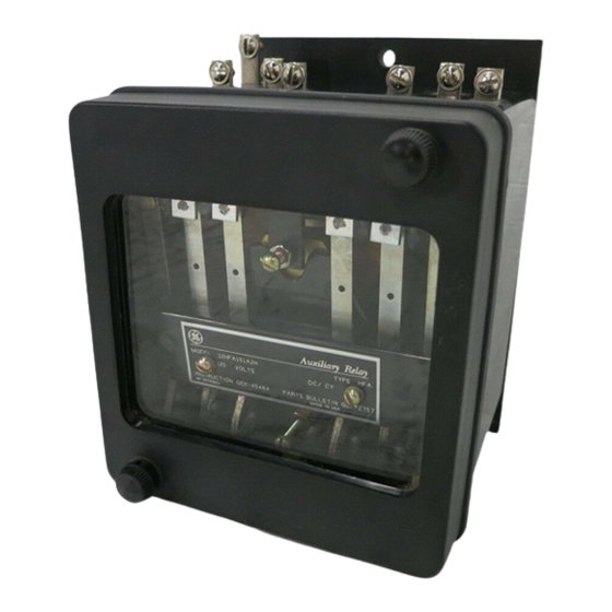
MULTICONTACT AUXILIARY
Type HFA51
DESCRIPTION
auxiliary
to be performed
The front con
one provides mount-
60).
The contact
LOW
VOLTAGE
PHILADELPHIA, PA.
RELAY
peres continuous
Table II lists the non-inductive interrupting capacity
of each contact.
Code No.
Position No.
1
2
3
4
5
6
Note:
a
Normally Open
=
DC
Volts
12
24
32
8
4
1
5
2
250
The burdens are measured with the relay in
the picked up position and at rated voltage are listed
III .
in Table
DC COILS
Watts
Cold
Hot
7.8
6.0
30
SWITCHGEAR DEPARTMENT
.
ELECTRIC
GEH-2024A
SUPERSEDES
or
amperes for one minute.
30
TABLE I
60
51
42
33
24
Contact Arrangement
a
a
a
a
a
a
a
a
a
b
a
b
b
a
b
a
b
b
b
b
a
a
a
b
b
a
a
a
a
a
b
Normally Closed
=
II
TABLE
AC
Volts
115
30
15
230
1
0
460
8
575
3
1
8URDENS
m
TABLE
AC COILS
Freq.
Volt-
Cycles
Amperes
25
10
5
23
0
32
60
GEH·2024
15
06
a
b
b
b
b
b
b
b
b
b
b
b
30
20
15
1
0
Watts
4
9
12
Advertisement

Related Manuals for GE HFA51A


Summary of Contents for GE HFA51A
- Page 1 Volts Volts CHARACTERISTICS The HFA51A relay is self reset and has an instantaneops dropout. The HFA51B relay is hand reset by means of a plunger assembly installed through the transparent cover.
- Page 2 GEH-2024 Multi-contact Auxiliary Relay Type HFAS I Back Connected Re 1 ay in Standard Case Fig. HFA51 Front Connected Relay in Standard Fig. Case ( Front View) (Front View) F ig. 3 � HFA51 Back Connected Relay with Flange for Fig.
- Page 3 Multi-contact Auxiliary Relay Type HFA GEH-2024 Any contact circuit can be changed from cir cuit opening to circuit closing, or vice versa, by removing the fixed contact, turning it over and replacing it. After the change the contacts should be checked to see that all circuit closing contacts make simultaneously when the relay is operated hand, that...
- Page 4 DIA . (2--tiO L ES) I--f� PANEL DRILLING FRONT VIEW OUTLINE Fig, 9 Outline and Panel Drilling for Front Connected Type HFA Relay (Typical Model lumber is HFA51A(-)H) • boo k . Denotes change from superseded GENERAL ELECTRIC COMPANY, PHILADELPHIA, PA.