Paradox PCS250 Installation And Programming Manual
Gprs/gsm communicator module
compatible with insite gold
and swan server
Hide thumbs
Also See for PCS250:
- Reference and installation manual (44 pages) ,
- Reference and installation manual (20 pages)
Advertisement
Quick Links
PCS250
GPRS/GSM Communicator Module
Installation and Programming Guide
**Compatible with Insite GOLD
and SWAN Server**
Installation
1
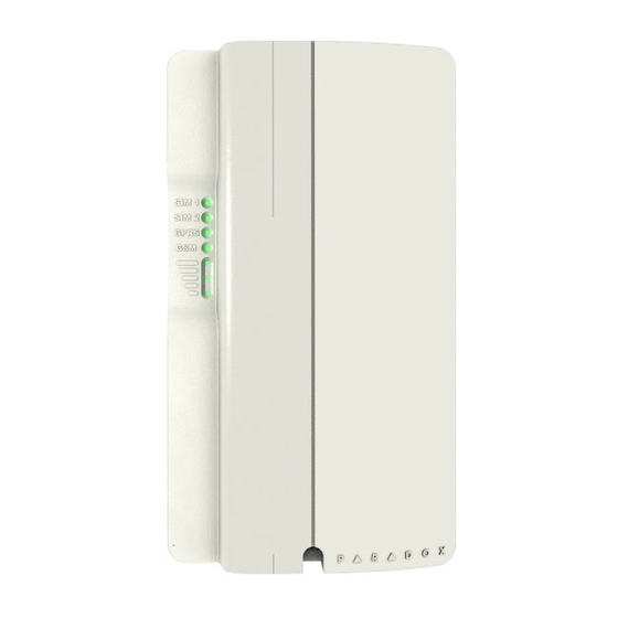
1 Mounting holes
2 Audio jack
2
3 InField upgrade connector
3
4 RS485 / power terminal
5 Serial connector
8
6 Tamper screw hole
4
7 Tamper switch
7
8 Audio module connector
6
5
SIM Card Connection
The PCS250 supports two standard GSM provider SIM cards.
To install the SIM cards, open the SIM Card tray and insert card into slot,
as shown. SIM Card 1 is used as "Primary" and SIM Card 2 for
"Backup".
Panel Connections
Connect the PCS250's serial out to the serial connector on the panel.
• For GPRS reporting, connect to the Serial port of the panel.
• For GSM reporting, connect to the EBUS port of the panel.
GPRS (Serial Connector)
GSM (EBUS Connector)
RS485 Connection
A CVT485 module can be connected onto the control panel's EBUS in
order to lengthen the distance (up to 300 m. / 1000 ft.) between the
panel and the PCS250. Refer to the drawing for connections.
*Optional Power Supply Connections (for RS485)
The PCS250 is designed to be powered by the control panel up to 50m
(160 ft.) with an 18 gauge wire. If you are using a CVT485 module to
increase the distance from your panel, an external power supply should
be used. Refer to the drawing below.
(e.g., VDMP3)
Antenna Extension Connection
Use an antenna extension kit to improve RF reception if your module's
signal strength is weak. Antenna kits are purchased separately.
IP150 Connection
The PCS250 can be connected to the IP150 Internet Module's PCS
port. For more information on how to configure this option, please refer
to the IP150's Installation manual.
UC300 Connection
The PCS250 can be connected to the UC300 Serial port. For more
information on how to configure this option, please refer to the UC300's
Installation manual.
VDMP3 Connection (GSM mode only)
If using a VDMP3 module for personal reporting, mount the VDMP3
directly onto the PCS250 Communicator Module to enable the VDMP3
to dial out using the GSM cell phone network.
CVT485
Up to 300m (1000 ft.)
* Up to 50m (160 ft.) AWG18
12 Vdc
VDMP3 Module
Powering-up the PCS250
Once your hardware connections are completed, the PCS250 module
will begin its power up sequence.
• SIM1, SIM2, GPRS, and GSM LEDs will flash intermittently for
several seconds.
• SIM card 1 LED will slowly flash green while searching for the GSM
network; once found the LED will be solid green and signal strength
LEDs turn on (depending on network strength)
If configured for GPRS reporting, you will need to configure network
provider information. Refer to Programming.
LED Functionality
LED
Functionality
SIM1 and
Solid green - SIM Card 1/2 is installed on the GPRS
SIM2
module
Quick green flashing - SIM card 1/2 is exchanging
data
Slow green flashing - Searching the network
Flash red (once) SIM Card 1/2 is defective
Off - SIM Card 1/2 is not installed, not active, or
currently not in use
GPRS
Solid green - unit is set for GPRS operation
Quick green flashing - exchanging data
(when this LED in ON, the GSM LED stays OFF)
GSM
Solid green - unit is set for GSM operation
Quick green flashing - exchanging data
(when this LED in ON, the GPRS LED stays OFF)
Signal
Three LEDs indicate network strength
Strength
Programming
In order to configure the PCS250 for reporting, you will need to first
configure your SIM cards. Please note that SIM Card 1 can be
configured via panel programming and SIM Card 2 via SMS.
GPRS Reporting (Serial Port Connection)
Network Provider Information
MG/SP
EVO
Feature
[921]
[2960]
APN part 1 (characters 1-16)
[922]
[2961]
APN part 2 (characters 17-32)
[923]
[2962]
APN user name part 1 (1-16)
[924]
[2963]
APN user name part 2 (17-32)
[925]
[2964]
APN password part 1 (1-16)
[926]
[2965]
APN password part 2 (17-32)
Important: This information can be obtained from your mobile network
provider.
Network Provider Information via SMS
Command
Description
P[password].
Used to program the SIM Card 2 Access
APN2.NAME.
Point Name
[Access Point Name]
P[password].
Used to program the SIM Card 2 Access
APN2.USER.
Point User
[Access Point Name]
P[password].APN2.PSW.
Used to program the SIM Card 2 Access
[Access Point Name]
Point Password
P[password].
Used to clear the SIM Card 2 Access Point
APN2.CLEAR
Name
P[password].VAPN2.
Used to view the SIM Card 2 Access Point
[CALL BACK PHONE
Name information
NUMBER]
PCS250-EI07 05/2018
Advertisement

Related Manuals for Paradox PCS250


Summary of Contents for Paradox PCS250
- Page 1 *Optional Power Supply Connections (for RS485) currently not in use 4 RS485 / power terminal The PCS250 is designed to be powered by the control panel up to 50m GPRS Solid green - unit is set for GPRS operation 5 Serial connector (160 ft.) with an 18 gauge wire.
-
Page 2: Technical Specifications
(V4.10.011 and up) Patents SMS Messages for Backup Your use of the Paradox product signifies your acceptance of these terms and conditions. The following US patents may apply 5,886,632 and Command Description 6,215,399. Other Canadian and international patents may apply.
Need help?
Do you have a question about the PCS250 and is the answer not in the manual?
Questions and answers