Table of Contents
Advertisement
Quick Links
MBT-5000
L-Band Up/Down Converter System
Installation and Operation Manual
Part Number MN-MBT5000
Revision 4
IMPORTANT NOTE:
The information contained in this document supersedes all previously published
information regarding this product. Product specifications are subject to change without prior notice.
Part Number MN-MBT5000 Revision 4
Advertisement
Table of Contents

Related Manuals for Comtech EF Data MBT-5000


Summary of Contents for Comtech EF Data MBT-5000
- Page 1 MBT-5000 L-Band Up/Down Converter System Installation and Operation Manual Part Number MN-MBT5000 Revision 4 IMPORTANT NOTE: The information contained in this document supersedes all previously published information regarding this product. Product specifications are subject to change without prior notice. Part Number MN-MBT5000 Revision 4...
- Page 2 Copyright © 2014 Comtech EF Data. All rights reserved. Printed in the USA. Comtech EF Data, 2114 West 7th Street, Tempe, Arizona 85281 USA, 480.333.2200, FAX: 480.333.2161...
-
Page 3: Table Of Contents
European Union RoHS Directive (2002/95/EC) ...................xiii European Union Telecommunications Terminal Equipment Directive (91/263/EEC) ......xiii CE Mark ...............................xiii Product Support ..........................xiii Comtech EF Data Headquarters ....................... xiii Warranty Policy ..........................xiii Limitations of Warranty .......................... xiv Exclusive Remedies ..........................xv CHAPTER 1. - Page 4 ‘J9 | 10/100 ETHERNET’ 10/100 BaseT M&C Port (RJ-45) ..........3–8 3.2.3.4 ‘P1 | RELAY’ Summary Fault Output Connector (DB-9F) ..........3–8 3.2.3.5 ‘J1 | COM 1’ EIA-485/232 Interface Connector (DB-9F) ........... 3–9 MBT-5000 Ground and Power Connections ................ 3–10...
- Page 5 MBT-5000 L-Band Up/Down Converter System MN-MBT5000 Table of Contents Revision 4 3.3.1 Chassis Ground Interface ....................3–10 3.3.2 Alternating Current (AC) Power Interfaces ................. 3–10 3.3.2.1 Standard 90-260V Alternating Current (AC) Power Interface ........3–10 3.3.2.1.1 Standard 90-260V AC Operation – Apply Power ............3–11 3.3.2.1.2 Standard 90-260V AC Operation –...
- Page 6 MBT-5000 L-Band Up/Down Converter System MN-MBT5000 Table of Contents Revision 4 5.2.3.2 Monitor: Mask......................... 5–12 5.2.3.2.1 Out-of-Range Power Supply Masking Using the PS Submenu ........5–13 5.2.3.3 Monitor: Event-Log (Stored Events)................5–14 5.2.3.3.1 Stored Events: View ....................5–14 5.2.3.3.2 Stored Event: Clear-All ....................5–14 5.2.3.4...
- Page 7 End of Packet ........................7–7 Remote Commands and Queries ..................7–8 7.3.1 MBT-5000 Base Unit Remote Commands and Queries ............7–9 7.3.2 Block Converter (BUC / BDC) Remote Commands and Queries ......... 7–19 APPENDIX A. BUC-5000X/BDC-5000X MODULE REMOVAL/INSTALLATION ....A–1 Overview ...........................
- Page 8 Figure 3-10. Apply DC Power to the MBT-5000 ..................3–13 Figure 3-11. Replace the MBT-5000 DC Fuse ..................3–14 Figure 5-1. MBT-5000 Front and Rear Panel Views (Redundant Unit Shown) ......... 5–1 Figure 5-2. MBT-5000 Rear Panel Power Interface Examples ..............5–2 Figure 5-3.
-
Page 9: Preface
MBT-5000. Disclaimer Comtech EF Data has reviewed this manual thoroughly in order to provide an easy-to-use guide to this equipment. All statements, technical information, and recommendations in this manual and in any guides or related documents are believed reliable, but the accuracy and completeness thereof are not guaranteed or warranted, and they are not intended to be, nor should they be understood to be, representations or warranties concerning the products described. -
Page 10: Examples Of Multi-Hazard Notices
The new designation of the Electronic Industries Association (EIA) supersedes the Recommended Standard (RS) designations. References to the old designations may be shown when depicting actual text (e.g., RS-232) displayed on the MBT-5000 Web Server pages or serial remote interface. All other references in the manual refer to EIA designations. -
Page 11: Electrical Installation
CAUTION – CONNECT THE UNIT TO A POWER SYSTEM THAT HAS SEPARATE GROUND, LINE, AND NEUTRAL CONDUCTORS. DO NOT CONNECT THE UNIT WITHOUT A DIRECT CONNECTION TO GROUND. Chapter 3.3 MBT-5000 GROUND AND POWER CONNECTIONS Operating Environment CAUTION – DO NOT OPERATE THE UNIT IN ANY OF THESE EXTREME OPERATING CONDITIONS: •... -
Page 12: European Union Low Voltage Directive (Lvd) (2006/95/Ec)
MBT-5000 L-Band Up/Down Converter System MN-MBT5000 Preface Revision 4 • EN 61000-3-3 – Voltage Fluctuations and Flicker. • Federal Communications Commission Federal Code of Regulation FCC Part 15, Subpart B. This equipment complies with the limits for a Class A digital device. These limits are designed to provide reasonable protection against harmful interference when the equipment is operated in a commercial environment. -
Page 13: European Union Rohs Directive (2002/95/Ec)
In accordance with the European Union Telecommunications Terminal Equipment Directive 91/263/EEC, the unit should not be directly connected to the Public Telecommunications Network. CE Mark Comtech EF Data declares that the unit meets the necessary requirements for the CE Mark. Product Support For all product support, please call: +1.240.243.1880 +1.866.472.3963 (toll free USA) -
Page 14: Limitations Of Warranty
The warranty does not apply to any part of a product that has been installed, altered, repaired, or misused in any way that, in the opinion of Comtech EF Data Corporation, would affect the reliability or detracts from the performance of any part of the product, or is damaged as the result of use in a way or with equipment that had not been previously approved by Comtech EF Data Corporation. -
Page 15: Exclusive Remedies
Preface Revision 4 A fixed charge established for each product will be imposed for all equipment returned for warranty repair where Comtech EF Data Corporation cannot identify the cause of the reported failure. Exclusive Remedies Comtech EF Data Corporation’s warranty, as stated is in lieu of all other warranties, expressed, implied, or statutory, including those of merchantability and fitness for a particular purpose. - Page 16 MBT-5000 L-Band Up/Down Converter System MN-MBT5000 Preface Revision 4 Notes:...
-
Page 17: Chapter 1. Introduction
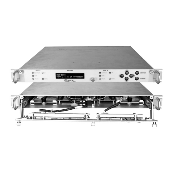
The unit may be freestanding if desired. All operator controls, indicators and displays for local and remote operation are located on the front panel of the MBT-5000. The drop-down design of the front panel provides user access to the two internal upconverter or downconverter modules. -
Page 18: Figure 1-2. Mbt-5000 Operational Schematics
Introduction Revision 4 External interface connectors are located on the rear panel of the MBT-5000 chassis. External equipment, e.g., a modem, is connected to each internal converter module via a standard, off- the-shelf coaxial cable. A coaxial cable is also used to connect the output for each module to RF equipment either at the same location or at the antenna location. -
Page 19: Features
MBT-5000 L-Band Up/Down Converter System MN-MBT5000 Introduction Revision 4 Features • Meets or exceeds IESS-308/309 • Low phase noise • 20 dB gain adjustment • Flexible configuration • RF Band switching in minimal time without requiring tools • Optional 1:1 Redundancy 1.3.1... -
Page 20: Summary Of Specifications
MBT-5000 L-Band Up/Down Converter System MN-MBT5000 Introduction Revision 4 Summary of Specifications 1.4.1 Physical & Environmental Weight 15 lbs. (6.80 kg) Nominal Dimensions (excluding connectors) See Figure 1-3 Operating 32º to 132.8ºF (0º to 56ºC) Temperature Non-operating (Storage) -58º to 158ºF (-50º to 70ºC) -
Page 21: Buc-5000X Block Upconverters
MBT-5000 L-Band Up/Down Converter System MN-MBT5000 Introduction Revision 4 1.4.5 BUC-5000x Block Upconverters Model RF Output IF Input BUC-5000C 5850-6425 MHz 950-1525 MHz 4900 MHz Optional 5850-6650 MHz 950-1750 MHz Optional 5850-6725 MHz 950-1825 MHz BUC-5000CI (Inverted) 5850-6425 MHz 950-1525 MHz... -
Page 22: Bdc-5000X Block Downconverters
MBT-5000 L-Band Up/Down Converter System MN-MBT5000 Introduction Revision 4 1.4.6 BDC-5000x Block Downconverters Model RF Output IF Input BDC-5000C 3400-4200 MHz 950-1750 MHz 5150 MHz BDC-5000CNI 3625-4200 MHz 1325-1900 MHz 2300 MHz (Non-Inverting BDC-5000X 7250-7750 MHz 950-1450 MHz 6300 MHz... -
Page 23: Dimensional Envelope
MBT-5000 L-Band Up/Down Converter System MN-MBT5000 Introduction Revision 4 Dimensional Envelope Figure 1-3. MBT-5000 Dimensional Envelope 1–7... - Page 24 MBT-5000 L-Band Up/Down Converter System MN-MBT5000 Introduction Revision 4 Notes: 1–8...
-
Page 25: Chapter 2. Installation
Unpack and Inspect the Shipment Figure 2-1. Unpacking and Inspecting the MBT-5000 The MBT-5000 L-Band Up/Down Converter System, its optional Installation and Operation Manual (otherwise available online at http://www.comtechefdata.com), and its power cord were packaged and shipped in a reusable cardboard carton containing protective foam spacing. -
Page 26: Install The Unit Into A Rack Enclosure
Comtech EF Data to submit a damage report. Read the manual. Install the Unit Into a Rack Enclosure Install the MBT-5000 in its assigned position in the rack enclosure (Figure 2-2). Use, as required: • A standard rack-mounted shelf;... -
Page 27: Figure 2-2. Install The Unit Into A Rack Enclosure
MBT-5000 L-Band Up/Down Converter System MN-MBT5000 Installation Revision 4 Feature Description Custom Rack Enclosure MBT-5000 Up/Down Converter System Standard Rack Shelving Rack Enclosure Threaded Front Rail (typical) Unit Front Panel User-supplied Screws Figure 2-2. Install the Unit into a Rack Enclosure... -
Page 28: 2.2.1 Install The Optional Rear-Mounting Support Brackets Kit
MBT-5000 L-Band Up/Down Converter System MN-MBT5000 Installation Revision 4 2.2.1 Install the Optional Rear-Mounting Support Brackets Kit Use the follwing tools to install the KT/6228-2 (4”) or KT/6228-3 (10”) Rear-Mounting Support Brackets Kit ( Figure 2-3) • A medium Phillips screwdriver •... -
Page 29: 2.2.2 Install The Optional Bearingless Rack Slide Set
If you wish to mount the converter on slides, you may install an optional bearingless rack slide set (Figure 2-4) into the rack cabinet and onto the sides of the MBT-5000. Use the hardware provided with the slide set that is appropriate for your specific installation:... -
Page 30: Figure 2-4. Optional Bearingless Rack Slide Installation (Fp/Sl000X)
MBT-5000 L-Band Up/Down Converter System MN-MBT5000 Installation Revision 4 Figure 2-4. Optional Bearingless Rack Slide Installation (FP/SL000X) 2–6... -
Page 31: Chapter 3. Rear Panel Connections
(Type ‘N’ shown) Figure 3-1. Coaxial Connector Examples The types of coaxial cables used by Comtech EF Data are ‘BNC’, ‘TNC’, ‘N’, ‘F’, and ‘SMA’. Coaxial cables (plugs) and their mating connectors (jacks/sockets) are available in two coupling styles –... -
Page 32: Type 'Bnc
MBT-5000 L-Band Up/Down Converter System MN-MBT5000 Rear Panel Connections Revision 4 • Bayonet Coupling Style: The jack has a pair of guide posts that accommodate the plug’s lockdown slots. This lockdown design provides secure assembly without over-tightening the connection. •... -
Page 33: Type 'F
MBT-5000 L-Band Up/Down Converter System MN-MBT5000 Rear Panel Connections Revision 4 3.1.1.4 Type ‘F’ Type ‘F’ connectors feature a Threaded Coupling design similar to Type ‘TNC’, Type ‘N’, and Type ‘SMA’ connectors. 3.1.1.5 Type ‘SMA’ (Subminiature Version ‘A’) Type ‘SMA’ connectors feature a Threaded Coupling design similar to Type ‘TNC’, Type ‘N’, and Type ‘F’... -
Page 34: Rj-45, Rj-48 Cable Connections
MBT-5000 L-Band Up/Down Converter System MN-MBT5000 Rear Panel Connections Revision 4 Connection Instructions: Orient the plug to the receptacle in the proper position. Press firmly into place. Use the jack screws to secure the plug to the receptacle jack nuts. Do not over- tighten. -
Page 35: Mbt-5000 Cabling Connections
(Optional Redundancy Unit w/Standard AC Power Shown) Figure 3-3. MBT-5000 Cabling Connections The MBT-5000 rear panel connectors, shown here in Figure 3-1, provide all necessary external connections between the unit and other equipment. The table that follows summarizes the connectors provided here, grouped according to service function. -
Page 36: If Connector Group
3.2.1 IF Connector Group These connectors are integral components of the BUC/BDC modules installed in the MBT-5000 chassis Side A and Side B module bays. Appendix A. BUC-5000x/BDC-5000x MODULE REMOVAL/INSTALLATION 3.2.1.1 ‘J4 | IF OUT/IN’ (Side B) Connector (Type ‘N’ Female) -
Page 37: Optional Redundancy Groups
Optional Redundancy Groups See the “Function” column in Table 3-1 in this chapter, and Figure B-2 in Appendix B. MBT-5000 REDUNDANCY OPERATION for interconnection between these connectors to others located on the MBT-5000 rear panel and on other external equipment. 3.2.2.1 Optional ‘RF’... -
Page 38: J9 | 10/100 Ethernet' 10/100 Baset M&C Port (Rj-45)
This standard RJ-45 female modular jack is used for product M&C using SNMP, Telnet, and HTTP. It is also used for MBT-5000 firmware updates. A CAT5e UTP cable is used to connect to an Ethernet hub, router, switch, PC, etc. -
Page 39: J1 | Com 1' Eia-485/232 Interface Connector (Db-9F)
MBT-5000 L-Band Up/Down Converter System MN-MBT5000 Rear Panel Connections Revision 4 ‘J1 | COM 1’ EIA-485/232 Interface Connector (DB-9F) Chapter 7. SERIAL-BASED REMOTE PRODUCT MANAGEMENT This EIA-485/EIA-232 interface connector is a 9-pin Type "D"female connector (DB-9F). Its mating connector is a DB-9M connector. -
Page 40: Mbt-5000 Ground And Power Connections
The AC power interface provides the safety ground. (Optional Redundancy Unit w/Standard AC Power Shown) Figure 3-4. MBT-5000 Chassis – Common Ground Interface This #10-32 stud is located at a common chassis location to the left-hand side of the standard AC, optional dual AC, or optional DC power module (Figure 3-4). -
Page 41: Standard 90-260V Ac Operation - Apply Power
CAUTION – FOR CONTINUED OPERATOR SAFETY, ALWAYS REPLACE THE FUSES WITH THE CORRECT TYPE AND RATING. The MBT-5000 uses two 20mm slow-blow fuses – one each for line and neutral connections (L1, L2 where appropriate). The fuses are located in the rear panel at the IEC AC power supply module (Figure 3-7). -
Page 42: Optional Dual Entry Module Alternating Current (Ac) Power Interface (Redundancy Units Only)
Use T2.0A (2 Amp) fuses for standard operation. • Finally, re-seat the fuse holder in the IEC power module. 3.3.2.2 Optional Dual Entry Module Alternating Current (AC) Power Interface (Redundancy Units Only) Figure 3-8. MBT-5000 Optional Dual Entry Module AC Power Interface 3–12... -
Page 43: Optional -48V Direct Current (Dc) Power Interface
Optional -48V DC Operation – Apply Power Figure 3-10. Apply DC Power to the MBT-5000 To apply DC power to the MBT-5000, do these steps: • First, connect the user-supplied (+) and (–) DC power leads to their respective terminals. -
Page 44: Optional -48V Dc Operation - Replace The Fuse
CAUTION – FOR CONTINUED OPERATOR SAFETY, ALWAYS REPLACE THE FUSES WITH THE CORRECT TYPE AND RATING. The optional -48V DC MBT-5000 uses a single 20mm slow-blow fuse. A latched fuse holder is located on the rear panel, on the DC power supply (terminal block) module (Figure 3-11). -
Page 45: Chapter 4. Upgrading Firmware
You may perform the firmware update, without opening the MBT-5000, remotely over satellite, or by directly connecting a user-supplied Microsoft Windows-based PC to the ‘J9 | 10/100 ETHERNET’ port and the 9-pin serial ‘J1 | COM 1’ port located on the MBT-5000 rear panel. Do these steps: •... -
Page 46: Getting Started: Prepare For The Firmware Download
Web browser (e.g., Internet Explorer); and a terminal emulator program (e.g., Tera Term or HyperTerminal). • A 9-pin serial cable and a standard CAT5 Ethernet cable to connect the MBT-5000 to the user PC. A. Use an Ethernet hub, switch, or direct cable connection to connect the MBT-5000 rear panel ‘J9 | 10/100 ETHERNET’... - Page 47 Image#2 Bulk menu branches, as shown in this example: Bulk:FW-000303 2.1.X MM/DD/YY Using the MBT-5000 HTTP Interface (via the User PC Web Browser – use of this interface indicates the Ethernet Traffic IP Address is already known): • Firmware Info – Use the “Firmware...
- Page 48 MBT-5000 L-Band Up/Down Converter System MN-MBT5000 Upgrading Firmware Revision 4 2) Next, create a temporary folder (subdirectory) on the user PC for the firmware archive download. • Drive letter “c:” is used in these examples. Any valid, writable drive letter can be used.
- Page 49 MBT-5000 L-Band Up/Down Converter System MN-MBT5000 Upgrading Firmware Revision 4 • Click the Create New Folder icon in the ‘Browse’ window. This creates the new folder. • Right-click the “New Folder” folder name, and then rename this folder to “MBT5000” or some other convenient, unused name: D.
-
Page 50: Download And Extract The Firmware Update
4.2.1 Download and E xtrac t the F irmware Update 1) First, download the firmware update file from the Comtech EF Data Web site: A. Go online to www.comtechefdata.com. B. On the Main page – under Support Information or the Support tab, select the Software Downloads hyperlink. - Page 51 MBT-5000 L-Band Up/Down Converter System MN-MBT5000 Upgrading Firmware Revision 4 ReleaseNotes_MBT5000_#.#.#.pdf – the Firmware Release Notes PDF file. 3) Confirm availability of the firmware files in the temporary folder. There are several ways you may view the contents of the temporary folder on a Windows- based PC: A.
-
Page 52: Perform The Ethernet Ftp Upload Procedure
You have connected the MBT-5000 to a user-supplied, Windows-based PC, and: o The User PC serial port is connected to the MBT-5000 ‘J1 | COM 1’ port with a standard user serial cable. o The User PC Ethernet port is connected to the MBT-5000 ‘J9 | 10/100 ETHERNET’... - Page 53 Serial Remote Interface <0/SWR? or <0/FRW? query as shown previously to verify that the PC-to-Unit FTP file transfer was successful. 4) Use the converter front panel menus or the the MBT-5000 HTTP Interface to select the desired firmware image to boot from: A.
- Page 54 MBT-5000 Version: #.#.# SN ####### 6) To load the second Firmware Image, use the converter front panel or the MBT-5000 HTTP Interface ‘Config | Utility’ page to configure the target Image (1 or 2) as the Current Active Firmware Image, and then repeat Steps 2 through 5.
-
Page 55: Chapter 5. Front Panel Operation
Standard AC Unit Power Switch REAR IEC Line Input AC Power Connector module and the optional -48V PANEL Optional -48V DC Unit Power Switch DC Power Terminal module. Figure 5-1. MBT-5000 Front and Rear Panel Views (Redundant Unit Shown) 5–1... -
Page 56: Switch Power On (Rear Panel)
Before you turn on power to the unit, make sure that installation is complete, and verify that the MBT-5000 is connected to the proper prime power source, RF Input, and RF Output. Switch on the unit and verify the cooling fan is operational, the LED indicators illuminate as expected, and the Vacuum Fluorescent Display is readable. -
Page 57: Keypad
Use these keys primarily to change the alphanumeric selection (i.e., numbers for configuration data, letters for text strings) at the current cursor position, or to scroll through pre-defined parameter settings that the MBT-5000 may provide at the current cursor position. (Up, Down) 5.1.4... -
Page 58: Opening Screen
Front Panel Operation Error! Reference source not found. shows the hierarchal structure of the MBT-5000 menu tree from the SELECT: (Main) menu on down. The structure helps to prevent invalid command entry. Figure 5-3. MBT-5000 Front Panel Menu Tree (Firmware Ver. 2.5.1) -
Page 59: Select: (Main) Menu
Menu Branch Sect Function Config 5.2.2 (Configuration) Used to fully configure the MBT-5000. Used to monitor the alarm status of the unit, to view the log of stored events, and to Monitor 5.2.3 display the Receive Parameters screen. (Information) Used to view information on the unit, without having to go into Info 5.2.4... -
Page 60: Select: Config (Configuration) Menu Branches
(Reference Oscillator Adjustment) Used to adjust the reference oscillator. (Redundancy) Used to identify the redundancy state and mode (see Appendix B. Redun 5.2.2.5 MBT-5000 REDUNDANCY OPERATION for further information). 5.2.2.1 CONFIG: Remote (Remote Control) Menus Remote Control: Local Serial Ethernet (◄... -
Page 61: Remote Control: Ethernet
MBT-5000 L-Band Up/Down Converter System MN-MBT5000 Front Panel Operation Revision 4 Serial Config: Address Remote Address: 0001 (◄ ► ▲ ▼ E) The valid range of addresses is from 1 to 9997. Use the ◄ ► arrow keys to select the digit to edit, and then use the ▼▲arrow keys to change the value of that digit. - Page 62 All printable ASCII characters are available with the exception of the backslash ‘/’ (ASCII code 92) and tilde ‘~’ (ASCII code 126). Press ENTER once you compose the string – the MBT-5000 removes all trailing spaces from the string upon entry.
-
Page 63: Config: Fltrec (Fault Recovery) Menu
MBT-5000 L-Band Up/Down Converter System MN-MBT5000 Front Panel Operation Revision 4 SNMP: Traps SNMP Trap IP Address: IP1 IP2 Version Use the ◄ ► arrow keys to select IP1, IP2, or Version, and then press ENTER. SNMP Trap IP Address: IP1 or IP2 Trap IP #1: 000.000.000.000(◄... -
Page 64: Converter X: Mute/Freq
MBT-5000 L-Band Up/Down Converter System MN-MBT5000 Front Panel Operation Revision 4 5.2.2.3.1 Converter X: Mute/Freq For either side – A or B – the display differs depending on whether the selected module is a BUC or BDC. For example, if you select Converter A and it is a BUC:... -
Page 65: Config: Redun (Redundancy) Menus
5.2.2.5 CONFIG: Redun (Redundancy) Menus 1:1 Redundancy is an optional feature for the MBT-5000. When you attempt to select this menu branch, but your MBT-5000 is configured as a standalone up/down converter system (e.g., a non- redundant configuration, where a BUC is installed in Side A, and a BDC is installed in Side B) the following message displays: Redundancy is Disabled. -
Page 66: Select: Monitor Menu Branch
MBT-5000 L-Band Up/Down Converter System MN-MBT5000 Front Panel Operation Revision 4 5.2.3 SELECT: Monitor Menu Branch Monitor: Faults Mask Event-Log Use the ◄ ► arrow keys to select from the submenu choices shown, and then press ENTER. The submenus available from the SELECT: Monitor menu branch are as follows:... -
Page 67: Out-Of-Range Power Supply Masking Using The Ps Submenu
MBT-5000 L-Band Up/Down Converter System MN-MBT5000 Front Panel Operation Revision 4 Use the ◄ ► arrow keys to select Fault, Alarm, or Masked, and then press ENTER to return to the previous menu. If Power Monitoring is not supported when you select Power alarm masking, the... -
Page 68: Monitor: Event-Log (Stored Events)
Use the ▼▲ arrow keys to scroll backwards or forwards through the entries in the event log. The event log can store up to 300 events. When a fault condition occurs, the MBT-5000 time- stampa it and puts it into the log. Similarly, when the fault condition clears, MBT-5000 records... - Page 69 MBT-5000 L-Band Up/Down Converter System MN-MBT5000 Front Panel Operation Revision 4 Use the ◄ ► arrow keys to first select the digit to edit, and then use the ▼▲ arrow keys to edit the value of that digit. Note the following: •...
-
Page 70: Select: Info (Information) Menu Branch
MBT-5000 L-Band Up/Down Converter System MN-MBT5000 Front Panel Operation Revision 4 5.2.4 SELECT: Info (Information) Menu Branch INFO:Remote ConvA ConvB PSA PSB RefOsc The Info menu branch displays read-only information on the current configuration of the unit. Use the ◄ ► arrow keys to select from the submenu choices shown, and then press ENTER. -
Page 71: Info: Psa Or Psb (Power Supply 'A' Or Power Supply 'B')
MBT-5000 L-Band Up/Down Converter System MN-MBT5000 Front Panel Operation Revision 4 5.2.4.3 INFO: PSA or PSB (Power Supply ‘A’ or Power Supply ‘B’) Where ‘X’ is the selected converter – Converter (Side) A or Converter (Side) B: This screen screen displays the 12V, 7.8V, and 5V values for PSA (Power Supply ‘A’), and the 12V and 5V values for PSB (Power Supply ‘B’). -
Page 72: Select: Utility Menu Branch
A maximum of 24 characters are available, as follows: [Space] ( ) * + - , . / 0-9 and A-Z. Press ENTER once you compose the string – the MBT-5000 removes all trailing spaces from the string upon entry. -
Page 73: Utility: Display (Vfd Display Brightness)
CHANGE AN IMAGE UNLESS OTHERWISE INSTRUCTED BY COMTECH EF DATA PRODUCT SUPPORT. This series of submenus permits you to view information about the MBT-5000 internal firmware. The MBT-5000 can store two complete firmware images. You can select which image loads the next time the unit reboots. Firmware Images: Info Select (◄... -
Page 74: Firmware Images: Select
UTILITY: LNA LNA: ConvA ConvB When the MBT-5000 has an LNA current supply, this screen permits you to enable or disable the LNA operation, allow calibration of the LNA reference current, and set the window (range) for alarms and faults. -
Page 75: Select: Test Menu Branch
MBT-5000 L-Band Up/Down Converter System MN-MBT5000 Front Panel Operation Revision 4 ConvX LNA: Calibr (Calibrate Reference Current) ConvX LNA Ref = 400.0 mA Calibrate: No Yes (◄ ► E) On the bottom line, use the ◄ ► arrow keys to select No or Yes, and then press ENTER. If you select Yes and the LNA successfully calibrates, the current value appears on the top line of the screen (e.g., 400.0 mA). - Page 76 MBT-5000 L-Band Up/Down Converter System MN-MBT5000 Front Panel Operation Revision 4 Notes: 5–22...
-
Page 77: Chapter 6. Ethernet-Based Remote Product Management
The MBT-5000 is connected to a user-supplied Windows-based PC as follows: o The PC’s serial port is connected to the MBT-5000 rear panel ‘J1 COM 1’ serial port with a user-supplied serial cable. o The PC’s Ethernet port is connected to the MBT-5000 rear panel ‘J9 10/100 ETHERNET’... -
Page 78: Ethernet Management Interface Protocols
MBT-5000 HTTP (Web Server) Interface. This requires a compatible user-supplied Web browser such as Internet Explorer. For SNMP, Telnet, or HTTP operation, the MBT-5000 must be configured with the Ethernet control option. Via the front panel, select CONFIG: Remote Control ... -
Page 79: Snmp Interface
The managed device. This includes the MBT-5000. • The SNMP Agent. This is the software that runs on the MBT-5000. The MBT-5000 SNMP • Agent supports both SNMPv1 and SNMPv2c. The user-supplied Network Management System (NMS). This is the software that runs on •... -
Page 80: 6.3.3 Snmp Traps
SNMP traps when certain events occur in the unit. A trap is sent both when a fault occurs and is cleared. You may configure which style of traps the MBT-5000 sends by using the MBT-5000SNMPTrapVersion OID. -
Page 81: Telnet Interface
Revision 4 Telnet Interface The MBT-5000 provides a Telnet interface for the purpose of Equipment M&C via the standard equipment Remote Control protocol. The Telnet interface requires user login at the Administrator level and Read/Write level. An example of the login process is shown here: Once logged into the Telnet interface as Administrator, you can access the standard remote control interface defined in Chapter 7. -
Page 82: 6.4.1 Telnet Operation Via Hyperterminal
FRW? query) will be displayed as one line, with the latter lines overwriting the previous lines. In order to view the full response messages, Comtech EF Data recommends use of the HyperTerminal terminal emulation program, configured as a Telnet client. -
Page 83: Http (Web Server) Interface
Revision 4 HTTP (Web Server) Interface A user-supplied Web browser allows the full monitor and control (M&C) of the MBT-5000 from its HTTP Interface. This non-secure, embedded Web application is designed for, and works best with, Microsoft’s Internet Explorer Version 5.5 or higher (the examples shown use Internet Explorer Version 7.0). -
Page 84: 6.5.2 User Login
Failure to enter the correct User name and Password will return you to a blank Login window. Otherwise, once the valid IP address and login information is entered, the MBT-5000 Web Server Interface “Splash” page is displayed, similar to the example shown here:... -
Page 85: 6.5.3 Web Server Interface - Operational Features
6.5.3.3 Action Buttons Action buttons are important in the MBT-5000 HTTP Interface. Click an action button to do one of these tasks: • Reset changed parameters to remove unsaved changes. -
Page 86: Text Or Data Entry
If you edit any field, make sure to click the action button before you leave the page. If you go to another page without first clicking the action button, your changes are saved. 6.5.4 Web Server Interface – Menu Tree Navigation of the MBT-5000 HTTP Interface is illustrated with this menu tree: Home Admin Config... -
Page 87: Web Server Interface
Select the Home hyperlink to continue. 6.5.5.1.1 Home | Home From any location within the MBT-5000 Web Server Interface, click the Home top navigation tab and/or the nested hyperlink to return back to this top-level page. Use this page to identify the product. -
Page 88: Admin
Administrator Name and Password. The Administrator may use these pages to: Set up user names, passwords, the e-mail server, and the host IP Addresses as required for communication with the MBT-5000 Web Server Interface. Click the Access or SNMP hyperlink to continue. - Page 89 MBT-5000 L-Band Up/Down Converter System MN-MBT5000 Ethernet-based Remote Product Management Revision 4 System Account Access Information • Admin, Read/Write, and Read Only Names and Passwords: The factory defaults for these names/passwords are: o Admin comtech/comtech o Read/Write opcenter/1234 o Read Only...
-
Page 90: Admin | Snmp
MN-MBT5000 Ethernet-based Remote Product Management Revision 4 6.5.5.2.2 Admin | SNMP Use this page to set and returns administration information for the MBT-5000 Simple Network Management Protocol (SNMP) feature. Figure 6-3. Admin | SNMP page SNMP • Simple Network Management Operational Status: Use the drop-down list to select the Simple Network Management operational setting as Enabled or Disabled. -
Page 91: Config
Config Pages Select the MBT, Utility, or Redundancy hyperlink to continue. 6.5.5.3.1 Config | MBT Use this page to configure the communications, operations, and alarms/faults handling for the MBT-5000 base unit and separate converters. Figure 6-4. Config | MBT page 6–15... - Page 92 Click [Change Convert X Configuration] (where ‘X’ designates Converter A or Converter B) to save. Converter A / B LNA and LPT Typical for both sections, when the MBT-5000 down converter (BDC) is optionally equipped and configured: • LNA Current Source: Use the drop-down list to select this feature as Enabled or Disabled.
- Page 93 MBT-5000 L-Band Up/Down Converter System MN-MBT5000 Ethernet-based Remote Product Management Revision 4 Any LNA current reading that is outside the window may generate an alarm, a fault, or may be masked entirely depending on the state of the user configured fault mask (see the MSK command syntax in Chapter 7.
-
Page 94: Config | Utility
Current Active Firmware Image. Next Reboot Image Use the drop-down list to select Reboot Image 1 or 2. Press [Submit] when done. Perform Soft Reboot Click [Reboot Now] to reboot the MBT-5000 using the Current Active Firmware Image. 6–18... -
Page 95: Config | Redundancy
Use this page to configure the MBT-5000’s Redundancy Switch Mode. Figure 6-6. Config | Redundancy page Use the drop-down list to Enable or Disable Redundancy Mode. Then, click [Change Redundancy Mode] to update MBT-5000 operation to this selected Redundancy Mode status. 6–19... -
Page 96: Status
Click the Events or Status hyperlink to continue. 6.5.5.4.1 Status | Events Use this page to review pertinent information about stored events, and to define the MBT-5000 alarm parameters that determine how those events are triggered. Figure 6-7. Status | Events page... - Page 97 MBT-5000 L-Band Up/Down Converter System MN-MBT5000 Ethernet-based Remote Product Management Revision 4 • Clear Events Log: Select to clear all stored events from the log. • Initialize Events Pointer: Select to reset the internal pointer to allow queries to start at the beginning of the stored events log.
-
Page 98: Status | Status
Note the following: • Valid ConvA/ConvB LNA Current readings are provided only if the pertinent MBT-5000 down converter (BDC) is optionally configured with an LNA. These parameters otherwise will display as N/A if the pertinent converter is a BUC. - Page 99 This scrollable window identifies the Bootrom, Bulk Image#1 and Bulk Image #2. Base Unit Part Number The part number for the MBT-5000 chassis (i.e., the “base unit”) is identified here. Converter A or B Part Number Type These scrollable Part Number windows identify the part numbers for the converter modules installed in the ‘A’...
- Page 100 MBT-5000 L-Band Up/Down Converter System MN-MBT5000 Ethernet-based Remote Product Management Revision 4 Notes: 6–24...
-
Page 101: Chapter 7. Serial-Based Remote Product Management
• The MBT-5000 is connected to a user-supplied Windows-based PC as follows: o The PC’s serial port is connected to the MBT-5000 rear panel ‘J1 COM 1’ serial port with a user-supplied serial cable. o The PC’s Ethernet port is connected to the MBT-5000 rear panel ‘J9 10/100 ETHERNET’ port with a user-supplied hub, switch, or direct Ethernet cable connection. -
Page 102: Eia-485
AND CONTROL (M&C) OF THE MBT-5000. SEE CHAPTER 6. ETHERNET-BASED REMOTE PRODUCT MANAGEMENT. MBT-5000 Serial Remote Product Management is available through the rear panel serial interface. This electrical interface is either an EIA-485 multi-drop bus (for the control of many devices) or an EIA-232 connection (for the control of a single device), and data is transmitted in asynchronous serial form, using ASCII characters. -
Page 103: Remote Commands And Queries Overview
• Controller-to-Target: The Controller device (e.g., the user PC/CLI) is used to transmit instructions (commands) to – or to request information from (queries) – the Target device (i.e., the MBT-5000). • Target-to-Controller: The Target, in return, only transmits response information to the Controller when specifically directed by the Controller. -
Page 104: Packet Structure
MBT-5000 L-Band Up/Down Converter System MN-MBT5000 Serial-based Remote Product Management Revision 4 7.2.2 Packet Structure The exchange of information is transmitted, Controller-to-Target and Target-to-Controller, in packets. Each packet contains a finite number of bytes consisting of printable ASCII characters, excluding ASCII code 127 (DELETE). -
Page 105: Start Of Packet
Block Converter B Base + 2 If several devices share an EIA-485 bus, it must be noted that the MBT-5000 will require three addresses, and should be spaced apart accordingly. The Controller sends a packet with the address of a Target – the destination of the packet. When the Target responds, the address used is the same address, to indicate to the Controller the source of the packet. -
Page 106: Instruction Code
MBT-5000 L-Band Up/Down Converter System MN-MBT5000 Serial-based Remote Product Management Revision 4 7.2.2.4 Instruction Code This is a three-character alphabetic sequence that identifies the message subject. Wherever possible, the instruction codes have been chosen to have some significance – e.g., FRE for Operating FREquency, IPA for Management IP Address, etc. -
Page 107: Optional Message Arguments
MBT-5000 L-Band Up/Down Converter System MN-MBT5000 Serial-based Remote Product Management Revision 4 Character Definition If the Controller sends an instruction to set a parameter to a particular value, and the value sent is not valid, the Target then acknowledges the message and responds with, for example, MUT? (with no message arguments). This indicates that there was an (ASCII code 63) error in the message sent by the Controller. -
Page 108: Remote Commands And Queries
Remote Commands and Queries The table that follows provides a ‘quick reference‘ to the Instruction Codes available at present for M&C of the MBT-5000. The ‘C’ and ‘Q’ columns, where marked with an ‘X’, denote whether that Instruction Code is Command Only, Query Only, or Command and Query. -
Page 109: Mbt-5000 Base Unit Remote Commands And Queries
MBT-5000 L-Band Up/Down Converter System MN-MBT5000 Serial-based Remote Product Management Revision 4 7.3.1 MBT-5000 Base Unit Remote Commands and Queries Command Arguments for Response to Query Response to query Parameter (Instruction Command or Description of Arguments Command (Instruction (Target to... - Page 110 MBT-5000 L-Band Up/Down Converter System MN-MBT5000 Serial-based Remote Product Management Revision 4 Command Arguments for Response to Query Response to query Parameter (Instruction Command or Description of Arguments Command (Instruction (Target to Type Code and Response to (Note that all arguments are ASCII numeric codes between 48 and 57)
- Page 111 MBT-5000 L-Band Up/Down Converter System MN-MBT5000 Serial-based Remote Product Management Revision 4 Command Arguments for Response to Query Response to query Parameter (Instruction Command or Description of Arguments Command (Instruction (Target to Type Code and Response to (Note that all arguments are ASCII numeric codes between 48 and 57)
- Page 112 MBT-5000 L-Band Up/Down Converter System MN-MBT5000 Serial-based Remote Product Management Revision 4 Command Arguments for Response to Query Response to query Parameter (Instruction Command or Description of Arguments Command (Instruction (Target to Type Code and Response to (Note that all arguments are ASCII numeric codes between 48 and 57)
- Page 113 MBT-5000 L-Band Up/Down Converter System MN-MBT5000 Serial-based Remote Product Management Revision 4 Command Arguments for Response to Query Response to query Parameter (Instruction Command or Description of Arguments Command (Instruction (Target to Type Code and Response to (Note that all arguments are ASCII numeric codes between 48 and 57)
- Page 114 PNM? PNM=x….x bytes Returns the Comtech EF Data part number of the unit. This part number is the unit’s DOTCODE at the time it was manufactured. The DOTCODE may be up to 96 printable ASCII characters (See Description of long.
- Page 115 MBT-5000 L-Band Up/Down Converter System MN-MBT5000 Serial-based Remote Product Management Revision 4 Command Arguments for Response to Query Response to query Parameter (Instruction Command or Description of Arguments Command (Instruction (Target to Type Code and Response to (Note that all arguments are ASCII numeric codes between 48 and 57)
- Page 116 MBT-5000 L-Band Up/Down Converter System MN-MBT5000 Serial-based Remote Product Management Revision 4 Command Arguments for Response to Query Response to query Parameter (Instruction Command or Description of Arguments Command (Instruction (Target to Type Code and Response to (Note that all arguments are ASCII numeric codes between 48 and 57)
- Page 117 MBT-5000 L-Band Up/Down Converter System MN-MBT5000 Serial-based Remote Product Management Revision 4 Command Arguments for Response to Query Response to query Parameter (Instruction Command or Description of Arguments Command (Instruction (Target to Type Code and Response to (Note that all arguments are ASCII numeric codes between 48 and 57)
- Page 118 MBT-5000 L-Band Up/Down Converter System MN-MBT5000 Serial-based Remote Product Management Revision 4 Command Arguments for Response to Query Response to query Parameter (Instruction Command or Description of Arguments Command (Instruction (Target to Type Code and Response to (Note that all arguments are ASCII numeric codes between 48 and 57)
-
Page 119: Block Converter (Buc / Bdc) Remote Commands And Queries
MBT-5000 L-Band Up/Down Converter System MN-MBT5000 Serial-based Remote Product Management Revision 4 7.3.2 Block Converter (BUC / BDC) Remote Commands and Queries Command Arguments for Response to Query Response to query Parameter (Instruction Command or Description of arguments Command (Instruction... - Page 120 MBT-5000 L-Band Up/Down Converter System MN-MBT5000 Serial-based Remote Product Management Revision 4 Command Arguments for Response to Query Response to query Parameter (Instruction Command or Description of arguments Command (Instruction (Target to Type Code and Response to (Note that all arguments are ASCII numeric codes between 48 and 57)
- Page 121 MBT-5000 L-Band Up/Down Converter System MN-MBT5000 Serial-based Remote Product Management Revision 4 Command Arguments for Response to Query Response to query Parameter (Instruction Command or Description of arguments Command (Instruction (Target to Type Code and Response to (Note that all arguments are ASCII numeric codes between 48 and 57)
- Page 122 PNM? PNM=x….x bytes Returns the Comtech EF Data part number of the unit. This part number is the unit’s DOTCODE at the time it was manufactured. The DOTCODE may be up to 96 printable ASCII characters (See Description of long.
- Page 123 MBT-5000 L-Band Up/Down Converter System MN-MBT5000 Serial-based Remote Product Management Revision 4 Command Arguments for Response to Query Response to query Parameter (Instruction Command or Description of arguments Command (Instruction (Target to Type Code and Response to (Note that all arguments are ASCII numeric codes between 48 and 57)
- Page 124 MBT-5000 L-Band Up/Down Converter System MN-MBT5000 Serial-based Remote Product Management Revision 4 Notes: 7–24...
-
Page 125: Appendix A. Buc-5000X/Bdc-5000X Module Removal/Installation
Overview This appendix illustrates the procedure required to remove and install a BUC-5000x Upconverter or BDC-5000x Downconverter module (Figure A-1) into any MBT-5000 L-Band Up/Down Converter System chassis. This procedure is typical for removing or installing a module into the applicable SIDE A or SIDE B module bay in the MBT-5000 chassis. -
Page 126: Module Removal Procedure
MBT-5000 L-Band Up/Down Converter System MN-MBT5000 Appendix A Revision 4 Module Removal Procedure Step Task Access the modules: Loosen the three front panel thumb screws. Then, drop the front panel to access both module bays. Remove the module: First, lift the module plunger pin by turning it clockwise to lock it into removal position. - Page 127 MBT-5000 L-Band Up/Down Converter System MN-MBT5000 Appendix A Revision 4 Step Task Remove the Reference Cable: First, unlock the connector by turning it counterclockwise. Then, remove the connector from its socket. Remove the Ribbon (Data) Cable: First, unlock the connector by pushing back both tabs.
- Page 128 MBT-5000 L-Band Up/Down Converter System MN-MBT5000 Appendix A Revision 4 Step Task Remove the module from the chassis: Use the front tabs to slide the unit straight out until it is free and clear of its internal housing. A–4...
-
Page 129: Module Installation Procedure
MBT-5000 L-Band Up/Down Converter System MN-MBT5000 Appendix A Revision 4 Module Installation Procedure Step Task Re-install the module: First, take care to ensure the Teflon guide ramp is properly engaged with the module. Then, use the front thumb tabs on the module to slide the module into a position that allows re- installation of the Reference and Ribbon Cables. - Page 130 MBT-5000 L-Band Up/Down Converter System MN-MBT5000 Appendix A Revision 4 Step Task Reconnect the Ribbon (Data) Cable: First, insert the connector into its socket. Then, push both tabs into their locked position. (a) Install connector (b) Lock connector Reconnect the Reference Cable: First, install the connector onto the socket.
- Page 131 Swing the front panel back into operating position and finger-tighten the three thumbscrews. The module installation has been completed and the MBT-5000 L-Band Up/Down Converter System is ready to be connected to other equipment. See Chapter 3. REAR PANEL CONNECTIONS for further information.
- Page 132 MBT-5000 L-Band Up/Down Converter System MN-MBT5000 Appendix A Revision 4 Notes: A–8...
-
Page 133: Appendix B. Mbt-5000 Redundancy Operation
Appendix B. MBT-5000 REDUNDANCY OPERATION Overview The Comtech EF Data MBT-5000 L-Band Up/Down Converter System can be configured for redundant system operation. This appendix provides detailed information for cabling and otherwise physically configuring the MBT-5000 for redundant system operation. Configuration Figure B-1 shows the functional schematics for MBT-5000 redundant operation, whether configured for Single or Dual LNA redundancy. -
Page 134: Figure B-1. Mbt-5000 Redundancy - Functional Schematics
MBT-5000 L-Band Up/Down Converter System MN-MBT5000 Appendix B Revision 4 Figure B-1. MBT-5000 Redundancy – Functional Schematics B–2... -
Page 135: Figure B-2. Mbt-5000 Redundancy Cabling Requirements
MBT-5000 L-Band Up/Down Converter System MN-MBT5000 Appendix B Revision 4 Figure B-2. MBT-5000 Redundancy Cabling Requirements B–3... - Page 136 MBT-5000 L-Band Up/Down Converter System MN-MBT5000 Appendix B Revision 4 Notes: B–4...
- Page 138 2114 85281 WEST TH STREET TEMPE ARIZONA 480 • 333 • 2200 PHONE 480 • 333 • 2161...
Need help?
Do you have a question about the MBT-5000 and is the answer not in the manual?
Questions and answers