Advertisement
MFJ-1026 Instruction Manual
Deluxe Noise Canceling Signal Enhancer
MFJ-1026
MFJ Deluxe Noise Canceling Signal Enhancer
Instruction Manual
Introduction
To get the best performance from your MFJ-1026, read this manual. It is especially important to heed all
warnings to prevent equipment damage.
The MFJ-1026 is designed to reduce noise or interference, or improve desired signals, before the noise
affects sensitive receiver circuits. Unlike conventional noise blankers, the MFJ-1026 can be effective on
all types of noise, including interference (QRM) from unwanted signals. The MFJ-1026 allows the user
to adjust both phase and amplitude while combining two antenna inputs. The antenna inputs can be
from two external antennas, or an external antenna and the MFJ-1026 internal whip antenna. The signal
output for the receiver is the vector addition or subtraction of signals from two separate antennas. This
allows unwanted noise to be removed or desired signals to be enhanced. The MFJ-1026 is optimized
over the range of 1.8 to 30 MHz.
The phasing method of signal enhancement or null removal has several advantages over conventional
noise blankers. The advantages are:
1. Interference can be much stronger than the signal and be completely removed without affecting the
desired signal.
2. The MFJ-1026 can be effective with all types of interference and on all modes.
3. Signals can be added instead of subtracted with the simple push of a button.
The circuitry in the MFJ-1026 has exceptional phase amplitude flatness, making adjustments easy and
very repeatable. Typical phasing systems provide either limited phase adjustment range, or changes the
signal's level as phase is adjusted. In the MFJ-1026, gain changes less than 3 dB (and typically less than
1 dB) as the phase control is rotated throughout its range.
Effective and proper operation occurs only when the same noise (for nulling noise) or desired signal (for
signal enhancement) is present on both the AUXILIARY (or internal whip antenna) and MAIN antennas.
If the interfering source is not audible on the internal whip antenna, the MFJ-1026 has provisions for
using an external noise antenna (labeled "AUXILIARY ANTENNA" on the rear panel). In most cases, it
will be necessary to use the external AUXILIARY ANTENNA input.
The MFJ-1026 contains interface circuitry necessary for operation with most modern HF transceivers.
Although the MFJ-1026 contains internal T/R (transmit-receive) RF sensing, we STRONGLY
recommend using the external T/R Control line on the rear panel for keying the MFJ-1026.
1
Advertisement
Table of Contents

Related Manuals for MFJ MFJ-1026


Summary of Contents for MFJ MFJ-1026
- Page 1 Typical phasing systems provide either limited phase adjustment range, or changes the signal's level as phase is adjusted. In the MFJ-1026, gain changes less than 3 dB (and typically less than 1 dB) as the phase control is rotated throughout its range.
-
Page 2: Theory Of Operation
Deluxe Noise Canceling Signal Enhancer Failure to use the external control line can result in slow transmitter power rise, or damage to the MFJ- 1026 components. This is especially true when a transmitter has fast envelope rise time, or has power "overshoot"... -
Page 3: Circuit Description
(PRE-AMP ON position of SW4) or the external AUXILIARY ANTENNA (PRE- AMP OFF position). The MFJ-1026 contains internal high-pass filters that begin to roll off on the 160 meter band. These filters can be bypassed if AM broadcast band interference is not a problem., but the phasing control will have limited range below 1.5 MHz. -
Page 4: Rear Panel Connections
Q5 and 6 form the active combiner, and Q4 is a line driver supplying output to the receiver. Q1, Q2 and Q3 are part of RF sensing circuitry. They are included to automatically bypass the MFJ-1026 during transmissions, although we HIGHLY recommend using the rear panel T/R CONTROL line input whenever possible. -
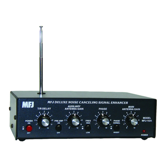
Page 5: Front Panel Controls
Front Panel Controls The MFJ-1026 has several user controls on the front panel. From left to right, the front panel controls are: POWER ON/OFF: This switch turns the main power off and on. In the OFF (out) position, the MFJ- 1026 is bypassed. -
Page 6: Jumper Settings
MFJ-1026 Instruction Manual Deluxe Noise Canceling Signal Enhancer T/R DELAY: This control adjusts the recovery time of the internal bypass relay. Never set this control for QSK CW operation, always make sure the relay stays closed (you shouldn't be able to hear it click) during a string of dots. - Page 7 MFJ-1026 Instruction Manual Deluxe Noise Canceling Signal Enhancer Note: MFJ supplies one shorting clip with the MFJ-1026. This shorting clip is the only one needed for all configurations. When using the internal noise antenna: If JMP1 is installed, sensitivity of the internal whip antenna will decrease greatly even if the external noise antenna is disconnected.
- Page 8 Many modern transceivers have an EXTERNAL PTT output pin on one of the radio accessory ports. This can be used to pull the T/R Control line LOW, so the MFJ-1026 is put safely into the transmit mode, before any signal is transmitted.
-
Page 9: Power Supply
MFJ-1026 on the output of either an amplifier or antenna tuner! NEVER install the MFJ-1026 after an antenna tuner or an amplifier, due to the RF power and voltage handling limits of the unit. The RF power handling limit of the MFJ-1026 is approximately 100 watts. - Page 10 Use with Beverage or Other Low Noise Antennas The MFJ-1026 can be used to enhance reception on 160 and 80 meters, even if the station already employs low noise directional receiving arrays. If the receiving antennas connect to the receiver through a special receiving antenna input connection (a receive antenna jack), the MFJ-1026 should be inserted in that lead.
-
Page 11: Grounding Considerations
Grounding Considerations Connect the MFJ-1026 to the station ground buss with a short ground connection. Always use a good station ground connection to reduce the risk of lightning damage to station equipment, improve performance, and to improve operator safety. -
Page 12: Operation
Adjust the MAIN ANTENNA GAIN control fully clockwise. Tune in a strong steady signal. Turn the MFJ-1026 power switch on. The red LED should light and you should hear the internal relay click. You should still hear the same signal. Look at the receiver's S meter and remember the signal strength. -
Page 13: Other Applications
MFJ-1026 Instruction Manual Deluxe Noise Canceling Signal Enhancer 12. Try peaking a signal. The strongest peak will usually be very near the setting of the PHASE control that produces the deepest null for the same signal, but the PHASE switch will be in the opposite position from the null position. -
Page 14: Technical Assistance
If you have any problem with this unit first check the appropriate section of this manual. If the manual does not reference your problem or your problem is not solved by reading the manual, you may call MFJ Technical Service at 601-323-0549 or the MFJ Factory at 601-323-5869. You will be best helped if you have your unit, manual and all information on your station handy so you can answer any questions the technicians may ask. - Page 15 MFJ-1026 Instruction Manual Deluxe Noise Canceling Signal Enhancer Schematic...
- Page 16 MFJ-1026 Instruction Manual Deluxe Noise Canceling Signal Enhancer Settings Log use this log to record settings AUXILIARY Main AUXILIARY MAIN Freq Direction Phase Antenna Antenna gain gain...
Need help?
Do you have a question about the MFJ-1026 and is the answer not in the manual?
Questions and answers