Olivetti ECR 7100 Service Manual
Hide thumbs
Also See for ECR 7100:
- Brugervejledning (31 pages) ,
- Guia do utilizador (31 pages) ,
- User manual (31 pages)
Table of Contents
Advertisement
Advertisement
Table of Contents

Related Manuals for Olivetti ECR 7100


Summary of Contents for Olivetti ECR 7100
- Page 1 Cash Register ECR 7100 SERVICE MANUAL Code Y 110910 - 8...
- Page 2 Gruppo Telecom Italia B.U. Service & Caring Solutions Via Montenavale 1 - 10015 Ivrea (ITALY) www.olivetti.com Copyright© 2009, Olivetti All rights reserved CAUTION Danger of explosion if the battery is not replaced properly. Replace only with same or equivalent type recommended by the manufacturer.
-
Page 3: Table Of Contents
__________________________________________________________________________________________ CONTENTS MAJOR FEATURES……………………………………………………………………………………… 6 ECR7100 EXERNAL COMPONENTS……………………………………………………………………….. 7 CASH REGISTER SPECIFICATIONS……………………………………………………………………….. 8 SAFETY PRECAUTIONS……………………………………………………………………………………… 9 MAINTAINING THE CASH REGISTER……………………………………………………………………… 9 UNPACKING AND SETTING UP THE CASH REGISTER……………………………………………….. 10 STANDARD ACCESSORIES………………………………………………………………………………… 10 PRINTR COMPARTMENT……………………………………………………………………………………. 11 1. PRODUCT OUTLINE…………………………………………………………………………………. 14 HARDWARE……………………………………………………………………………….. 14 DISPLAY……………………………………………………………………………………... - Page 4 _________________________________________________________________________________________ 4. CIRCUITRY……………………………………………………………………………………………….41 POWER SUPPLY CIRCUIT………………………………………………………………...41 TRANSFORMER WIRIN DIAGRAM………………………………………………………43 POWER SUPPLY SPECIFICATION………………………………………………………44 C37560MFA MICROCOMPUTER…………………………………………………………45 RESET CIRCUIT…………………………………………………………………………….49 POWER FAIL CIRCUIT…………………………………………………………………….50 DISPLAY CIRCUIT………………………………………………………………………….51 DISPLAY TUBE INFORMATION………………………………………………………….51 KEYBOARD CIRCUIT……………………………………………………………………...52 4-10 DRAWER CIRCUIT…………………………………………………………………………54 4-11 BUZZER CIRCUIT………………………………………………………………………….54 4-12 BATTERY CIRCUIT……………………………………………………………………..55 4-13 MEMORY…………………………………………………………………………………….56 4-14 PRINTER CIRCUIT………………………………………………………………………….57 5.
- Page 5 __________________________________________________________________________________________ PREFACE This Service Manual is addressed to the field engineers who will install and service the cash register. it also provides product maintenance guidelines. SUMMARY This manual Is divided into five chapters. The first two chapters describe the operating, functional checks and maintenance procedures. Chapter 3 describes the disassembly and reassembly procedures, Chapter 4 gives troubleshooting/repair information while Chapter 5 describes the electronic circuitry.
-
Page 6: Major Features
_________________________________________________________________________________________ MAJOR FEATURES • 14 departments and up to 200 Price Look-Up (PLU) settings; • 8 clerk numbers to monitor the sales of individual employees; • 9-digit operator numeric Liquid Crystal Display (LCD); • Quantity entries using the decimal point; •... -
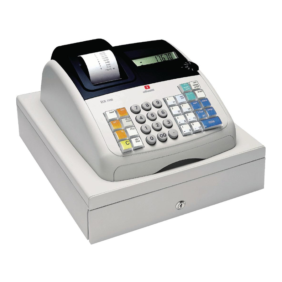
Page 7: Ecr7100 Exernal Components
__________________________________________________________________________________________ ECR 7100 EXTERNAL COMPONENTS With reference to figure: 1. Operator Display 2. Keypad 3. Cash Drawer 4. Cash Drawer 5. Power Cord 6. Customer Receipt Output Window 7. Printer Compartment Cover 8. Control Dial Y110930 – 8 ECR7100 Service Manual... -
Page 8: Cash Register Specifications
_________________________________________________________________________________________ CASH REGISTER SPECIFICATIONS ECR 7100 Technical Characteristics Listed below are the technical characteristics of this cash register model. Type: Electronic cash register with printer, 14 departments, 8 clerks, up to 200 PLU settings Display: 9-digit operator LCD. Symbols for error, change, subtotal, minus,... -
Page 9: Safety Precautions
__________________________________________________________________________________________ SAFETY PRECAUTIONS The power socket for this cash register must be located near the machine and must be easily Accessible. Do not use this cash register outdoors in the ram or near any liquid. MAINTAINING THE CASH REGISTER Provided below is information on how to maintain the cash register. Before cleaning the cash register, make sure it Is powered off and/or unplugged Note: from the wall outlet. -
Page 10: Unpacking And Setting Up The Cash Register
_________________________________________________________________________________________ UNPACKING AND SETTING UP THE CASH REGISTER STANDARD ACCESSORIES The cash register comes with the following items: • One black plastic journal winder spindle • One roll of standard paper tape • Three standard ‘AN’ size batteries for the battery back-up system •... -
Page 11: Printr Compartment
This cash register uses standard 21/4” (57 mm) thermal paper. LOADING THERMAL PAPER FOR ECR 7100 Proceed as follows to Ioad the cash register with paper. 1. Make sure the cash register is plugged into a grounded power outlet. - Page 12 _________________________________________________________________________________________ 6. Lower the clamshell mechanism and secure it in place by pushing it all the way down until it clicks into pace. Replace journal winder with wheel to right of compartment. Pass the edge of the customer receipt through the receipt window on the compartment cover.
- Page 13 __________________________________________________________________________________________ Note: I the paper does not feed properly, check the alignment of the paper in the slot and/or for the straight edge on the end on the paper roll. 11. Il you are loading a journal record, slide edge of tape through slots on journal winder spindle (depress the [Feed] key to advance additional tape, if necessary).
-
Page 14: Product Outline
_________________________________________________________________________________________ 1. PRODUCT OUTLINE 1-1 HARDWARE The terminal uses a 8-bits single chip microcomputer. The CPU has 60K bytes of internal ROM and 2K bytes of internal RAM, and uses 256K bytes S-RAM of external memory. This terminal uses 9-digits LCD. This terminal also has a battery -backed up clock that keeps tracks of the month, day of the week, date, hour and minute. -
Page 15: The Keypad Ecr7100
__________________________________________________________________________________________ 1-4 THE KEYPAD FOR ECR 7100 The figure below shows the keypad layout 1-5 KEYPAD FUNCTIONS The keys described here are those configured by default on the cash register keyboard, shown in figure 5. The symbol (*) indicates that the key is also used in caption programming. - Page 16 _________________________________________________________________________________________ sale; for example, the start-up money put in the drawer at the start of each business day can be registered as an RA. As the Currency Conversion key, it is used to automatically calculate and display the value in foreign currency of the subtotal of a sale or of a particular amount registered. 5.
- Page 17 __________________________________________________________________________________________ 14. - Multiplies [DEPARTMENT], entries and displays the current time in the REG and JRNL modes. 15. - Clears an entry made from the numeric keypad or with before finalizing a before transaction with a Department or function key. Also used to clear error conditions . 16.
-
Page 18: Drawer
_________________________________________________________________________________________ 1-6 DRAWER The drawer type is DSSA, 3 Bill / 8 Coin with D/DRAWER . 1-7 PRINTER The printer is EPSON M-42V, that is a character wheel type serial printer. 57.5mm (+/- 0.5mm) 1 Station. ECR7100 Service Manual Y110910 - 8... -
Page 19: System Block Diagram
__________________________________________________________________________________________ 1-8 SYSTEM BLOCK DIAGRAM 9.83MHz 32.768KHz Clock Clock Motor/ Segment ET6621S Winding Main CPU Front Display Solenoid Motor TMP86FS28DFG Com0,1,2 9digits display Control Printer Unit Timing Pulse Reset Pul e M42V Key Scan Keyboard Key Return Buzzer A0- A14 D0- D7 S - RAM Drawer... -
Page 20: Diagnostic Software
_________________________________________________________________________________________ 2. DIAGNOSTIC SOFTWARE 2-1. DIAGNOSTIC CHECK & FINISHED GOODS CHECK Diagnostic Software will check whether the machine works properly or not. It is already built in the machine and is always ready to boot this software by the following instructions. It is also useful to check after repairing the machine. -
Page 21: Diagnostic Check & Finished Goods Check
__________________________________________________________________________________________ It means OK when no error occurs through the checkup. _____________________________________________________________________________ Y110910 – 8 ECR7100 Service Manual... - Page 22 _________________________________________________________________________________________ FINISHED GOODS CHECK LIST ECR7100 Service Manual Y110910 - 8...
- Page 23 __________________________________________________________________________________________ _____________________________________________________________________________ Y110910 – 8 ECR7100 Service Manual...
-
Page 24: Software Version Check
_________________________________________________________________________________________ 2-2. SOFTWARE VERSION CHECK Through the diagnostic check, it shows the software version in the beginning of the check. However, it is possible to check only the software version without diagnostic check. SOFTWARE VERSION CHECK 1) Input [960801] at PRG mode position. 2) VFD will show you the current software version ECR7100 Service Manual Y110910 - 8... -
Page 25: Assembly Instruction
__________________________________________________________________________________________ 3. ASSEMBLY INSTRUCTION 3-1. TOP CASE UNIT APPLY SILICON OIL TO 1X2 KEY HOLE ONLY. FIX 25PCS BASE TOP TO KEY F RAME. FIX KEY TOP SHEET TO KEY CA P THEN FIX ON BASE TOP KEY. PUT RUBBER SHEET TO KEY FRAME WITH FLAT. - Page 26 _________________________________________________________________________________________ FIX K/B PWB UNIT TO KEY FRAME BY FASTEN 11PCS SCREW. FIX SLIDE CONTACT TO THE JOG DIAL CYCLINDER THEN MELT 1 POINT. (AS SHOWN AS ON PICTURE) ECR7100 Service Manual Y110910 - 8...
- Page 27 __________________________________________________________________________________________ FIX LCD COVER TO TOP CASE. MELT 2 RIBS TO TOP CASE. (LOCATION AS SHOWN ON PICTURE.) MELT LCD COVER RIB TO TOP CASE.(7 POINT) (FOLLOW THE PICTURE AS SHOWN ON FIGURE.) (10) APPLY GLUE 5 LEG LCD COVER TO TOP CASE.
- Page 28 _________________________________________________________________________________________ (11) FIX LCD WINDOW TO FRONT FILTER THEN MELT. STICK PEEL TAPE AT LCD WINDOW. (AS SHOWN AS ON PICTURE) ECR7100 Service Manual Y110910 - 8...
- Page 29 __________________________________________________________________________________________ ((12) FIX JOG DIAL CYCLINDER ASSY TO TOP CASE. (FOLLOW THE PICTURE AS SHOWN ON FIGURE) (13) FIX JOG DIAL CAP TO JOG DIAL CYCLINDER. (FOLLOW THE PICTURE AS SHOWN ON FIGURE) (14) FIX DIAL SW PWB TO TOP CASE THEN SCREW BY USE 2PCS SCREW.
- Page 30 _________________________________________________________________________________________ (15) FIX KB FRAME TO TOP CASE. (AS SHOWN AS ON PICTURE) (16) INSERT DIAL SW CONNECTOR TO KB PWB. (17) FIX MAIN BOARD PCB TO TOP CASE BY FASTEN 4PCS SCREW. (AS SHOWN AS ON PICTURE) ECR7100 Service Manual Y110910 - 8...
- Page 31 __________________________________________________________________________________________ (18) FIX PRINTER HEAD TO TOP CASE BY USE 2PCS SCREW AND 1PC WASHER. (AS SHOWN AS ON PICTURE) (19) INSERT PRINTER JOINER TO PRINTER PCB. (AS SHOWN AS ON PICTURE) (20) FASTEN 1PCS SCREW TO PRINTER PCB TO TOP CASE. _____________________________________________________________________________ Y110910 –...
- Page 32 _________________________________________________________________________________________ (21) FIX MOTOR SET PIECE TO TOP CASE. (22) FIX MOTOR UNIT TO SET PIECE THEN TURN ROUND & PRESS UNTIL IT IS LOCKED. (23) FIX 2PCS BATTERY CONTACT TO TOP CASE. (AS SHOWN AS ON PICTURE) ECR7100 Service Manual Y110910 - 8...
- Page 33 __________________________________________________________________________________________ (24) SLOT BATTERY CONTACT (+/-) TO TOP CASE. THE BATTERY CONTACT SHOULD BE PRESSED UNTIL IT IS LOCKED. (25) BAND BATTERY CONTACT (+) TO 90°AFTER INSERT. (AS SHOWN AS ON PICTURE) (26) STICK FILAMENT TAPE, HARNESS TO TOP CASE. (AS SHOWN AS ON PICTURE) (27) INSERT KB JUMPER LEAD TO...
- Page 34 _________________________________________________________________________________________ (29) FIX FRONT SET PIECE TO TOP CASE BY FASTEN 5PCS SCREW. (AS SHOWN AS ON PICTURE) (30) TOP CABINET ASS’Y IS COMPLETED. ECR7100 Service Manual Y110910 - 8...
-
Page 35: Drawer Unit Assy
__________________________________________________________________________________________ 3-2. DRAWER unit ASSY DRAWER ASSEMBLY. FIX TRANSFORMER ASS’Y AT DRAWER ASSEMBLY BY USE 2PCS SCREW. _____________________________________________________________________________ Y110910 – 8 ECR7100 Service Manual... - Page 36 _________________________________________________________________________________________ FIX CORD STOPPER TO AC CORD THEN FIX AT UPPER PLATE BY FASTEN 2PCS SCREW. (FOLLOW THE PICTURE AS SHOWN ON FIGURE) TIE UP THE AC CORD WIRE AND DRAWER HARNESS BY USE INSULOCK TIE. (FOLLOW THE PICTURE AS SHOWN ON FIGURE) ECR7100 Service Manual Y110910 - 8...
- Page 37 __________________________________________________________________________________________ FIX PRINTER HARNESS TO DRAWER BY FASTEN 1PC SCREW AND USE GEAR WASHER UNDER THE SCREW. (AS SHOWN AS ON PICTURE) INSERT DRAWER AND TRANSFORMER CABLE TO MAIN PCB. _____________________________________________________________________________ Y110910 – 8 ECR7100 Service Manual...
- Page 38 _________________________________________________________________________________________ ASSY THE TOP CASE TO DRAWER UNIT. (AFTER FIX MUST BE CHECK THE ARROW DIRECTION) FASTEN 1PC SCREW TOP CABINET TO UPPER PLATE. (AS SHOWN AS ON PICTURE) ECR7100 Service Manual Y110910 - 8...
- Page 39 __________________________________________________________________________________________ FIX WRITING TABLE TO TOP CASE. (AS SHOWN ON PICUTRE.) (10) FIX DEPOSIT DRAWER TO ASSY SET. _____________________________________________________________________________ Y110910 – 8 ECR7100 Service Manual...
- Page 40 _________________________________________________________________________________________ (11) SETTING BATTERY AND WINDING REEL TO ASSY UNIT. (12) ASSY’S COMPLETED. CHECK THE SOFTWARE BY DIAGNOSTIC SOFTWARE CHECK. (REFER TO SECTION 3. DIAGNOSTIC SOFTWARE) ECR7100 Service Manual Y110910 - 8...
-
Page 41: Circuitry
__________________________________________________________________________________________ 4. CIRCUITRY 4-1 POWER SUPPLY CIRCUIT +18V +18V is generated using the 15.6V AC input across Pins 1 and 2 of CN1. This AC voltage is rectified by the bridge rectifier and filtered by EC6, a 4700μF capacitor. The resulting DC voltage is about +18V. +P6V The circuit generating the +6V uses the +18V. - Page 42 _________________________________________________________________________________________ POWER SUPPLY CIRCUIT continued D 4 R L102-E R L102-E R L102-E D2 R L102-E EC 6 4700uF_35V C 10 0.1uF ZD3 H Z7A 3TA-E 47uF_25V ECR7100 Service Manual Y110910 - 8...
-
Page 43: Transformer Wirin Diagram
__________________________________________________________________________________________ 4-2 TRANSFORMER WIRING DIAGRAM AC230V 50Hz Powertrans._CT-81E _____________________________________________________________________________ Y110910 – 8 ECR7100 Service Manual... -
Page 44: Power Supply Specification
_________________________________________________________________________________________ 4-3 POWER SUPPLY SPECIFICATION Input-Power Consumption Standing by : Maximum 5.5watts Printing : Maximum 16 watts Output-Rated Voltage Voltage : 5.3V± 0.25V Standing by -5V to GND Ripple : Less than 0.4V p-p Printing Stability : Line regulation-less than 0.3V Viac. -
Page 45: C37560Mfa Microcomputer
__________________________________________________________________________________________ 4-4 TMP86FS28DFG MICROCOMPUTER Description The TMP86FS28DFG is a single-chip microcomputer designed with CMOS silicon gate technology. In addition to its simple instruction sets, the ROM, RAM and I/O addresses are placed on the same memory map to enable easy programming. PIN Configuration _____________________________________________________________________________ Y110910 –... - Page 46 _________________________________________________________________________________________ Function of TMP86FS28DFG Number of basic instructions Instruction execution time 0.25us (minimum instructions, at 16MHz of frequency) Clock frequency 16MHz(max.) Memory size 2.0K bytes Input / Output port P00-02 3-bit×1 P10-17 8-bit×1 P20-22 3-bit×1 P30-37 8-bit×1 P40-47 8-bit×1 P50-57 8-bit×1 P60-67 8-bitX1...
- Page 47 __________________________________________________________________________________________ Port assigns (TMP86FS28DFG) Port # Pin Specification Signal Signal INITIAL Remark Port Assignment Specification (Backup) Pin Name Type Name Term. Data Data Summary (Common) Printer Control P_MOTOR PRINTER MOTOR GND-PD P_TRG PRINTER TORIGER GND-PD GND-PD INT3/PPG10 TP-t Timing Plus t Key scan AIN0 Key Scan...
- Page 48 _________________________________________________________________________________________ Key return VCC-PU SEG31/TXD0 Key Return GND-PD Drawer SEG30/RXD0 DRAWER DRAWER ON Assigning PWM for Winding reel SEG29/TC3/PDO3/ winding WIND_ON Winding Motor On GND-PD motor control PWM3 noise. Port assigns(TMP86FS28DFG) continued SEG28/TC4/PDO4/ SRAM for PLU (*3) PWM4/PPG4 SRAM CE SEG27/TC5/PDO5/ CPU control line (*3)...
-
Page 49: Reset Circuit
__________________________________________________________________________________________ P-ON:+5V/ Power VAREF BackUp:+5.5V_1.8V Power Ground(0V) AVSS COM3 COM2 COM1 COM0 4-5 RESET CIRCUIT The reset circuit prevents the CPU from starting to operate before the system is fully powered-up and initialized. Then 2us after power is applied, reset goes high and the CPU can begin functioning. When power in first applied to the circuit, the VBB begins charging EC7, a capacitor. -
Page 50: Power Fail Circuit
_________________________________________________________________________________________ 4-6 POWER FAIL CIRCUIT A circuit using point the Collector of transistor Q3 generates power fail. When power is ON and system is operating normally, the power fail signal stays at a high level 10uF_16V 1N4148 2SC3242 1N4148 1N4148 3.3K 4.7K HZ5B1... -
Page 51: Display Circuit
__________________________________________________________________________________________ 4-7 DISPLAY CIRCUIT Display is controlled by CPU. Control signals are Com0, Com1, Com2 and Seg.0-25, 32, 33. LCD is 1/3 duty 1/2 Bias. 4-8 DISPLAY TUBE INFORMATION Display Digit . . . . . . . . . G1,G11,G12 Not used Display specification Display;... -
Page 52: Keyboard Circuit
_________________________________________________________________________________________ 4-9 KEYBOARD CIRCUIT Keyboard scan is performed by CPU interrupt routine. P10 through P17 are commonly used with scan signal. P43 through P47 are return line of Keyboard Matrix. It is consist of matrix of Strobe line(8)×Return line(5) and total of 37 keys are assigned. In order to remove chattering, key entry is confirmed when two sequential entry of a key. - Page 53 __________________________________________________________________________________________ Key Layout _____________________________________________________________________________ Y110910 – 8 ECR7100 Service Manual...
-
Page 54: Drawer Circuit
_________________________________________________________________________________________ 4-10 DRAWER CIRCUIT The drawer is activated using the signal P51 from the CPU. This signal is normally Low, and goes High to cause the drawer to run. When P47 is High, Q5 is on. Current flows through the transistor cause the collector to be held Low, near ground potential. RL102-E B3P-SHF-1AA DRAWER_ON... -
Page 55: Battery Circuit
__________________________________________________________________________________________ 4-12 BATTERY CIRCUIT When the +18V supply starts dropping, as in a power fail condition, the voltage through the divider network drops accordingly. When +18V no voltage, Q3 and D8 are shut off current VBB is through the D9 from battery. When the voltage at +18V has dropped, voltage back-up is provided by the battery. -
Page 56: Memory
_________________________________________________________________________________________ 4-13 MEMORY Memory uses BS62LV256 RAM (Random Access Memory) chips. The RAM chips are addressed directly by the CPU. PIN configuration / WE / OE BS62LV256SC / CE Pin Name Address Input A0-A14 Chip Enable Write Enable Output Enable DQ0-7 Data Input/output Power... -
Page 57: Printer Circuit
__________________________________________________________________________________________ 4-14 PRINTER CIRCUIT Printer Motor The printer motor is activated using the signal P00 from the CPU. This signal is normally Low, and goes High to cause the motor to run. Printer Magnets The signal P01 from the CPU is the input for the printer magnets. These normally low signals drop high with a print signal Timing Signal The printer generates, through the use of a mechanical switch assembly, a timing signal that is... -
Page 58: Curcuit Digram
_________________________________________________________________________________________ 5. CURCUIT DIAGRAM RL102-E DRAWER B3P-SHF-1AA KPT-GT1720-5V 4.7K 4.7K 2SD986 JUMPER *JUMPER 4.7K 2SC1815 47Kx8 WIND MOTOR 33_1W B3B-XH-A JUMPER KEY BOARD1 0.1uF JUMPER JUMPER JUMPER JUMPER 0.1uF JUMPER JUMPER JUMPER LB1268-E 0.01uF 52147-1510 P_TRG OUT3 P_MOTOR OUT2 WIND_ON OUT1 100pFx8 PRINTER... - Page 59 CURCUIT DIAGRAM continued LCD1 (FRONT) SDT-C337-RP-0 SEG[0..30] SEG7 SEG8 SEG7 SEG8 SEG6 SEG9 SEG6 SEG9 SEG5 SEG10 COM[0..2] SEG5 SEG10 SEG4 SEG11 SEG4 SEG11 SEG3 SEG12 SEG3 SEG12 SEG2 SEG13 SEG2 SEG13 SEG1 SEG14 SEG1 SEG14 SEG15 SEG0 SEG0 SEG15 SEG16 DSP_CS SEG16...
- Page 60 _________________________________________________________________________________________ CIRCUIT DIAGRAM continued Dial Switch Board MDRTN SCAN0 SCAN1 REG1 SCAN2 SCAN3 REG2 SCAN4 SCAN5 2mm Pitch Board-in 2mm Pitch Board-in SCAN0 SCAN1 SCAN2 SCAN3 SCAN4 SCAN5 SCAN6 SCAN7 RETURN0 Diode Direction RETURN1 RETURN2 RETURN3 RETURN4 D1-D9 D1-D9 RETURN5 MDRTN 1N4148 1N4148...
-
Page 61: Exploded Diagram
6. EXPLODED DIAGRAM _____________________________________________________________________________ ECR7100 Service Manual Y110910 - 8...
Need help?
Do you have a question about the ECR 7100 and is the answer not in the manual?
Questions and answers