
Summary of Contents for SEDEMAC GC1100
- Page 1 ABSTRACT This manual is intended as an information guide for operating SEDEMAC's GC1100 genset controller. MANUAL FOR Doc #SED-MAN-GC1100-002 GC1100: Date: 20-Apr-2018 GENSET CONTROLLER Product Manual Version #0.00...
- Page 2 SEDEMAC Mechatronics Pvt. Ltd. reserves the right to change the contents of this document without prior notice. For permission requests and applications to reproduce any part of this publication should be addressed to SEDEMAC Mechatronics Pvt.
- Page 3 GC1100 SEDEMAC Safety Instructions General Instructions ✓ This document includes important instructions that should be followed during installation and maintenance of the generator Set controller. ✓ For safety reasons, the manufacturer recommends that this equipment be installed and serviced by an authorized service personnel.
- Page 4 GC1100 SEDEMAC ✓ Do not wear jewellery. Jewellery can cause a short circuit within electrical contacts and cause shock or burning. ✓ In case of an accident caused by electric shock, immediately shut down the electrical power source. If this is not possible, try to release the victim from the live conductor. Avoid direct contact with the victim.
- Page 5 GC1100 SEDEMAC List of Abbreviation This list contains the list of acronyms used in this document and it can be used to refer their respective description. This list does not contain units of measure. Acronym Description Alternating Current Acknowledge Alternator...
-
Page 6: Table Of Contents
GC1100 SEDEMAC Table of Contents Introduction .......................... 1 Key Highlights of the Product ..................1 Product Features ......................1 Specifications ........................3 Terminals ......................... 3 Power Supply Specifications ................... 4 Generator Voltages and Frequency Measurements ............4 Load Current Measurements................... 5 Mains Voltage and Frequency Measurements .............. - Page 7 GC1100 SEDEMAC RS485 MODBUS Based Protocol ..................43 Connection Details ..................... 43 Precautions ........................ 44 Function Code Used ....................44 Register Map ......................46 Protocol for CAN-Based Communication ................ 51 Connection Details ..................... 51 Structure of Communication ..................51 Packet Structure ......................58 Notes ............................
- Page 8 Figure 9: GC1100 genset controller from backside ..............12 Figure 10: GC1100 genset controller power circuit (used in the Auto Mains Failure Mode) ..14 Figure 11: GC1100 genset controller control circuit (used in the Auto Mains Failure mode) ..15 Figure 12: Control keys function ....................
- Page 9 Table 15: Sensor common point ....................8 Table 16: Communication ports ....................9 Table 17: Details of GC1100 terminals ..................12 Table 18: Screens of engine status and operating mode............16 Table 19: Control keys in different modes .................. 19 Table 20: Configurable parameters ....................
- Page 10 GC1100 SEDEMAC Table 33: Normal response from genset controller slave for Function 4 ........44 Table 34: Command from MODBUS master for Function 16 ............45 Table 35: Normal response from genset controller slave for Function 16 ........45 Table 36: Command from MODBUS master for Function 3 ............45 Table 37: Normal response from genset controller slave for Function 3 ........
-
Page 11: Introduction
This document elucidates information necessary for operating SEDEMAC's GC1100 genset controller. It empowers the user with the necessary information for using GC1100 genset controller in an application that involves communication of the genset controller with an external system similar as a server or a remote data communication system. -
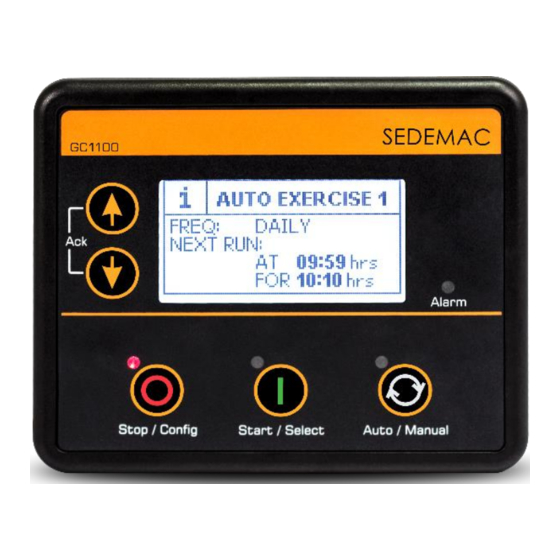
Page 12: Figure 1: Gc1100 Genset Controller's Front Fascia
Ingress Protection with Optional Gasket IP65 Sensor Common Input with ±2V Sensing Range Warning auto clear enable / disable Fuel reference selection input On the fly mode change when engine is healthy/engine off Figure 1: GC1100 genset controller's front fascia Page | 2... -
Page 13: Specifications
GC1100 SEDEMAC Specifications 2.1 Terminals GC1100 controller host three types of terminal blocks as shown in Figure Figure 3 Figure 4 given below: 10.16 mm pitch connector suitable for 2 sq. mm wire Figure 2: Connectors of 10.16 mm pitch Table 2: 10.16 mm pitch connector details... -
Page 14: Power Supply Specifications
GC1100 SEDEMAC Table 4: 3.5 mm pitch connector details Connector Male (On SM Part Female SM Part Quantity type controller) * Number (Mating)* Number (Nos) 4-Pin 5441294 SM0000278 5441430 SM0003731 5441317 SM0003346 5449283 SM0003732 6-Pin 5441320 SM0003348 5441456 SM0003733 8-Pin... -
Page 15: Load Current Measurements
GC1100 SEDEMAC For single genset application, it is mandatory to connect the genset phase and neutral cables to the genset controller's phase R and Neutral terminals respectively 2.4 Load Current Measurements Following table gives a brief overview of load current measurements... -
Page 16: Digital Inputs
GC1100 SEDEMAC 2.6 Digital Inputs Following table gives a brief overview of digital inputs Table 9: Digital inputs Controller's terminal number 10, 11, 12, 21, 22 Number of inputs Type Negative sensing (connect switch to ground.) Open circuit voltage – 1) V-DC... -
Page 17: Analog Current Input
GC1100 SEDEMAC 2.8 Analog Current Input Following table gives a brief overview of analog current input Table 11: Analog voltage/current input Controller's terminal number Type current sensing Range 4 to 20 mA Accuracy ±1.25% of full scale Resolution 0.1mA Magnetic Pick Up Input... -
Page 18: D+ Chg Alt
GC1100 SEDEMAC D+ CHG ALT 2.11 Following table gives a brief overview of D+ CHG ALT Table 14: D+ CHG ALT Controller's terminal number Voltage range 0 to V = 8 to 30 V-DC BATT BATT PWM (Current limited to 250 mA Or Average Power should be... -
Page 19: Communication Ports
GC1100 SEDEMAC Communication Ports Following table gives a brief overview of communication ports Table 16: Communication ports USB 2.0 Type B used for connection to PC running SEDEMAC Smart config. Half Duplex Max Baud Rate 115200 Data connection 2 wire RS485 Serial Port Termination resistor of 120Ω... -
Page 20: Installation
SEDEMAC Installation 4.1 Dimensions Figure 6: Dimensions of the GC1100 genset controller Recommended mounting panel cut-out dimensions: 118 mm X 93 mm. 4.2 Mounting on panel To mount the controller into the panel, use the fixing clips provided along with the controller. -
Page 21: Figure 7: Fixing Clip And Screw Supplied Along With Controller
GC1100 SEDEMAC Figure 7: Fixing clip and screw supplied along with controller Figure 8: Controller mounting on the panel using the fixing clips • Insert the fixing clip into the slot provided on the side of the controller. • Pull the fixing clips backwards (towards the back of the module). Ensure that the fixing clip is properly fitted inside the slot provided on the controller. -
Page 22: Terminal Description
GC1100 SEDEMAC 4.3 Terminal Description Following figure shows the rear view of controller. Figure 9: GC1100 genset controller from backside Table 17: Details of GC1100 terminals Phoenix Female Terminal Name Description (Mating) Connector Sr. No. Part No. Power Supply Ground... - Page 23 Sensor Common Point MPU–IN MPU Input * the 0-5V (2.5 ± 2V) input for paralleling is not available for the GC1100 variant, as it does not have e-governing module, which is shown in the print of the back casing. Page | 13...
-
Page 24: Typical Wiring Diagram
SEDEMAC 4.4 Typical Wiring Diagram Auto Mains Failure Application The typical wiring diagram of GC1100 for Auto Mains Failure application on engine with mechanical fuel system: Figure 10: GC1100 genset controller power circuit (used in the Auto Mains Failure Mode) -
Page 25: Figure 11: Gc1100 Genset Controller Control Circuit (Used In The Auto Mains Failure Mode)
GC1100 SEDEMAC Figure 11: GC1100 genset controller control circuit (used in the Auto Mains Failure mode) Page | 15... -
Page 26: Module Display
GC1100 SEDEMAC 1) Genset & mains contactor latching relays should be compiled against 4kV surge as per IEC-61000-4-5 standard. 2) Wiring drawing is for representation purpose only. Please refer wiring as per given genset application drawing. 3) Relay cards that used with controller should have protection against reverse battery voltages. - Page 27 GC1100 SEDEMAC LOAD REACTIVE POWER GENERATOR POWER FACTOR (The “Y” and “B” phase will be visible only if (The “PF-Y” and “PF-B” will be visible only if configured for 3 phase genset) configured for 3 phase genset) LOAD CURRENT GEN ENERGY (The “Y”...
- Page 28 GC1100 SEDEMAC BALANCE FUEL AUTO EXERCISE 1 (This screen will be visible only if “Event 1” is (This screen will be visible only if “Fuel Level” enabled from “Auto Exercise 1” in controller's sensor is configured) configuration) AUTO EXERCISE 2 CONTACTOR STATUS (This screen will be visible only if “Event 2”...
-
Page 29: Description Of Control Keys
GC1100 SEDEMAC Description of Control keys Figure 12: Control keys function 1. Menu Navigation Up key 2. Menu Navigation Down key 3. Stop/Config Key 4. Start/Select Key 5. Auto/Manual mode selection key 6.1 Functions of Control keys Following table gives a brief overview of different functions of control keys... -
Page 30: Configuration Mode
GC1100 SEDEMAC Mode Key input Function Event log Up + Down (long pressed) Back to configuration mode Programming Up + Down (long pressed) Controller enters in Manual mode Configuration Mode To configure the controller please follow the below mentioned instructions: •... -
Page 31: List Of Configurable Parameters
SEDEMAC 7.1 List of Configurable Parameters Following table gives a brief overview of configurable parameters in GC1100 controller * Level 2 names in sentence case are written how they display on Smart Config GUI and names in bracket with capital case are written how they display on controller. - Page 32 GC1100 SEDEMAC Level 1 (On Level 0 Level 2 (On screen) * Parameters (On screen) screen) Auto Exercise Disable/Enable (EVENT 2) Event Occurrence Daily/Weekly/Monthly (EVENT OCCURENCE) Event Day Runs Every day/Week Auto Exercise days/1 – 28 (EVENT DAY) Event 2...
- Page 33 GC1100 SEDEMAC Level 1 (On Level 0 Level 2 (On screen) * Parameters (On screen) screen) (ETS) High Level Warning Disable/Enable (WARNING) (ETS) High Level Warning Threshold 25 – 298 ̊ C (WARNING THRESHOLD) (ETS) Circuit Fault Action None/Notification/Warning /Electrical Trip/Shutdown...
- Page 34 GC1100 SEDEMAC Level 1 (On Level 0 Level 2 (On screen) * Parameters (On screen) screen) (LOP/DIG F) (SENSOR SELECTION) Anlg In LOP (Digital) Source Refer Table 21 ((DIG) SOURCE) (Digital) Polarity Close to Activate/Open to Activate ((DIG) POLARITY) (Digital) Action...
- Page 35 GC1100 SEDEMAC Level 1 (On Level 0 Level 2 (On screen) * Parameters (On screen) screen) (WARNING THRESHOLD) (LOP) Circuit Fault Action None/Notification/Warning/ Electrical Trip/Shutdown (OPEN CKT ACTION) (LOP) Lube Oil Pressure Sensor Refer Table 25 Calibration Table Source Refer...
- Page 36 GC1100 SEDEMAC Level 1 (On Level 0 Level 2 (On screen) * Parameters (On screen) screen) Alternator Present No/Yes (ALT PRESENT) Number of Poles 2/4/6/8 (NUMBER OF POLES) AC System 1 Phase/3 Phase (ALT AC SYSTEM) Min Healthy Voltage 50 – 350 Volt Ph-N...
- Page 37 GC1100 SEDEMAC Level 1 (On Level 0 Level 2 (On screen) * Parameters (On screen) screen) Over-frequency Shutdown Disable/Enable (OVER FREQ SHUTDOWN) Over-frequency Shutdown Threshold 26.0 – 75.0 Hz (OF SHUTDWN THRESHLD) Over-frequency Warning Disable/Enable (OVER FREQ WARNING) Over-frequency Warning Threshold 25.0 –...
- Page 38 GC1100 SEDEMAC Level 1 (On Level 0 Level 2 (On screen) * Parameters (On screen) screen) (PHASE REVERSE DETECT) Phase Reversal Action None/Notification (PHASE REVERSE ACTION) Partial Healthy Detection Disable/Enable (PARTL HLTHY DETECT) Enable No/Yes (ENABLE) Under-voltage Monitoring Trip 50 – 298 V Ph-N...
- Page 39 GC1100 SEDEMAC Level 1 (On Level 0 Level 2 (On screen) * Parameters (On screen) screen) (DISCONN ON LLOP SW) Pressure Switch Transient Time 0.0 – 3.0 sec (LLOP SW TRANS TIME) Crank Disconnect At Alt Frequency 10 – 70 Hz...
-
Page 40: Digital Input Sources Selection
GC1100 SEDEMAC Level 1 (On Level 0 Level 2 (On screen) * Parameters (On screen) screen) Monitoring Charging Alternator Fail (CHARGE ALT Threshold 0.0 – 35.0 V MON) (FAIL THRESHOLD) Charging Alternator Fail Delay 5 – 60 sec (FAIL DELAY) Preheat Timer 1 –... -
Page 41: Digital Output Source Selection
GC1100 SEDEMAC Water Level Switch (Low Water LVL Switch) Emergency Stop Remote Start / Stop Simulate Start Simulate Stop Simulate Auto Close Generator/Open Mains Switch (Close Gen/Opn Mains Swch) Close Mains/Open Generator Switch (Close Mains/Opn Gen Swch) Simulate Mains Reserved... - Page 42 GC1100 SEDEMAC Output source (On screen) Common Warning Cooling Down Digital Input A (Dig In A) Digital Input B (Dig In B) Digital Input C (Dig In C) Digital Input D (Dig In D) Digital Input E ((Dig In E)
-
Page 43: Module Operation
GC1100 SEDEMAC Output source (On screen) Manual Mode Preheat Output Module Operation There are two modes of operation • Auto Mode • Manual Mode 8.1 Auto Mode To enter Auto mode press “AUTO” key. The controller can be used in two configurations while in Auto mode. -
Page 44: Figure 16: Smd For Amf Mode
Auto Exercise Mode GC1100 controller allows to configure two scheduled sequences to start and stop the genset on preconfigured time. The Exercise will occur when the controller is in the Auto mode with no shutdown, electric trip or warning alarms. -
Page 45: Figure 17: Smd For Auto Exercise Mode
GC1100 SEDEMAC Figure 17: SMD for auto exercise mode • If the controller is in Auto mode, Exercise will run at scheduled time for pre-set DG ON DURATION. Controller will exit from Exercise mode, if the DG ON DURATION is expired or if Stop key is pressed while scheduled sequence is running. -
Page 46: Figure 18: Smd For Cyclic Mode
GC1100 SEDEMAC healthy and the warm up time is elapsed. After completion of the ON time, genset turns OFF taking cooling down time. Then controller will start DG off time. After completion of DG OFF time, DG ON time will start and this cycle will continue until mains is detected healthy. -
Page 47: Manual Mode
GC1100 SEDEMAC 8.2 Manual Mode Figure 19: SMD for manual mode Page | 37... -
Page 48: Alarms
SEDEMAC Alarms GC1100 controller allows to configure several Shutdown/Electrical trip, Warning and Notification alarms such as Low Oil Pressure Shutdown, Over Load Warning and many more. An alarm condition occurs when the preconfigured parameter is out of pre-set level. On initiation of an alarm, the Alarm LED will start blinking and Sounder alarm will be activated if configured. - Page 49 GC1100 SEDEMAC Alarms Causes Action options Notification Shutdown/ Indicates that radiator water level is below the pre-set Warning/ Low Water Level Switch threshold Electrical trip/ Notification Shutdown/ Auxiliary Warning/ Configured auxiliary input has triggered longer than pre- Input/user set duration...
- Page 50 GC1100 SEDEMAC Alarms Causes Action options Shutdown/ Indicates that genset output frequency has exceeded the Over Frequency pre-set threshold Warning Shutdown/ Indicates that genset output frequency has fallen below Under Frequency the pre-set threshold Warning Shutdown/ Indicates that genset current has exceeded the pre-set...
-
Page 51: Troubleshooting
GC1100 SEDEMAC Troubleshooting Table 29: Common faults and their remedial actions Sr. No. Faults Remedial Actions Possible Issues in MANUAL Mode The controller does not power • Check the battery voltage. • Check the fuse on the battery supply. •... - Page 52 GC1100 SEDEMAC Sr. No. Faults Remedial Actions RELAY” output polarity. The engine runs, but the • Check if the MPU signal (if used), and main alternator controller shows genset to be voltage signal (R phase) are received by the controller “OFF”.
-
Page 53: Introduction To Communication Protocol
SEDEMAC Communications Protocol Introduction to Communication Protocol GC1100 genset controller support two communication protocol: a custom protocol based on MODBUS over a RS485 layer and a custom protocol over a CAN layer. RS485 MODBUS Based Protocol GC1100 genset controller implement a custom protocol based on standard MODBUS protocol. It operates in a slave mode and responds to commands received from an external MODBUS master. -
Page 54: Precautions
Enable the GC1100 in the configuration of the SMPS after hardware connections are made, so the SMPS can communicate with the GC1100. • Connect the Pin # 16 & 15 (A & B) of the GC1100 to the pin # A & B of the SMPS respectively and not with any other pin. •... -
Page 55: Table 34: Command From Modbus Master For Function 16
GC1100 SEDEMAC Byte Field Remarks two. 8-bit even number between 2 to 250 First register – high byte First register – low byte Last register – high byte Last register – low byte 3+2n/4+2n Error check CRC Function 16 (0x10): Write Holding Registers This function is used to issue certain commands to the controller. -
Page 56: Register Map
GC1100 SEDEMAC Byte Field Remarks First register address – high byte 16-bit register address, register address map is described in Table 38 First register address – low byte Number of registers to read – high byte Number of registers to read must be between 1 to 255 Number of registers to read –... - Page 57 GC1100 SEDEMAC Register Parameter Scale Factor Unit/Interpretation Bits/ Sign Address Mains L2-L3 voltage Unsigned Mains L3-L1 voltage Unsigned Mains R frequency Unsigned Mains Y frequency Unsigned Mains B frequency Unsigned Load L1 current Unsigned Load L2 current Unsigned Load L3 current...
- Page 58 GC1100 SEDEMAC Register Parameter Scale Factor Unit/Interpretation Bits/ Sign Address Mains run min Unsigned Alarm 1 Low oil pressure 13/16-16/16 High coolant temperature 9/16-12/16 Low fuel level 5/16-8/16 Water level switch 1/16-4/16 Alarm 2 Under speed 13/16-16/16 Over speed 9/16-12/16...
- Page 59 GC1100 SEDEMAC Register Parameter Scale Factor Unit/Interpretation Bits/ Sign Address Alarm 9 Auxiliary input e 13/16-16/16 Auxiliary input f 9/16-12/16 Auxiliary input g 5/16-8/16 Auxiliary input h 1/16-4/16 Alarm 10 Gen L1 phase low volt 13/16-16/16 Gen L1 phase high volt...
-
Page 60: Table 39: Register Map For Holding Registers
GC1100 SEDEMAC Register Parameter Scale Factor Unit/Interpretation Bits/ Sign Address Scheduler-110 Cyclic-111 DG operation mode 14-12/16 Auto-101 Manual-100 Load on Mains True (1) / False (0) 11/16 Load on DG True (1) / False (0) 10/16 Current DG status Running / stopped... -
Page 61: Protocol For Can-Based Communication
Unimplemented Protocol for CAN-Based Communication GC1100 genset controller implement a CAN-based protocol that can be used for reading the measurement values, status of alarms and derived computations (such as cumulative power), as well as for sending mode change and start-stop commands to the controller. Details of the communication protocol are as described below . - Page 62 GC1100 SEDEMAC Register Scale Page No. Value for GC1100 Unit Bits/ Sign Offset Factor Page 7 Load L1 current Unsigned Mains Y frequency Unsigned Mains B frequency Unsigned Page 8 Load L1 watts Unsigned Load L2 current Unsigned Load L3 current...
- Page 63 GC1100 SEDEMAC Register Scale Page No. Value for GC1100 Unit Bits/ Sign Offset Factor Low oil pressure E-0001/0001 13/16-16/16 W-0010/0010 S-0011/0011 High coolant temperature E-0001/0001 9/16-12/16 W-0010/0010 S-0011/0011 Radiator water level / low fuel E-0001/0001 5/16-8/16 level N-0101/0101 S-0011/0011 water level switch...
- Page 64 GC1100 SEDEMAC Register Scale Page No. Value for GC1100 Unit Bits/ Sign Offset Factor E-0100/0100 S-0011/0011 Emergency stop E-0001/0001 1/16-4/16 S-0011/0011 Alarm 5 Charge alternator failure E-0001/0001 13/16-16/16 N-0101/0101 W-0010/0010 E-0100/0100 S-0011/0011 Maintenance E-0001/0001 9/16-12/16 N-0101/0101 W-0010/0010 Reserved 1111 5/16-8/16...
- Page 65 GC1100 SEDEMAC Register Scale Page No. Value for GC1100 Unit Bits/ Sign Offset Factor Auxiliary input a E-0001/0001 13/16-16/16 N-0101/0101 W-0010/0010 E-0100/0100 S-0011/0011 Auxiliary input b E-0001/0001 9/16-12/16 N-0101/0101 W-0010/0010 E-0100/0100 S-0011/0011 Auxiliary input c E-0001/0001 5/16-8/16 N-0101/0101 W-0010/0010 E-0100/0100...
- Page 66 GC1100 SEDEMAC Register Scale Page No. Value for GC1100 Unit Bits/ Sign Offset Factor Gen L2 phase high volt E-0001/0001 1/16-4/16 W-0010/0010 S-0011/0011 Alarm 11 E-0001/0001 Gen L3 phase low volt 13/16-16/16 W-0010/0010 S-0011/0011 Gen L3 phase high volt E-0001/0001...
-
Page 67: Table 42: Structure Of Broadcasted Message
GC1100 SEDEMAC Register Scale Page No. Value for GC1100 Unit Bits/ Sign Offset Factor Digital output f 2/16 Unimplemented 1/16 DG Status GCU Mode Config (1) /Run (0) 16/16 Mains Healthy / unhealthy True (1) / False (0) 15/16 DG operation mode... -
Page 68: Packet Structure
GC1100 SEDEMAC Packet Structure 13.3 Table 44: Structure of command message received over CAN Command Description Command Parameter (each of 1 Bytes) Bits/ Sign 0x01 - Start DG Start-Stop 0x02 - Stop DG Unsigned command Command Status is updated in status register 0x01 - Toggle Current mode of operation between the Auto mode and the Manual mode. -
Page 69: Notes
GC1100 SEDEMAC Notes Page | 59... - Page 70 GC1100 SEDEMAC Disclaimer: Due to continuous development, the details provided in this document are subject to change without any prior notice. SEDEMAC Mechatronics Pvt Ltd Technical Centre C9-10, C Block, MIDC Bhosari Pune 411026, India Manufacturing Plant G-1, MIDC, Phase-III Chakan...
Need help?
Do you have a question about the GC1100 and is the answer not in the manual?
Questions and answers