Advertisement
Quick Links
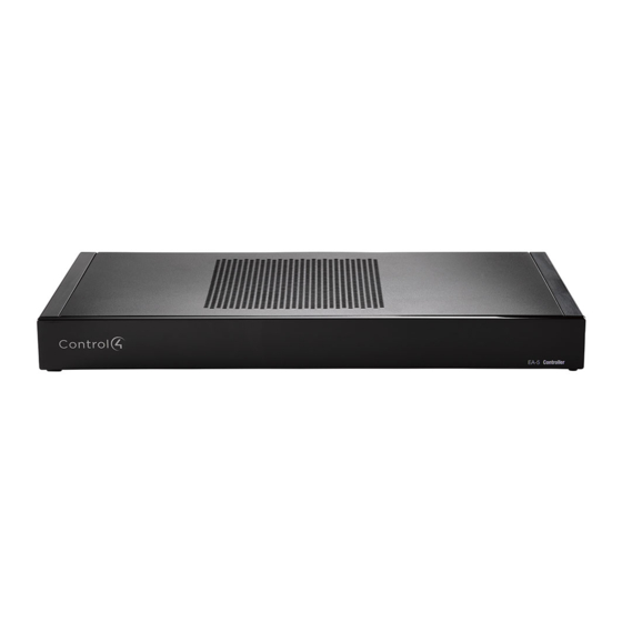
Control4 EA-5 Controller
Installation Guide
Supported model
• C4-EA5
Entertainment and Automation Controller, 5 Zone
• C4-EA5-V2
Entertainment and Automation Controller, 5 Zone, V2
Introduction
The Control4 EA-5 Entertainment and Automation Controller is
designed to deliver the ultimate smart home experience, featuring
the highest-quality audio of the EA series and processing power
to coordinate hundreds of smart devices. The EA-5 can automate
sophisticated home theaters, complex interior and exterior lighting
scenes, vital security and communications systems, and climate controls
for multiple zones.
The EA-5 features five independent audio outputs—two digital coaxial,
two RCA stereo analog, and one HDMI—with an audiophile-grade
signal-to-noise ratio of 118dB. A built-in music server delivers immersive,
multi-stream, high-resolution audio with five built-in simultaneous
audio streams from your local music collection, a variety of streaming
music services, or from AirPlay-enabled devices using native Control4
ShairBridge technology. Expand beyond five streams by including
additional EA-5 or EA-3 Controllers.
Secure, wireless ZigBee communication; plentiful I/O including IR, serial,
contacts and relays; and IP control enable connections to smart home
devices such as thermostats, door locks, doorbells, cameras, security
panels, sensors, lighting, shades, garage door controllers, irrigation
systems, and much more. The sleek design, rack-mount form factor, and
top-of-the-line connectivity make the EA-5 the ultimate foundation for
any Control4 system and the platform to power the future of your smart
home.
Box contents
The following items are included in the box:
• EA-5 controller
• AC power cord
• IR emitters (8)
• Rack ears (2, pre-installed on the EA-5 V2)
• Rubber feet (2, pre-installed on the EA-5 V1)
• External antennas (3 with EA-5 V1, 1 with EA-5 V2)
• Terminal blocks for contacts and relays
Accessories sold separately
• Control4 3.5 mm-to-DB9 Serial Cable (C4-CBL3.5-DB9B)
• Dual-Band WiFi USB Adapter for EA-5 V2 (C4-USBWIFI or C4-
USBWIFI-1)
Warnings
Caution! To reduce the risk of electrical shock, do not expose
this apparatus to rain or moisture.
Avertissement ! Pour réduire le risque de choc électrique,
n'exposez pas cet appareil à la pluie ou à l'humidité.
Caution! In an over-current condition on USB or contact
output the software disables the output. If the attached USB
device or contact sensor does not appear to power on, remove
the device from the controller.
Avertissement ! Dans une condition de surintensité sur USB ou
sortie de contact le logiciel désactive sortie. Si le périphérique
USB ou le capteur de contact connecté ne semble pas
s'allumer, retirez le périphérique du contrôleur.
Requirements and specifications
Note: We recommend using Ethernet instead of WiFi for the
best network connectivity.
Note: The Ethernet or WiFi network should be installed before
you install the EA-5 controller.
Note: The EA-5 V2 requires OS 2.10.2 or higher. The EA-5 V1
requires OS 2.8.1 or higher.
Composer Pro is required to configure this device. See the Composer
Pro User Guide (
ctrl4.co/cpro-ug
) for details.
Specifications
Inputs / Outputs
Video out
1 video out—1 HDMI
Video
HDMI 1.4 output; HD 1080p, 50-60 Hz
Audio out
5 audio out—1 HDMI, 2 stereo analog, 2 digital coax
Audio playback formats
AAC, AIFF, ALAC, FLAC, M4A, MP2, MP3, MP4/M4A,
Ogg Vorbis, PCM, WAV, WMA
High-res audio playback
Up to 192 kHz / 24 bit
Audio in
4 audio in—2 stereo analog, 2 digital coax
Audio delay on audio in
Up to 3.5 seconds, depending on network conditions
Advanced audio subsystem
Dual audio signal processors, multiple sample rate
converters
Audio system controls
10-band graphic equalizer, input gain, output gain,
(analog or digital coax)
loudness, tone controls, balance
Signal-to-noise ratio
<-118 dBFS
Total harmonic distortion
0.00023 (-110 dB)
Network
Ethernet
10/100/1000BaseT compatible (required for controller
setup).
Built-in Ethernet switch
1 Ethernet in + 4 gigabit Ethernet switch ports
WiFi
Internal Dual-Band Wireless-N (EA-5 V1)
(2.4GHz, 5GHz, 802.11n/g/b) (EA-5 V1)
Optional Dual-Band WiFi USB Adapter (EA-5 V2)
(2.4 GHz, 5 Ghz, 802.11ac/b/g/n/a)
WiFi security
WPA/WPA2
WiFi antenna
2 external reverse SMA connectors (EA-5 V1)
ZigBee Pro
802.15.4
ZigBee antenna
External reverse SMA connector
eSATA port
1 eSATA port
USB port
1 USB 2.0 port—500mA
Control
IR OUT
8 IR out—5V 27mA max output
1 IR blaster—front
IR capture
1 IR receiver—front; 20-60 KHz
SERIAL OUT
4 Serial out—2 DB9 ports and 2 shared with IR out 1-2
Contact
4 contact sensors—2V-30VDC input,
12VDC 0.5A maximum output
Relay
4 relays—AC: 36V, 2A maximum voltage across relay;
DC: 24V, 2A maximum voltage across relay
Power
Power requirements
100-240 VAC, 60/50Hz
Power consumption
Max: 40W, 136 BTUs/hour
Idle: 15W, 51 BTUs/hour
Other
Operating temperature
32˚F ~ 104˚F (0˚C ~ 40˚C)
Storage temperature
4˚F ~ 158˚F (-20˚C ~ 70˚C)
Fan dB level
Max: 35 dB
Dimensions (H × W × D)
17.5
×
10.125
×
1.875" w/feet (444
×
258
Weight
6.85 lbs (3.10 kg)
Shipping weight
9.30 lbs (4.20 kg)
Additional resources
The following resources are available for more support.
• Control4 Knowledgebase:
kb.control4.com
forums.control4.com
• Control4 Technical Support
• Control4 website:
www.control4.com
• Composer Pro documentation in online help or PDF format available
on the Dealer Portal under Support:
ctrl4.co/docs
Front view
A
B
1
2
3
4
ETHERNET IN
SERIAL 1
ID
A Data LED—The LED indicates that the controller is streaming audio.
AC POWER:
WIFI 1
WIFI 2
100-240 V~
FACTORY
GIGABIT SWITCH
USB
E-SATA
SERIAL 2
60/50 Hz, 0.5 A
RESET
B IR window—IR blaster and IR receiver for learning IR codes.
C Caution LED—This LED shows solid red, then blinks blue during the
boot process.
Note: The Caution LED flashes orange during the factory
restore process. See "Reset to factory settings" in this
document.
D Link LED—The blue LED indicates that the controller has been
identified in a Control4 Composer project and is communicating with
Director.
E Power LED—The blue LED indicates that AC power is connected. The
controller turns on immediately after power is applied to it.
Back view
ETHERNET IN
1
2
3
4
SERIAL 1
ID
AC POWER:
WIFI 1
WIFI 2
100-240 V~
SERIAL 2
FACTORY
60/50 Hz, 0.5 A
GIGABIT SWITCH
USB
E-SATA
RESET
A
B
C
D E F G H I
J K
A Power plug port—AC power receptacle for an IEC 60320-C13 power
cord.
B WIFI 1—Antenna 1 for the WiFi radio (EA-5 V1 only).
C Contact/Relay port—Connect up to four relay devices and four
contact sensor devices to the terminal block connector. Relay
connections are COM, NC (normally closed), and NO (normally
open). Contact sensor connections are +12, SIG (signal), and GND
(ground).
D GIGABIT SWITCH—Four-port gigabit ethernet switch to connect
other local devices to the network.
E ETHERNET IN—RJ-45 jack for a 10/100/1000 BaseT Ethernet
connection.
F USB—One port for an external USB drive or, on an EA-5 V2, the
optional Dual-Band WiFi USB Adapter. See "Set up external storage
devices" in this document.
G E-SATA—One port for an external eSATA drive. See "Setting up
external storage devices" in this document.
H WIFI 2—Antenna 2 for the WiFi radio (EA-5 V1 only)
I
SERIAL—Two serial ports for RS-232 control. See "Connecting the
serial ports" in this document.
J ID and FACTORY RESET—ID button to identify the device in
Composer Pro. The ID button on the EA-5 V2 is also an LED that
displays feedback useful during a factory restore. FACTORY RESET
button is used to restore the controller to factory defaults. Can also
reboot the controller.
K HDMI OUT—An HDMI port to display system menus. Also an audio
out over HDMI.
L IR / SERIAL—Eight 3.5 mm jacks for up to eight IR emitters or for
a combination of IR emitters and serial devices. Ports 1 and 2 can
be configured independently for serial control or for IR control. See
"Setting up IR emitters" in this document for more information.
M DIGITAL AUDIO—Two digital coax audio input and two output ports.
Allows audio to be shared (IN 1 or 2) over the local network to other
Control4 devices. Outputs audio (OUT 1 or 2) shared from other
×
49 mm)
Control4 devices or from digital audio sources (local media or digital
streaming services such as TuneIn.)
N ANALOG AUDIO—Two stereo audio input and two output ports.
Allows audio to be shared (IN 1 or 2) over the local network to other
Control4 devices. Outputs audio (OUT 1 or 2) shared from other
Control4 devices or from digital audio sources (local media or digital
streaming services such as TuneIn.)
O ZIGBEE—Antenna for the ZigBee radio.
Installing the controller
To install the controller:
and Dealer Forums:
1
Ensure that the home network is in place before starting system
setup. The controller requires a network connection, Ethernet
(recommended) or WiFi, to use all of the features as designed.
When connected, the controller can access web-based media
databases, communicate with other IP devices in the home, and
access Control4 system updates.
2 Mount the controller in a rack or stacked on a shelf. Always allow
plenty of ventilation. See "Mounting the controller in a rack" in this
document.
3 Connect the controller to the network.
• Ethernet—To connect using an Ethernet connection, plug
the data cable from the home network connection into the
C D E
1/ 3
3
5
7
IN 1
OUT 1
controller's RJ-45 port (labeled "ETHERNET IN") and the
OUT
network port on the wall or at the network switch.
2/ 4
4
6
8
IN 2
OUT 2
IN 1
IN 2
OUT 1
OUT 2
ZIGBEE
IR / SERIAL
DIGITAL AUDIO
ANALOG AUDIO
• WiFi—To connect using WiFi, first connect the controller to
Ethernet, and then use Composer Pro System Manager to
reconfigure the controller for WiFi.
Important: Do not install your EA controller on a
172.18.xxx.xxx subnet.
4 Connect system devices. Attach IR and serial devices as described
in "Connecting the IR ports/serial ports" and "Setting up IR
emitters."
5 Set up any external storage devices as described in "Setting up
external storage devices" in this document.
6 Power up the controller. Plug the power cord into the controller's
power plug port and then into an electrical outlet.
1/ 3
3
5
7
IN 1
OUT 1
Mounting the controller in a rack
OUT
2/ 4
4
6
8
IN 2
OUT 2
IN 1
IN 2
OUT 1
OUT 2
ZIGBEE
Using the pre-installed rack-mount ears, the EA-5 can easily be
IR / SERIAL
DIGITAL AUDIO
ANALOG AUDIO
mounted in a rack for convenient installation and flexible rack
L
M
N
O
placement. The pre-installed rack-mount ears can even be reversed to
mount the controller facing the rear of the rack, if needed.
To attach the rubber feet to the controller:
1
Remove the two screws in each of the rack ears on the bottom of
the controller. Remove the rack ears from the controller.
2 Remove the two additional screws from the controller case and
place the rubber feet on the controller. .
3 Secure the rubber feet to the controller with three screws in each
rubber foot.
Pluggable terminal block connectors
For the contact and relay ports, the EA-5 makes use of pluggable
terminal block connectors which are removable plastic parts that locks
in individual wires (included).
To connect a device to the pluggable terminal block:
1
Insert one of the wires required for your device into the appropriate
opening in the pluggable terminal block you reserved for that
device.
2 Use a small flat-blade screwdriver to tighten the screw and secure
the wire in the terminal block.
Example: To add a motion sensor (see Figure 3), connect its
wires to the following contact openings:
• Power input to +12V
• Output signal to SIG
• Ground connector to GND
Note: To connect dry contact closure devices, such as
doorbells, connect the switch between +12 (power) and SIG
(signal).
Advertisement

Related Manuals for Control 4 EA-5


Summary of Contents for Control 4 EA-5
- Page 1 Control • EA-5 controller F USB—One port for an external USB drive or, on an EA-5 V2, the Pluggable terminal block connectors IR OUT 8 IR out—5V 27mA max output optional Dual-Band WiFi USB Adapter. See “Set up external storage •...
- Page 2 Copyright ©2018, Control4 Corporation. All rights reserved. Control4, the Control4 logo, the 4-ball logo, 4Sight, Control4 My Home, and Mockupancy are registered trademarks Note: On an EA-5 V2 controller, the ID button is also an LED or trademarks of Control4 Corporation in the United States and/or other countries. All that provides the same feedback as the Caution LED on the other names and brands may be claimed as the property of their respective owners.
- Page 3 Regulatory Compliance & Safety Information for Control4 Model C4-EA5-V2 Electrical Safety Advisory Sécurité électrique consultatif Important Safety Information Informations de sécurité importantes Read the safety instructions before using this product. Lisez les consignes de sécurité avant d'utiliser ce produit. 1. Read these instructions. Lisez ces instructions.
- Page 4 10. Protect the power cord from being walked on or pinched particularly at plugs, convenience receptacles, and the point where they exit from the apparatus. 10. Protégez le cordon d'alimentation ne soit piétiné ou pincé, en particulier au niveau des fiches, des prises et au point où...
- Page 5 17. This product relies on the buildings installation for short-circuit (overcurrent) protection. Ensure that the protective device is rated not greater than: 20A. Ce produit repose sur l'installation des bâtiments pour les courts-circuits (surintensité) de protection. Assurez-vous que le dispositif de protection est assignée ne dépassant pas: 20A.
- Page 6 Save these instructions Conservez ces instructions Compliance of this equipment is confirmed by the following label that is placed on the equipment: Conformité de cet appareil est confirmé par le symbole suivant qui est placé sur l'équipement: USA & Canada Compliance FCC Part 15, Subpart B Unintentional Emissions Interference Statement This equipment has been tested and found to comply with the limits for a Class B digital device, pursuant to Part 15 of the FCC rules.
-
Page 7: Can Ices-3(B)/Nmb-3(B)
• Connecter l'équipement à une prise sur un circuit différent de celui sur lequel le récepteur est branché. • Consulter le revendeur ou un technicien radio / télévision qualifié pour obtenir de l'aide. This device complies with part 15 of the FCC rules and Industry Canada’s licence-exempt RSSs. Operation is subject to the following two conditions: (1) This device may not cause harmful interference, and (2) this device must accept any interference received, including interference that may cause undesired operation. - Page 8 This radio transmitter has been approved by Industry Canada to operate with the antenna type listed below with the maximum permissible gain indicated. Antenna types not included in this list, having a gain greater than the maximum gain indicated for that type, are strictly prohibited for use with this device.
- Page 9 Recycling Control4 understands that a commitment to the environment is essential for a health life and sustainable growth for future generations. We are committed to supporting the environmental standards, laws, and directives that have been put in place by various communities and countries that deal with concerns for the environment.
- Page 10 European Compliance (English) Conformity of the equipment with the guidelines below is attested by the application of the CE mark. CE Declaration of Conformity Manufacturer’s Name: CONTROL4 CORPORATION Manufacturer’s Address: 11734 S. ELECTION ROAD SUITE 200 SALT LAKE CITY UT 84020 USA EU Representative Name: CONTROL4 EMEA LIMITED EU Representative Address: UNIT3, GREEN PARK BUSINESS CENTRE...
- Page 11 Conformité européenne (French) Conformité de l'équipement avec les directives ci-dessous est attestée par l'apposition de la marque CE. Déclaration de conformité CE Le nom du fabricant: CONTROL4 CORPORATION Le fabricant Adresse: 11734 S. ÉLECTION Road Suite 200 SALT LAKE CITY UT 84020 USA Nom Représentant de l'UE: CONTROL4 EMEA LIMITED UE représentant Adresse:...
- Page 12 European Compliance (German) Die Konformität mit den folgenden Richtlinien wird durch die Anwendung des CE-Kennzeichen bestätigt. CE-Konformitätserklärung Name des Herstellers: Control4 CORPORATION Adresse des Herstellers: 11734 S. WAHL ROAD SUITE 200 SALT LAKE CITY UT 84020 USA EU-Vertreter Name: Control4 EMEA LIMITED EU-Vertreter Adresse: Unit3, GREEN Park Geschäftszentrum Sulton-ON-THE FOREST...
- Page 13 Conformità Europea (Italian) Conformità del materiale con le linee guida qui sotto è attestata dall'applicazione del marchio CE. Dichiarazione di conformità CE Nome del produttore: Control4 CORPORATION Indirizzo del produttore: 11734 S. ELEZIONI STRADA SUITE 200 SALT LAKE CITY UT 84020 Stati Uniti d'America UE Nome Rappresentante: Control4 EMEA LIMITED UE Indirizzo Rappresentante: Unit3, GREEN PARK BUSINESS CENTRE...
- Page 14 Conformidad Europea (Spanish) La conformidad de los equipos con las siguientes pautas es atestiguado por la aplicación de la marca CE. Declaración de conformidad CE Nombre del fabricante: Control4 CORPORACIÓN Dirección del fabricante: 11734 S. ELECCIÓN Road Suite 200 SALT LAKE CITY UT 84020 EE.UU.
- Page 15 Conformidade Europeia (Portuguese) Conformidade do equipamento com as diretrizes abaixo é atestada pela aplicação da marca CE. Declaração de Conformidade CE Nome do fabricante: Control4 CORPORATION Do fabricante Endereço: 11734 S. ELEIÇÃO ROAD SUITE 200 SALT LAKE CITY UT 84020 EUA Representante da UE Nome: Control4 EMEA LIMITED Representante da UE Endereço:...
Need help?
Do you have a question about the EA-5 and is the answer not in the manual?
Questions and answers