Table of Contents

Related Manuals for GMP PROTOPIC AUTO-540 HS


Summary of Contents for GMP PROTOPIC AUTO-540 HS
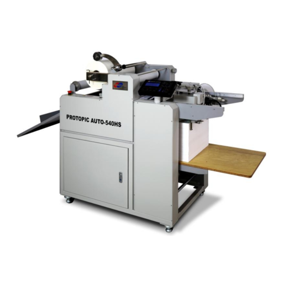
- Page 1 2015. 07. 29 USER MANUAL FOR PROTOPIC AUTO-540 HS Before operating the unit, please read this manual thoroughly and retain it for future reference. The design / specification of the machine could be changed for improvement without any prior notice.
- Page 2 INDEX ◐ SAFETY ◐ HOW TO LAMINATE page Important Safety Instruction page Safety Device ◐ MAINTENANCE page page Warning Stickers page ◐ TROUBLESHOOTING page ◐ INSTALLATION Packing Contents ◐ SPECIFICATION page page Main Devices page Move & Installation ◐ DIGITAL SLEEKING SOLUTION page Introduction of DIGITAL SLEEKING SOLUTION page...
- Page 3 Important Safety Instruction "Important Safety Instruction " is for the purpose of user's safety and prevention of Property loss. Read thoroughly and Use rightly according to the manual Warning : If you ignore this symbol, you could suffer serious injury or death Caution: If you ignore this symbol, you could receive a serious injury or loss of property This symbol means a prohibited action.
- Page 4 Important Safety Instruction It must be grounded for safety. Otherwise, this could be a cause of trouble and electric shock. Danger, Malfunction, loss of electricity could cause an electric shock Do not pull the plug or bend improperly ☞ Installation Do not use materials near a naked flame Do not use the machine in the sealed place.
- Page 5 Important Safety Instruction CAUTION ☞ Power When moving the product, turn off the power switch, disconnect the power plug from the socket When laminator is not in use, you must turn off the power switch, disconnect the power plug from the socket. ☞...
- Page 6 Safety Device Emergency Stop Switch ☞ Emergency Stop Switch When emergency situation happened, it stops the running motor(rollers) rotation and system operation. In case of emergency, use this switch. ☞ Position of E-Stop Switch ☞ How to use Press the Red button to operate the Emergency Stop Switch. E-Stop S/W All system is stopped when this is pressed.
- Page 7 Safety Device ☞ Laminating Roller Safety Cover It protects the workers from the burnings that may be occurred by touching hot roller Make sure the Safety Cover is always closed, except when Film is being loaded. ☞ Switch for Protection of Feeding Device It prevents the damage of feeding device from feeding table The system is not working once the safety switch is activated by abnormal raising of feeding table as right picture.
- Page 8 WARNING STICKERS WARNING STICKERS For the user safety, in the outer design, the below sticker is attached. Be cautious not to injured during operation. ☞Roller caution ☞ Higher Temperature Do not touch the roller and heating plate with your hand as you could be burnt. Do not touch on the heating part Roller's higher temperature and press can damage your body ☞Cutting Caution...
- Page 9 WARNING STICKERS WARNING STICKERS 9/66...
- Page 10 PACKING CONTENTS CONTENTS ITEMS Q'TY(EA) PROTOPIC AUTO - 540 HS LAMINATOR FEEDING TABLE PAPER GUIDE AIR COMPRESSOR AIR HOSE MANUAL SLEEKING IDLE ROLLER ASS'Y VACUM PUMP SEPARATOR ASS'Y AIR BLOWER ASS'Y REAR GUIDE ASS'Y GLASS TUBE FUSE(20MM) 250V/12.5A WRENCH SET SUCTION CUP 10/66...
- Page 11 MAIN DEVICES Main Devices Perforator Film Shaft Holder Pull Roller Pressure E-Stop S/W Adjustment Knob Decurling Adjustment Knob Tray Table Laminating Roller Pressure Adjustment Knob Feeding Table Control Panel 11/66...
- Page 12 MAIN DEVICES Film Shaft Rewinder Feeder Position Adjustment Knob Feeder Height Adjustment Knob Feeder Rewinder Tension Adjustment Knob Film Tension Adjustment Knob 12/66...
- Page 13 MAIN DEVICES Bursting Roller Power S/W 13/66...
- Page 14 MOVE & INSTALLATION UNPACK & MOVE ☞ Unpacking 1. Product is packed with vacuum aluminum packing materials to avoid corrosion and external packing is wooden crate. Each wooden panel is assembled with screws to prevent external shock 2. Wooden crate can be disassembled by 11mm box spanner. Disassemble the 5 panels on the left picture and remove vacuum packing materials.
- Page 15 MOVE & INSTALLATION ◑ If it requires to move it by caster wheel. 1. If a distance to move the laminator is less than 10m distance in the same area 2. Move the laminator gently with more than 4 persons at least. During it is moved, grip each corner of the machine. ◑...
- Page 16 MOVE & INSTALLATION ☞ Circumstance 1. Be installed in the flat place. 2. If inflammable or combustible substance is around, it might be a reason for a fire. 3. Sufficient ventilation is required to omit the heat from the laminator while laminating. ☞Installation Space Demension(WxLxH) 800*1675(2345)*1320...
- Page 17 MOVE & INSTALLATION ☞ Power Connection ◐ Specification of Main Power ◐ Phase of Plug & Power Socket Rated Voltage : 3P+N+E, 400VAC Power Cord Power Socket Rated Frequency : 50/60Hz Rated Current : 23A ◐ Phase & Voltage 20mm 1.
- Page 18 MOVE & INSTALLATION Connection to Power ◐ Power Cable is connected directly to the Switchboard Color&No. of Wire Wiring color L1 ( R ) Black Black L2 ( S ) Black Brown L3 ( T ) Black Black N(NEUTAL) Black Blue G(GROUND) Green&Yellow...
- Page 19 MOVE & INSTALLATION Connection to Power Warning Caution: This product consumes a large amount of electricity during its operation. If you connect this equipment with a power cable with insufficient capacity or an old cable, a fire might break out due to electrical leakage. Caution Caution : For your safety, please make sure that it's grounded properly.
- Page 20 MOVE & INSTALLATION How to connect Air Compressor ☞ How to connect Compressed air needs to be supplied into the laminator to activate the bursting roller and pressure on the laminating roller. After Power On, pull the cap Plug in at Independent Power Insert air hose in to the air compressor upward.
- Page 21 MOVE & INSTALLATION How to connect Vacuum Pump ☞ Vacuum Pump To generate air to feed substrates. Pressure for Air Compressor is set in the factory and it is recommended to use it at the setting value. NOTE : If the pressure status of Vacuum Pump is not good, suction/exhaust has to be checked firstly. Please ask to a supplier.
- Page 22 HOW TO USE CONTROL PANEL Details for Display ☞ Display Screen is composed of 3 kinds of screens, that is, Main Screen, Sub Screen 1 and Sub Screen 2. ☞ Main Screen : To check the main setting status in the laminator easily. ①...
- Page 23 HOW TO USE CONTROL PANEL ② "TOP:113℃ 123℃-W" - for display of Temp. & Jobs To display Setting / Current Temp. of Laminating Roller and Job Availability. Setting Temp. Range is "0~150℃". - "W"(WAIT) : means "not ready for lamination" (temp. is too low or too high for lamination). - "R"(READY) : means "ready for lamination".
- Page 24 HOW TO USE CONTROL PANEL ☞ Sub-Screen 1 : To check cylinders & motors operation status manually. ① PRESS : Display operation status of MAIN ROLLER. Press SPEED button to operate it manually. ② STOPPER : Display operation status of STOPPER. Press MAIN SCREEN MODE button to operate it manually.
- Page 25 HOW TO USE CONTROL PANEL ☞ Individual Buttons' functionality : In state of the machine turning on, the buttons' functionality are explained. A. LAMINATIG "RUN" : It is to activate the machine. If pressing the button, the laminating roller starts to be pressurized and rotates, and also the vacuum pump and feeding device are activated.
- Page 26 HOW TO USE CONTROL PANEL B. SCREEN "CONVERTER" It is to change the LCD screen mode showing the laminating status. If pressing the button, the screen is converted into the main screen, sub screen1, sub screen2. C. FEEDER "RUN" : it is to operate or stop VACUUM PUMP manually.
- Page 27 HOW TO USE CONTROL PANEL "SPEED" : In case of the lamination using NYLONEX(NYLON) & PERFEX(PET), rotate the bottom bursting roller in high speed to increase the film bursting quality. If the lamp is lit by pressing the button, the bottom roller run in high speed. But one more press of button makes the bottom roller run at normal speed.
- Page 28 HOW TO USE CONTROL PANEL "JOB" : It is to change Job mode. There are 13 kinds of JOB modes. - JOB mode selection : after the button is pressed, select the job mode desired according to the film kinds. It is possible that the user input the data of temperature, paper length, bursting position.
- Page 29 ERROR MESSAGE Main Screen ERROR Messages ERROR MESSAGE Cause of Trouble / How to troubleshoot If the communication (RS232C) between the main PCB & display PCB is in trouble, the message COM1 ERROR as the above picture would be blinking for every 0.5 sec till it would be recovered. If the communication (RS232C) between the main PCB &...
- Page 30 ERROR MESSAGE To display Alarm for Burst Motor Drive If input/output voltage is not be at the Motor Drive or encoder for motor control is defective, LAMI DRIVE ALARM is occurred. BURST DRIVE ALARM While this alarm is cured, if the RUN button is pressed, the alarm message is displayed for 3 secs. To release from alarm, press STOP button for 1 sec on SUB2 Mode.
- Page 31 ERROR MESSAGE Sub-Screen ERROR Messages ERROR MESSAGE Cause of trouble and How to troubleshoot Alarm for Main Drive LAMI DRIVE ALARM To release from alarm, press STOP button for 1 sec on SUB2 Mode. Alarm for Burst Drive BURST DRIVE ALARM To release from alarm, press STOP button for 1 sec on SUB2 Mode.
- Page 32 ERROR MESSAGE Message for STAND-BY status STAND BY STATUS Display FIGURE_W STAND BY POWER OFF STATUS Display FIGURE_X POWER OFF Display of Stand-by Time display the STAND-BY mode - If laminating roller setting temp. and real temp. is higher than 80℃, but system is in stop status, the STAND BY time is measured. 2 hours are passed from the measured time, the machine is in STAND BY mode.
- Page 33 How to use the Main Devices Feeding Area ① - SEPARATOR To prevent pick more than 2 sheets for feeding and to prevent twist the sheets by blower. example for Separator Install it as the right picture and recommendable pressed area is 5mm. Installation ②...
- Page 34 How to use the Main Devices ⑥ - Feeder Fixing Knob To fix a position of Feeder Adjust its position for stacked sheets and fix it. NOTE : If the Feeder would not be fixed, this could be a cause of damage on the feeder while lamination. ⑦...
- Page 35 How to use the Main Devices Feeding Area ① - Misfeeding Sensor To prevent contamination on laminating roller, if an error for feeding is occurred. When the feeding is stopped by feeding error, it stops machine operation. ② - Feeding Wheel & Brush To feed substrates to the Laminating Roller.
- Page 36 How to use the Main Devices ⑤ - Substrate Guide To pile up substrates, this guide is to avoid paper twist trouble in feeding / alignment process. Adjust position of guide for substrate size and stack substrates. ⑥ - Feeding Table To pile up substrates for lamination.
- Page 37 How to use the Main Devices Lamination Area ☞ How to adjust pressure on Laminating Roller Pressure on Laminating Roller can be adjusted by Pressure Controller and its pressure is displayed on the pressure gauge. Pull the controller to adjust pressure level and press it after adjustment is done. Pressure Adjustment Knob pressure gauge Turn the knob to the right to increase its roller pressure and...
- Page 38 How to use the Main Devices Cutting Area ☞ How to adjust Perforator To make holes at the edge lines of films for easy cutting of laminated results. Place the perforator at 1~3mm from film edge. Adjust its height to make holes on the films clearly. Perforator Height Adjustment Knob WARNING : For initial loading or for moving of perforator, loosen the height adjustment knob.
- Page 39 How to use the Main Devices Loading of Laminating Films ☞ Structure of Film Shaft 1. Film Shaft : To load the Laminating Roll Film. ① 2. Film Shaft Holder Fixing Pin : To avoid the movement of Film Shaft Support ②...
- Page 40 How to use the Main Devices Loading of Laminating Films ☞ Film Position In accordance with Single Side Lamination condition, the substrate width has to be wider than the film width by 5~10mm. Otherwise, the roller can be contaminated / damaged by glue on the Film. Position the Film at the inside of the substrate end by 3~5mm as the below picture.
- Page 41 How to use the Main Devices The Other Devices ☞ Main Power Switch Power Switch is to supply or to cut the Power to the Machine. Press the Switch to the "I" direction, the Power is ON and to the "O" direction to Power OFF. Power Switch has Circuit Breaker to cut the power supply for overload or over current status in the machine.
- Page 42 How to Laminate ☞ Preparation for Lamination ◐ Pile up substrates 1. Turn on the machine and the system is operated. 2. As the picture <1_1>, press "FEEDER TABLE UP/DOWN" on control panel to position the feeding table at the proper height. NOTE : If the feeder would not be at the origin point, the feeding table would not be moved upward.
- Page 43 How to Laminate NOTE : If stacking height is different due to deformed substrate, make it level with wedge type wooden piece. Picture <1_3> If an height is not leveled, this is the cause of feeding error. - Do not recommend to use the below conditioned substrate. Height Adjustment Height Difference This will bring feeding error or creasing on laminated results.
- Page 44 How to Laminate 2. To set up the feeder, adjust height distance between substrates top and shutter by 3~5mm. If substrate top height is too higher than the shutter, this will make 2~3 sheets to feed and if it is too lower than the shutter, this will make feeding error. 3~5mm ◐...
- Page 45 How to Laminate ◐ How to load film 1. Insert a film roll into the film shaft. Then, place the film shaft holder and insert the fixing pin. Procedure 1) Remove the Film Shaft Holder Fixing Pin. 2) Pull the Film Shaft Holder. 3) Insert or Remove film roll into or from Film Shaft.
- Page 46 How to Laminate ☞ Lamination ◐ Test Lamination 1. When temp. on laminating roller is reached to setting temp., test lamination is required to check setting status & laminating quality. Press "RUN" to make roller engage and lamination is processed. Picture <2_1>...
- Page 47 How to Laminate ※ Checking Points for Test Operation 1) Overlapped distance : Ideally, 3~5mm. If overlapped distance is too short, press "PAPER LENGTH" on "MAIN" mode of Control Panel to reduce setting value of substrate length. 2) Curling on Substrate : Check the curling status of substrate and adjust curling with decurler. It is natural thing to have curled laminated results for single side lamination.
- Page 48 Maintenance Clean the Roller ※ If the roller would not be cleaned; - Film could be stuck & wound on the roller. - The laminated results could be contaminated. ※ How to Clean - After lamination job is done, when the laminating roller temp. is lower than 80℃, clean the roller with "cotton" & "Isopropyl alcohol". WARNING : Isopropyl alcohol is required to clean the rollers.
-
Page 49: Troubleshooting
TROUBLESHOOTING Symptoms Cause of Trouble & Troubleshooting Feeding Area Feeding Table is not moved 1. If the feeder is not at origin point, upward. -> Press "FEEDER HOME" to make the feeder at origin point. 2. If Emergency Stop is activated, ->... - Page 50 TROUBLESHOOTING Symptoms Cause of Trouble & Troubleshooting More than 2 sheets are fed 1. Separator is at wrong position. -> Recommend area of plate of separator to substrate is 5~7mm. 2. Distance between top end of Shutter and substrate top is less than 3mm. or substrate top is higher than shutter height.
- Page 51 TROUBLESHOOTING Symptoms Cause of Trouble & Troubleshooting Lamination Laminating Roller is not 1. If safety switch at roller cover is opened. -> Close the roller cover safety switch. Area operated. 2. This could be caused by motor for laminating roller or chain is defective. ->...
- Page 52 TROUBLESHOOTING Symptoms Cause of Trouble & Troubleshooting Wrinkles are on the laminated 1. Nip Roller is contaminated by film / substrate that is stuck on it. -> Clean the roller with cleaner. results 2. Nip Roller is defective. (trouble in production, damaged surface, etc.) ->...
- Page 53 TROUBLESHOOTING Symptoms Cause of Trouble & Troubleshooting Cutting Area Bursting Roller is not 1. Defective Bursting Roller Motor or Chain -> Contact to a supplier. operated. 2. Fuse blows -> Replace it with 250V/8A that is packed with machine. 3. Defective Air Compressor -> Contact to a supplier. Cutting is not good 1.
- Page 54 SPECIFICATION Items PROTOPIC AUTO - 540 HS Dimension (W*L*H)(mm) 800*1675*1320 Max. Laminating Speed(m/min) Max. Substrate Size(W*L)(mm) 540*750 Min. Substrate Size(W*L)(mm) 210*254 Substrate Thickness Range(g/㎡) 120~350 Laminating Films POLYNEX, PERFEX, NYLONEX FILM Power Requirement AC 380 ~ 400V / 21A Power Consumption 5 kw Warm-Up Time 7 minutes...
- Page 55 DIGITAL SLEEKING SOLUTION - Introduction DIGITAL SLEEKING SOLUTION GMP DIGITAL SLEEKING SOLUTION is the epoch solution to provide various value-added products with Whole Page & Spot Gloss/Matt/Hologramming with GMP Laminators. 1. SLEEKING (GLOSS & MATT FINISH) SLEEKING FOIL : GLOSS SLEEKING FOIL, MATT SLEEKING FOIL 2.HOLOGRAM SLEEKING FOIL...
- Page 56 SLEEKING (GLOSS & MATT FINISH) 1.GLOSS/MATT SLEEKING With GMP GLOSS SLEEKING FOIL & MATT SLEEKING FOIL, the surface of Toner Based Prints / Digital Prints can be changed for higher quality of results. Conditions for GLOSS/MATT SLEEKING FOILS Model Speed Set Temp.(℃)
- Page 57 SLEEKING (GLOSS & MATT FINISH) 2. Whole Page Gloss / Matt SLEEKING SOLUTION ① Whole Page Gloss / Matt Sleeking POD Prints Film Loading FILM & LAMINATOR SLEEKING FINISH (DIGITAL PRINT) PRINTER FILM HP INDIGO 3500 GLOSS SLEEKING FOIL Refer to the Pic. 1.2 Temp.
- Page 58 SLEEKING (GLOSS & MATT FINISH) 2. Spot Gloss/Matt SLEEKING SOLUTION with Prints ② Spot Gloss / Matt Sleeking POD Prints (DIGITAL PRINT) POD Prints SLEEKING FINISH (DIGITAL PRINT) OFFSET Prints Temp. / Speed Setting Refer to the Table 1.1 PRINTER HP INDIGO 3500 (Table 1.3) Spot Gloss / Matt Sleeking XEROX 5252...
- Page 59 Image only. 5. Sleeking on the Printed Surface in process of (Table 1.2) 1.Cut the Car Image(Picture 6. Only the Spot 3. Laminate in GMP Image has Sleeking 1.2) with Image Editing 4. Print the Spot Image Laminator with GMP Effect.
- Page 60 SLEEKING(HOLOGRAM FINISH) 1.HOLOGRAM SLEEKING GMP Hologram Sleeking Foil makes added-value products for Toner based Digital Prints. Conditions for HOLOGRAM SLEEKING FOIL HOLOGRAM SLEEKING FOILS Model ① SPARKLE-HOLOGRAM Speed Set Temp.(℃) Pressure (MPa) PROTOPIC III Series ② HIPER PLAID-HOLOGRAM ③ CRYSTAL-HOLOGRAM (Table 2.1)
- Page 61 SLEEKING(HOLOGRAM FINISH) 2. Whole Page HOLOGRAM SLEEKING SOLUTION ① Whole Page Hologram Sleeking POD Prints FILM & LAMINATOR Foil Loading SLEEKING FINISH (DIGITAL PRINT) PRINTER FILM Refer to the Picture 2.1 Temp. / Speed Setting HP INDIGO 3500 HOLOGRAM SLEEKING FOIL Refer to the Table 2.1 XEROX 5252 LAMINATOR...
- Page 62 SLEEKING(HOLOGRAM FINISH) 2. Spot HOLOGRAM SLEEKING SOLUTION ② Spot Hologram Sleeking POD Prints (DIGITAL PRINT) SLEEKING POD Prints FINISH OFFSET Prints Temp. / Speed Setting Refer to the Table 2.1 PRINTER HP INDIGO 3500 XEROX 5252 (Table.2.3) Spot Hologram Sleeking 6.
- Page 63 5. Sleeking on the Printed Surface in process of (Table 2.2) d 1.Cut the Carrot 6. Only the Spot Image 4. Print the Spot 3. Laminate in GMP Image(Picture 2.1) with has Sleeking Effect. Image on the Laminator with GMP Image Editing Program Laminated Surface.
- Page 64 METALLIC SLEEKING 1.SPOT METALLIC SLEEKING GMP METALLIC SLEEKING FOIL makes different effect on the printed area for highlight. Conditions for METALLIC SLEEKING FOIL METALLIC SLEEKING FOIL ① GOLD Model ② SILVER Speed Set Temp.(℃) Pressure (MPa) PROTOPIC III Series (Table 3.1) How to load the Foils (Picture 3.1)
- Page 65 Temp. / Speed Setting PRINTER Refer to the Table 3.1 HP INDIGO 3500 XEROX 5252 (Table.3.3) Spot Gold/Silver Metallic Sleeking 3. Laminate in GMP 4. Print the Background Image. Laminator with GMP Sleeking Foil. 1.Cut the Spot Image(Picture 3.1) with 2.
- Page 66 FILM SPECIFICATION SLEEKING FILM MEATALLIC FOIL (GOLD,SILVER,BLUE,GREEN,RED,VIOLET,PINK) SINGLE COLOR FOIL 3000M MULTI COLOR FOIL 3000M HOLOGRAM FOIL 3000M SLEEKING FOIL GLOSS 77CORE * 1000M,2000M MATT 77CORE * 1000M,2000M DUAL 77CORE * 1000M,2000M HOLOGRAM SLEEKING FOIL - SPECTRUM,MILKYWAY,CRYSTAL,STAR,MOSAIC,SPARKLE,HYPER PLAID HOLOGRAM SLEEKING FOIL-PET12 77CORE * 1000M HOLOGRAM SLEEKING FOIL-PET25 77CORE * 1000M...
Need help?
Do you have a question about the PROTOPIC AUTO-540 HS and is the answer not in the manual?
Questions and answers