Table of Contents
Advertisement
*P516-100*
P516-100
Para el idioma español, navegue hacia www.allegion.com/us
Pour la portion française, veuillez consulter le site www.allegion.com/us
WRI400
Wireless Reader Interface
Instructions for WRI 400
MOUNT
THIS
SIDE UP
J3
1
1
MCLR
TP21
VDD
TP22
LED1
GND
TP23
RB7
TP24
RB8
TP25
OPEN
IDAT
DEBUG
ICLK
1
RX
+3.3V
TX
GND
J1
S3
19
LED3
RX/TX
20
RESET
REL1
S2
J6
1
STR
NO
LINK
STR
C
C
STR
NC
LED4
AUX
STRIKE
NO
AUX
C
AUX
LED5
NC
ALR_NO
ALR_C
LED6
ALARM
ALR_NC
REL2
REL3
J2
1
LED7
GND
LID
PWR/
TAMPER
TAMPER
1
J13
SWITCH INPUT
23394075_C
LED2
USB
1
J5
USB
1
2
S1
SCHLAGE
RELAY
STATUS
AUX
U4
+5V
LINE
LED9
LED8
U5
B+
A-
1
1
J11
J12
1
J10
1
J17
RS485
READER1
PRIMARY SIDE
BATTERY_HOLDER1
COIN CELL NOT NEEDED
IF RADIO BOARD PRESENT
+12V
J8
LINE
BATT
1
12/24VDC
1
J7
C32
J9
AA
1
BATT
1
J18
READER2
Advertisement
Table of Contents

Summary of Contents for Schlage WRI400
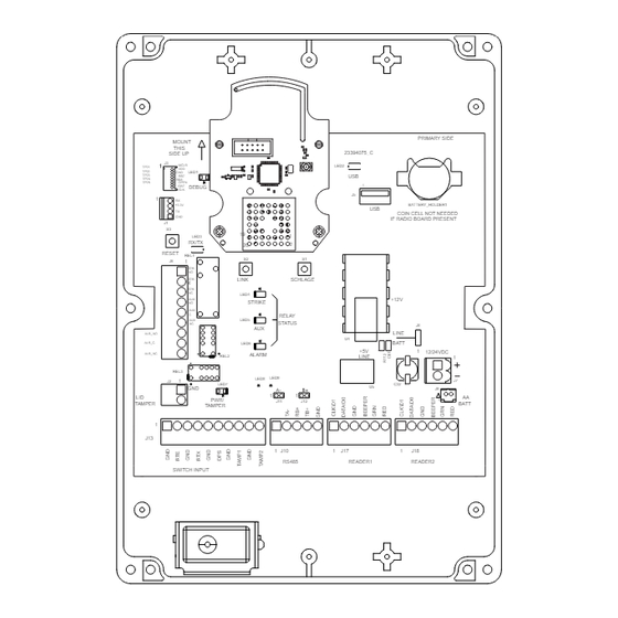
- Page 1 *P516-100* P516-100 WRI400 Wireless Reader Interface Instructions for WRI 400 PRIMARY SIDE MOUNT THIS 23394075_C SIDE UP LED2 MCLR TP21 TP22 LED1 TP23 TP24 TP25 OPEN IDAT DEBUG ICLK BATTERY_HOLDER1 +3.3V COIN CELL NOT NEEDED IF RADIO BOARD PRESENT LED3...
-
Page 2: Table Of Contents
PIM400 and WRI400 location ..................5 Remote antenna......................5 Antenna location and safety ..................5 Antenna grounding ......................6 Terminate the coax whip at the WRI400 ...............6 Outdoor gate applications .....................7 Elevator applications .....................8 Weather-tight installation of the WRI400 ...............9 Non weather-tight installation of the WRI400 ..............9 Mounting the WRI400 ....................9... -
Page 3: Overview
Overview The Schlage Wireless Reader Interface (WRI400) is an open architecture Wireless Access Point Module (WAPM) designed to interface with third-party panels through a Panel Interface Module (PIM400-TD2, PIM400-485) by using radio frequency (RF) communication. • Interfaces credential readers and portal access control with third-party panels. -
Page 4: Getting Started
4. Install the UL listed reader(s). 5. Install the WRI400. 6. Install a UL/ULC listed power supply for the WRI400 and the readers. The power supply must be compatible with all components and must have the capacity to power the WRI400 and the readers. -
Page 5: Install The Wri400
Locate within 15 cable feet (4.5 meters) of the PIM400 or the WRI400. • Locate for best RF line-of-sight path with the WRI400 that will be linked to the PIM400. • Do not locate the WRI400 and antenna or the antenna and PIM400 on separate floors of a building. -
Page 6: Antenna Grounding
1. Drill a Z\x” (13 mm) hole in the top of the WRI400 enclosure as shown to accommodate the mounting of the coax whip to be connected to the WRI400 radio board. -
Page 7: Outdoor Gate Applications
PIM400 and mount the antenna on the outside the building in direct line-of-sight to the WRI400(s). If the WRI400 is mounted on a metal wall or wall with metal mesh, refer to page 9 for installation instructions. -
Page 8: Elevator Applications
Locate the PIM400 within range of the antenna module’s coax cable (15 cable feet (4.5 meters)). • Mount the antenna module with direct line-of-sight to the WRI400 throughout the entire travel of the cab through the shaft. Ensure that structural members do not obstruct line-of-sight to the WRI400. -
Page 9: Weather-Tight Installation Of The Wri400
2. Mark the four mounting holes at the corners of the WRI400 housing using the housing as a template. 3. Remove the WRI400 and drill the four holes, >\cx” diameter drill bit, 1C\v” (44 mm) deep. 4. Orient the WRI400 vertically with the radio board at the top of the enclosure. -
Page 10: Wiring The Wri400 To Access Control Peripherals
Wiring the WRI400 to access control peripherals The WRI400 will monitor two (2) UL listed credential readers, up to five (5) status inputs and control two (2) relays for access control peripherals. Some of the connections are optional based on the specific application of the WRI400. See WRI400 Cable/wire specifications on page 10 for more information. - Page 11 − 12 or 24 VDC 500 mA WRI400 Earth Earth Portal Output Connections Portal Status Signals Reader 1 Reader 2 Power Supply Ground Ground Typical WRI400 to readers and portal wiring diagram 11 • Schlage • WRI400 user guide...
-
Page 12: Portal Inputs
5V may cause damage to either the WRI400 or the reader. Connect the shield of the portal input cables to the appropriate WRI400 GND terminal. To ensure proper integration with the ACP, the switch input may be changed from the default condition using the Schlage Utility Software (SUS) on the HHD. -
Page 13: Portal Outputs
Use a properly rated transient voltage suppression (TVS) diode (or silicon avalanche diode). Install the suppressor within 18 inches (46 cm) of the switched electrical load. 13 • Schlage • WRI400 user guide... - Page 14 WRI400 signal wiring. Do not run portal output wires in the same cable or conduit as any other WRI400 wiring. Connect the shield of the portal output cables to the appropriate earth ground terminal of the electrical lock/load or auxiliary load power supply.
-
Page 15: Credential Readers
Connect the shield of the Reader 1 cable to the WRI400 J17-3 terminal (GND). Connect the shield of the Reader 2 cable to the WRI400 J18-3 terminal (GND). Do not connect the cable shield at the credential reader. Reader input ports are designed for 5V logic. Any voltage greater than 5V may cause damage to either the WRI400 or the readers. -
Page 16: Power Failure Modes
SUS must also be configured to enable fail safe mode. Strike and auxiliary relays need not be configured the same. • Third party locking devices must have some form of uninterruptible power supply for the WRI400 to control their power failure mode. 16 • Schlage • WRI400 user guide... -
Page 17: Handheld Device (Hhd)
3. Log in to the SUS software. (Refer to the SUS User Guide for log-in procedure.) Make sure the HHD connection type is set to “USB Connection”. 4. Connect the HHD to the WRI400 USB port (J5). The WRI400’s USB LED will blink green. PRIMARY SIDE... -
Page 18: Construction Access Mode
Solid red or fast red blinks Poor or no link The WRI400 will fail to link if it is not in RF range of the PIM400. Refer to PIM400 and WRI400 location on page 5 for distance specifications. Refer to Troubleshooting on page 20 for more information on linking. -
Page 19: Reset To Factory Defaults
Test Test the WRI400 with power applied 1. The lid tamper LED will blink green when the WRI400 cover is removed and will light solid green when the lid tamper switch is pressed. 2. Most readers are designed to function independently of the WRI400. If the reader’s LED and beeper performance is irregular or unexpected, refer to the instructions that came with the reader. -
Page 20: Troubleshooting
LINK PIM400. Maximum distance is 200 feet (61 meters). is unsuccessful attempt The WRI400 and the PIM400 must be located on the No data is getting same floor of the building. to the ACP Make sure the PIM400 is in link mode before No data is getting attempting to link to the WRI400. -
Page 21: Important Things To Know Before Calling Technical Service
Aux relay action is assigned by the access control panel. A credential must have aux relay rights before the ACP will command the WRI400 to activate the aux relay. The aux relay will activate only when the WRI400 is in normal operating mode (the ACP does not communicate with the WRI400 when in Construction Mode). -
Page 22: Wri400 Led Reference
WRI400 LED reference 22 • Schlage • WRI400 user guide... -
Page 23: Fcc/Ic Statements
Note: The intended use of this module is not for the general public. It is generally for industry/commercial use only. This transceiver is to be professionally installed in the end product by Allegion, and not by a third party. The Schlage XPB-COMAD400V2 900 MHz Communication Board Module will not be sold to third parties via retail, general public or mail order. - Page 24 Approved antenna list: The required antenna impedance is 50 ohms. PCB trace antenna with a 5.7dBi maximum gain p/n: 23520587, Dual Beam Antenna with a 3.5dBi gain (ANT400-REM-HALL) p/n: 23530579, Multi band Directional Panel antenna with 8.5dBi gain (ANT400-REM-I/O+dB) p/n: 23530553, Dual Band Quasi-Omni Panel Antenna with 4.5dBi gain (ANT400-REM-I/O) p/n: 23520561, Multi band Omni Antenna with 2dBi gain (ANT400-REM-CEILING) Antennas having a gain greater than the antenna type approved in the list are strictly prohibited for use with this device.
Need help?
Do you have a question about the WRI400 and is the answer not in the manual?
Questions and answers