Advertisement
Table of Contents
- 1 Installation
- 2 Wiring
- 3 Option 26 - Minimum Cooling Set Point
- 4 Option 27 - Maximum Heating Set Point
- 5 Option 99 - Reset to Factory Defaults
- 6 System Start-Up and Checkout
- 7 Operation
- 8 Configuration
- 9 Troubleshooting
- 10 Wiring Diagrams
- 11 Terminal Board
- 12 Manufacturer Reserves the Right to Discontinue, or Change at any Time, Specifications or Designs Without Notice and Without Incurring Obligations
- 13 Thermostat Configuration Record
- 14 Configuration Options
- 15 User Setting
- Download this manual
IMPORTANT: Read entire instruction before installing
the thermostat.
CONTENTS
SAFETY CONSIDERATIONS . . . . . . . . . . . . . . . . . . . . . . 1
GENERAL . . . . . . . . . . . . . . . . . . . . . . . . . . . . . . . . . . . . . . . . 1
PACKAGE CONTENTS . . . . . . . . . . . . . . . . . . . . . . . . . . . 1
INSTALLATION CONSIDERATIONS . . . . . . . . . . . . . .1,2
Power . . . . . . . . . . . . . . . . . . . . . . . . . . . . . . . . . . . . . . . . . . . . 1
Wiring. . . . . . . . . . . . . . . . . . . . . . . . . . . . . . . . . . . . . . . . . . . . 2
Thermostat Location . . . . . . . . . . . . . . . . . . . . . . . . . . . . . 2
INSTALLATION . . . . . . . . . . . . . . . . . . . . . . . . . . . . . . . . . .2,3
CONFIGURATION . . . . . . . . . . . . . . . . . . . . . . . . . . . . . . 3-6
Entering and Exiting Configuration Mode . . . . . . . . 3
Configuration Options . . . . . . . . . . . . . . . . . . . . . . . . . . . 3
Exiting Configuration Mode . . . . . . . . . . . . . . . . . . . . . . 6
SYSTEM START-UP AND CHECKOUT . . . . . . . . . . . . 6
Installer Test Mode . . . . . . . . . . . . . . . . . . . . . . . . . . . . . . . 6
Terminating Installer Test . . . . . . . . . . . . . . . . . . . . . . . . 6
Checklist . . . . . . . . . . . . . . . . . . . . . . . . . . . . . . . . . . . . . . . . . 6
OPERATION . . . . . . . . . . . . . . . . . . . . . . . . . . . . . . . . . . . . .6,7
Mode Selection. . . . . . . . . . . . . . . . . . . . . . . . . . . . . . . . . . . 6
Fan Selection . . . . . . . . . . . . . . . . . . . . . . . . . . . . . . . . . . . . 6
Set Temperature Selection . . . . . . . . . . . . . . . . . . . . . . . 6
Batteries . . . . . . . . . . . . . . . . . . . . . . . . . . . . . . . . . . . . . . . . . 6
Display Lighting. . . . . . . . . . . . . . . . . . . . . . . . . . . . . . . . . . 7
Remote Sensor Temperature Display. . . . . . . . . . . . . 7
Timers . . . . . . . . . . . . . . . . . . . . . . . . . . . . . . . . . . . . . . . . . . . 7
Five-Minute Compressor Timeguard . . . . . . . . . . . . . 7
Minimum On Timer . . . . . . . . . . . . . . . . . . . . . . . . . . . . . . . 7
Cycle Timer . . . . . . . . . . . . . . . . . . . . . . . . . . . . . . . . . . . . . . 7
Staging Timer . . . . . . . . . . . . . . . . . . . . . . . . . . . . . . . . . . . . 7
TROUBLESHOOTING. . . . . . . . . . . . . . . . . . . . . . . . . . . . . 7
Space Temperature Sensor Failure . . . . . . . . . . . . . . . 7
Fan Failure . . . . . . . . . . . . . . . . . . . . . . . . . . . . . . . . . . . . . . . 7
Memory Failure . . . . . . . . . . . . . . . . . . . . . . . . . . . . . . . . . . 7
Equipment Outputs . . . . . . . . . . . . . . . . . . . . . . . . . . . . . . 7
WIRING DIAGRAMS . . . . . . . . . . . . . . . . . . . . . . . . . . . 7-17
THERMOSTAT CONFIGURATION RECORD . . . . CL-1
SAFETY CONSIDERATIONS
Read and follow manufacturer instructions carefully. Fol-
low all local electrical codes during installation. All wiring
must conform to local and national electrical codes. Improper
wiring or installation may damage thermostat.
Recognize safety information. This is the safety alert sym-
bol
. When the safety alert symbol is present on equipment
or in the instruction manual, be alert to the potential for person-
al injury.
Manufacturer reserves the right to discontinue, or change at any time, specifications or designs without notice and without incurring obligations.
Catalog No. 04-53330027-01
Installation Instructions
Part Number 33CSCNACHP-01
Page
Printed in U.S.A.
Non-Programmable
Commercial Thermostat
Understand the signal words DANGER, WARNING, and
CAUTION. These words are used with the safety alert symbol.
DANGER identifies the most serious hazards which will result
in severe personal injury or death. WARNING signifies a haz-
ard which could result in personal injury or death. CAUTION
is used to identify unsafe practices which would result in minor
personal injury or property damage.
GENERAL
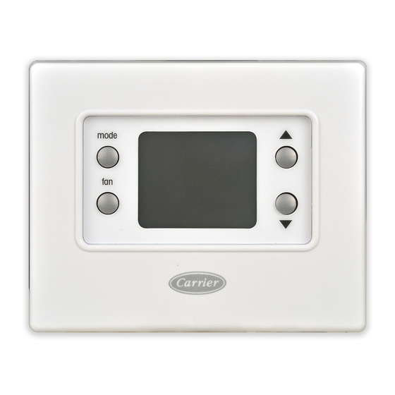
Carrier's Comfort Pro non-programmable thermostats are
wall-mounted, low-voltage thermostats that maintain room
temperature by controlling the operation of a heating and/or air
conditioning system (Fig. 1). This thermostat can be used with
a heat pump, air conditioner or water source heat pump opera-
tion. A variety of features are provided including battery opera-
tion, separate heating and cooling set points, auto changeover,
keypad lockout, backlighting, and built-in installer test.
This Installation Instruction covers installation, configura-
tion, and start-up of the Comfort Pro non-programmable ther-
mostat. For operational details, consult the Owner's Manual for
this specific thermostat.
mode
fan
Fig. 1 — Comfort Pro Non-Programmable
Commercial Thermostat
PACKAGE CONTENTS
1 — Thermostat
1 — Backplate (mounting base)
2 — Screws and anchors
INSTALLATION CONSIDERATIONS
The thermostat will obtain full operating power
Power —
one of two ways: full 24 volt AC (50/60 Hz) power via the Rc/
Rh and C terminals or two AA alkaline batteries. The 24 vac
operation is preferred, if available. Battery operation is used
when there are not enough wires to support 24 vac operation.
Form 33CS-75SI
Pg 1
Comfort™ Pro
°
F
a33-9224
7-13
Replaces: 33CS-70SI
Advertisement
Table of Contents

Related Manuals for Carrier Comfort Pro 33CSCNACHP-01


Summary of Contents for Carrier Comfort Pro 33CSCNACHP-01
- Page 1 PACKAGE CONTENTS ......1 Carrier’s Comfort Pro non-programmable thermostats are INSTALLATION CONSIDERATIONS ....1,2 wall-mounted, low-voltage thermostats that maintain room Power .
-
Page 2: Installation
When the battery is low, a Low Battery indication will be dis- 3. Press the thumb release at the top of the thermostat and played to the user. snap apart carefully to separate backplate from the ther- mostat and expose mounting holes. For an air conditioning system, up to six wires are needed for 24 vac operation and one less wire for battery operation. - Page 3 These configuration op- turn air temperature. tions are stored to the internal memory so they are retained NOTE: Carrier sensors 33ZCT55SPT, 33ZCSENDAT, through a power outage. The availability of some configuration 33ZCSENSAT, and 33ZCSENOAT may be used for standard options will be dependent upon other conditions in the thermo- space temperature sensor averaging.
- Page 4 sensed in one of three ways: the local sensor (L) located on the OPTION 13 — SPACE TEMPERATURE DISPLAY thermostat, the remote sensor (r), or the average of local and ADJUSTMENT (OFFSET) — This configuration is the remote sensors (Lr). number of degrees to be added to the displayed temperature to calibrate or deliberately miscalibrate the measured space tem- Selection: L, r, Lr...
-
Page 5: Option 26 - Minimum Cooling Set Point
Selection: –5 to 5 (number of degrees F added to the out- OPTION 26 — MINIMUM COOLING SET POINT — door air temperature reading to "calibrate" the tempera- This parameter establishes the minimum cooling set point that ture sensor) the user is allowed to set. If the equipment type is Cool Only, the lower limit is 55 F and the upper limit is 90 F. -
Page 6: System Start-Up And Checkout
in its normal operating mode, consult the Owner's To exit the configu- Exiting Configuration Mode — Manual. ration mode, press the fan button. 2. If the equipment is to be left in operation, the set points and operating mode must be properly selected. SYSTEM START-UP AND CHECKOUT 3. -
Page 7: Troubleshooting
WIRING DIAGRAMS hour limits. It can be defeated for one cycle by simultaneously pressing the fan and up keys. System wiring diagrams are provided for typical Carrier equipment. See Fig. 6-24. The staging timer enforces a minimum Staging Timer —... - Page 8 33CSCNACHP-01 6 24 VAC COMMON a33-9243 Fig. 6 — Thermostat Wiring — 42B Motor Controls — Single-Phase Only, 3-Phase Only, Single-Phase with Interlocking Disconnect, and 3-Phase with Interlocking Disconnect 33CSCNACHP-01 6 24 VAC HEAT 1 COMMON a33-9244 Fig. 7 — Thermostat Wiring — 42B Motor Controls — Single-Phase and 3-Phase with Interlocking Disconnect and Single-Stage Electric Heater...
- Page 9 33CSCNACHP-01 6 24 VAC HEAT 1 COMMON HEAT 2 a33-9245 Fig. 8 — Thermostat Wiring — 42B Motor Controls — 3-Phase with Interlocking Disconnect and 2-Stage Electric Heater 33CSCNACHP-01 Unit CTB Thermostat * X is not wired to thermostat. a33-9246 Fig.
- Page 10 33CSCNACHP-01 a33-9247 Fig. 10 — Thermostat Wiring — 50EJQ,EWQ024,028 Heat Pump Units 33CSCNACHP-01 a33-9248 * X is not wired to thermostat. Fig. 11 — Thermostat Wiring — 50HJQ004-016 Units...
- Page 11 DUCT HEATER INSTALL JUMPER G TO QT 33CSCNACHP-01 COMPLETE C COMPLETE C a33-9309 FIRST SECOND COMPRESSOR COMPRESSOR Fig. 12 — Thermostat Wiring — 50HQL, KQE, KQL, P1, PC, PEC, PS, PSW, PT, RHC, RHE, RHR, RHS, RTG, RVC, RVE, RVR, RVS, RWS, VQL Water Source Heat Pump Units with Complete C Controls and Duct Heating Option DELUXE D 33CSCNACHP-01...
- Page 12 COMPLETE C 33CSCNACHP-01 FIRST COMPRESSOR a33-9302 Fig. 14 — Thermostat Wiring — 50HQL, KQE, KQL, P1, PC, PEC, PS, PSW, PT, RHC, RHE, RHR, RHS, RTG, RVC, RVE, RVR, RVS, RWS,VQL Water Source Heat Pump Units with Complete C Controls 33CSCNACHP-01 a33-9251 Fig.
-
Page 13: Terminal Board
33CSCNACHP-01 TERMINAL BOARD W2† a33-9308 *Connection not required. †W2 connection not required on units without electric heating. Fig. 16 — Thermostat Wiring — 50HCQ,TCQ Rooftop Units 33CSCNACHP-01 IPD/X* a33-9307 *Connection not required. Fig. 17 — Thermostat Wiring — 50HJQ014,016 Heat Pump Units... - Page 14 CONNECTION BOARD (TB) 33CSCNACHP-01 LLSV-1 X*/8 LLSV-2 38ARD014-024 38ARD007-02 LEGEND *Connection not required. — Indoor Fan Contactor a33-9304 LLSV — Liquid Line Solenoid Valve Fig. 18 — Thermostat Wiring — 38ARD Commerical Split System Units INDOOR UNIT 33CSCNACHP-01 FAN COIL 40RMQ SERIES OUTDOOR UNIT a33-9305...
- Page 15 OUTDOOR INDOOR CONNECTION CONNECTION BOARD (TB) BOARD (TB) 33CSCNACHP-01 ONLY REQUIRED FOR 38AUQ HEAT PUMP a33-9303 Fig. 20 — Thermostat Wiring — 38AU Commercial Split System Units with 40RUA Air Handler Units TERMINAL BLOCK JUMPER FOR ELECTRIC HEAT HEAT PUMP ACCESSORY WIRING CONNECT TO...
- Page 16 33CSCNACHP-01 OAT SENSOR REMOTE ROOM SENSOR a33-9323 Fig. 22 — Thermostat Wiring — Outdoor Air Temperature and Remote Room Temperature Sensors 33CSCNACHP-01 STRN SENSOR 3 SENSOR 1 SENSOR 2 SENSOR 4 a33-9324 Fig. 23 — Thermostat Wiring — Space Temperature Sensor Averaging Wiring ( 4 Sensor Application)
- Page 17 33CSCNACHP-01 STRN SENSOR 1 SENSOR 2 SENSOR 3 SENSOR 4 SENSOR 5 SENSOR 6 a33-9325 SENSOR 7 SENSOR 8 SENSOR 9 Fig. 24 — Thermostat Wiring — Space Temperature Sensor Averaging Wiring (9 Sensor Application)
-
Page 18: Manufacturer Reserves The Right To Discontinue, Or Change At Any Time, Specifications Or Designs Without Notice And Without Incurring Obligations
© Carrier Corporation 2013 Manufacturer reserves the right to discontinue, or change at any time, specifications or designs without notice and without incurring obligations. Catalog No. 04-53330027-01 Printed in U.S.A. Form 33CS-75SI Pg 18 7-13 Replaces: 33CS-70SI... -
Page 20: Thermostat Configuration Record
Temperature Display Option 99 _____ Reset Factory Defaults © Carrier Corporation 2013 Manufacturer reserves the right to discontinue, or change at any time, specifications or designs without notice and without incurring obligations. Catalog No. 04-53330027-01 Printed in U.S.A. Form 33CS-75SI...
Need help?
Do you have a question about the Comfort Pro 33CSCNACHP-01 and is the answer not in the manual?
Questions and answers