
Related Manuals for Hydro-Gear T2


Summary of Contents for Hydro-Gear T2
- Page 1 We set the wheels in motion. ® T2™ Integrated Hydrostatic Transaxle Service and Repair Manual BLN-52749 November 2006...
-
Page 2: Table Of Contents
Troubleshooting ......8 T2 Transaxle Exploded View ....35 Service and Maintenance . -
Page 3: Foreword
H e a d q u a r t e r e d i n S u l l i v a n , I l l i n o i s , Internal repair procedures require that the Hydro-Gear ® is a world leader in the design, transaxle unit be removed from the vehicle. -
Page 4: Description And Operation
DESCRIPTION AND OPERATION INTRODUCTION The T2 has a self contained fl uid supply and The purpose of this manual is to provide in- formation useful in servicing the Hydro-Gear ® an internal fi lter. The fl uid is forced through T2 ™... -
Page 5: Hydraulic Schematic
The oil supply for the hydraulic system is “lost” from the hydraulic loop through leak of the T2 ™ is also utilized for lubricating the paths designed into the product for lubrication components of the fi nal drive assembly. -
Page 6: External Features
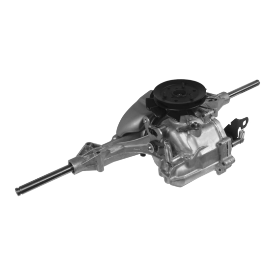
EXTERNAL FEATURES T2 ™ Bypass Arm Control Arm Input Shaft Side Housing Main Housing RH Axle LH Axle Oil Fill Plug Expansion Tank — Top View — Input Shaft Control Arm Expansion Tank Brake Arm RH Axle LH Axle Side Housing Main Housing —... - Page 7 EXTERNAL FEATURES T2 ™ Expansion Tank Bypass Arm Control Arm LH Axle — Outboard View—Left — Pulley Oil Fill Plug Expansion Tank Bypass Arm Brake Arm RH Axle Brake Rotor — Outboard View—Right — T2™...
-
Page 8: Technical Specifications
16 in (406 mm) 18 in (457 mm) PRODUCT IDENTIFICATION The model and confi guration of the T2 can be determined from the label shown below. H Y D R O - G E A R T2-AABC-2X1A-1CXX T2-AABC-2X1A-1CXX 6 352 K1 476... -
Page 9: Safety
The fl oor should be clean and dry, and all ex- Certain safety precautions must be observed tension cords or similar trip hazards should be while servicing or repairing the T2. This section removed. addresses some of these precautions but must... -
Page 10: Troubleshooting
TROUBLESHOOTING In many cases, problems with the T2 ™ are WARNING not related to a defective transaxle, but are caused by slipping drive belts, partially engaged Do not attempt any servicing or ad- bypass valves, and loose or damaged control justments with the engine running. -
Page 11: Service And Maintenance
fi ll port location. adjustment of the parking brake. Fill the T2 to the bottom of the oil fill port 6. Inspect the vehicle control linkage to the threads. directional control arm on transaxle. Also, insure the control arm is securely fastened Recheck the fl... -
Page 12: Fluid Change Procedure
5. After all the oil is drained from the transaxle, remove the expansion tank by removing the As the T2 transaxle is operated, oil in the self tapping bolt (10-32 x ½) and ratchet transaxle housing heats up which causes the fastner that holds the tank to the housing. -
Page 13: Purging Procedures
3. High operation temperature and excessive and reverse at normal speed purging is expansion of oil. complete. Before starting, make sure the transaxle/trans- mission is at the proper oil level. If it is not, fi ll to the specifi cations outlined on page 9. T2™... -
Page 14: Return To Neutral Setting
Refer to Figure 4. Recheck according to steps 3 and 4. Refer to Figure 4. Spring (167) Screw (41) RTN Control Arm (160) Lock Down Screw (168) Bushing (165) Scissor Arm (162) RTN Neutral Arm (161) Figure 4, Return to Neutral T2™... -
Page 15: Brake Maintenance
100 in-lbs (11 Nm) torque. The friction pack nut is then backed off per the vehicle manufacturer’s (130) specifi cations. (132) (134) Friction Pack Nut (121) (133) (124) Figure 5, Brake Setting Figure 6, Friction Pack Adjustment T2™... -
Page 16: Tear Down And Reassembly
The item reference num- IMPORTANT: When internal repair is performed bers in each illustration are for assembly on the T2 ™ , the fi lter assembly must be re- instructions only. See page 36 for part names placed. -
Page 17: Tools
360-520 in-lbs [40.7-58.8 Nm] Fan Nut HFHCS 1/4-20 x 0.75 50-80 in-lbs [5.7-9.0 Nm] Fan Screws Lock Down Screw 135-155 in-lbs[15.3-17.5 Nm] RTN Arm As a general rule, use the low end of the torque spec on fasteners when reassembling the unit. T2™... -
Page 18: Transaxle Removal
TRANSAXLE REMOVAL NOTE: It is necessary to remove the T2 ™ from Do not disassemble the unit any far- the vehicle before performing the repair ther than necessary to accomplish the procedures presented in this section. required repairs. Before starting any disassembly, make... -
Page 19: Fan And Pulley
15 for the required torque values. NOTE: As a general rule, use the low end of the torque specifi cation on fasteners when reassembling the unit. Figure 8, Fan on bottom confi guration Figure 9, Fan on top confi guration T2™... -
Page 20: Expansion Tank
NOTE: As a general rule, use the low end of 5. Remove the tank (143). Do not remove the the torque specifi cation on fasteners hose (141) at this time. when reassembling the unit. Fig. 10 Expansion Tank T2™... -
Page 21: Control Arm Assembly
(43). Inspection 1. Inspect all parts for wear or damage. Re- place if necessary. NOTE: Only remove the seal (110) if do- ing a complete disassembly or if the seal is worn or damaged. Fig. 11 Control Arm T2™... -
Page 22: Return To Neutral Option
RETURN TO NEUTRAL ASSEMBLY OPTION Refer to Figure 12 Assembly Disassembly 1. Reassemble all parts in the reverse order 1. Remove all items previously discussed in of disassembly. their recommended order. 2. When tightening the fasteners, refer to the 2. Remove the spring (167). table on page 15 for the required torque 3. -
Page 23: Brake Arm & Brake Assembly
BRAKE ARM & BRAKE ASSEMBLY Refer to Figure 13 Inspection Disassembly 1. Inspect all parts for wear or damage. Re- 1. Remove all items previously discussed in place if necessary. their recommended order. 2. Remove the cotter pin (133) and discard. Assembly Mark the orientation of the bias spring (134), 1. -
Page 24: Side Housing
4. Install the ten housing screws (8). Refer to the screw tightening pattern on page 34. 5. When tightening the fasteners, refer to the table on page 15 for the required torque values. Side Housing (2) Main Housing (1) Figure 14, Side Housing Removal T2™... -
Page 25: Rh Axle Shaft
(e.g., cellophane, tape, etc.). Remove 5. Remove the axle shaft (103) in the direction protective covering after installation. of arrow. 6. Remove the inner bushing (105). Inspection 1. Inspect the axle shaft for wear or damage. Replace if necessary. Figure 15, Axle Assembly T2™... -
Page 26: Bull Gear Set
(102) with two differential pins (108), and 3. Install the miter gears (102) with the differ- bull gear (107). ential pins (108). Inspection 1. Inspect all items of the bull gear set for wear or damage. Figure 16, Bull Gear Set T2™... -
Page 27: Reduction Gear Set
3. Remove the jack shaft (92) and second 4. Place the washer (93) onto the jack shaft washer (93). (92). Inspection 1. Inspect all items of the reduction gear set for wear or damage. Figure 17, Reduction Gear Set T2™... -
Page 28: Input Shaft
Remove the bearing (62) from the pump shaft (61). Inspection 1. Inspect the bearing and input shaft for wear or damage. Inspect the splines on the shaft for possible damage. Replace if neces- sary. Figure 18, Input Shaft T2™... -
Page 29: Swashplate
(40) and set aside. Inspection 1. Inspect the swashplate (40) and thrust bearing assembly (74) for wear or damage. Replace if necessary. 2. Inspect pump block per detail on page 30. Figure 20, Hydraulic Pump Components Figure 19, Swash Plate T2™... -
Page 30: Bypass Arm
1. Inspect the bypass rod (32) for wear or dam- age. Replace if necessary. NOTE: Take care to insure that the bypass rod is free of burrs that may cut the rubber lip seal. 2. Inspect the housing bore. Figure 21, Bypass Arm and Rod T2™... -
Page 31: Center Section
8. Install the center section screws (22). Refer 4. Inspect motor cylinder block assembly (75) to torque chart on page 15. per detail on page 30. 5. Inspect the bearing surfaces in the main housing. Figure 22, Center Section, Motor Shaft & Motor Block T2™... -
Page 32: Filter Assembly
2. Install the check plugs, if removed. Refer to torque chart on page 15. Thrust Washers 3. Install the defl ector (29). 4. Install a new fi lter (27) and the magnet (28). Springs Cylinder Block Figure 24, Pump/Motor Cylinder Block Assembly Figure 23, Filter Assembly T2™... -
Page 33: Lh Axle Shaft
(e.g., cellophane, tape, etc.). Remove 5. Remove the axle shaft (104) in the direction protective covering after installation. of arrow. 6. Remove the inner bushing (105). Inspection 1. Inspect the axle shaft for wear or damage. Replace if necessary. Figure 25, Axle Assembly T2™... -
Page 34: Expansion Tank Hose And Fitting
3. Place the expansion tank hose (141) onto 3. Remove the expansion tank fi tting (140). the fi tting (140). Inspection 1. Inspect the fi tting for damage and replace if necessary. Figure 26, Expansion Tank Hose and Fitting T2™... -
Page 35: Assembly After Teardown
16. Install the transaxle into the vehicle. 17. Perform the purge procedures listed on 8. Install the bull gear set. See page 24. page 11. 9. Install the RH axle assembly. See page Sealant Path for Main Housing Figure 27, Sealant Application Diagram T2™... -
Page 36: Side Housing-Screw Sequence
Starting with the number “1” screw location, tighten sequentially through to “10.” Torque each screw to 105 – 155 lb-in (11.8 – 17.5 Nm). NOTE: As a general rule, use the low end of the torque specifi cation. Figure 28, Screw tightening sequence T2™... -
Page 37: T2 Transaxle Exploded View
T2™ TRANSAXLE EXPLODED VIEW T2™... - Page 38 T2™ TRANSAXLE PARTS LIST Housing, Main Gear, Jack Shaft 11T Cover, Side Jack Shaft (Pin) Seal, Lip (included in Center Section Kit 202) Washer .50 x 1.00 x .03 HFHCS 1/4-20 x 1.25 Ring, Retainer (included in Center Section Kit 202)
-
Page 39: Glossary Of Terms
Hydrostatic Transaxle: A multi component assembly including a gear case and a hydrostati- transmission. Hydrostatic Transmission: The combination of a hydraulic pump and motor in one housing to form a device for the control and transfer of power. Inlet Line: A supply line to the pump. T2™... - Page 40 Valve: A device which controls fl uid fl ow direction, pressure, or fl ow rate. Variable Displacement Pump: A pump in which the displacement per revolution can be var- ied. Volumetric Displacement: The volume for one revolution. T2™...
-
Page 41: Notes
NOTES T2™... - Page 42 NOTES T2™...
- Page 44 © 2006 HYDRO-GEAR Printed in U.S.A. Rev. P...
Need help?
Do you have a question about the T2 and is the answer not in the manual?
Questions and answers
КАК ПРОВЕРИТЬ УРОВЕНЬ МАСЛА В НАСТОЯЩЕЕ ВРЕМЯ ИКАК ДОЛИТЬ МАСЛО НЕ СНИМАЯ КОРОБКИ
@ИГОРЬ АНАТОЛЬЕВИЧ
КАК ПРОВЕРИТЬ УРОВЕНЬ МАСЛА В НАСТОЯЩЕЕ ВРЕМЯ И КАК ДОЛИТЬ МАСЛО НЕ СНИМАЯ КОРОБКИ
To check the oil level in the Hydro-Gear T2 without removing it, follow these steps:
1. Locate the oil fill plug on the T2 gearbox.
2. Remove the oil fill plug.
3. The oil level should be at the bottom of the oil fill plug hole.
4. If the oil level is low, add oil through the fill hole until it reaches the correct level.
5. Use a 20W-50 engine oil with a minimum rating of 55 SUS at 230°F (110°C) and an API classification of SL.
6. Reinstall the oil fill plug securely.
This procedure ensures proper lubrication and performance of the T2 gearbox without removal.
This answer is automatically generated