Table of Contents
Advertisement
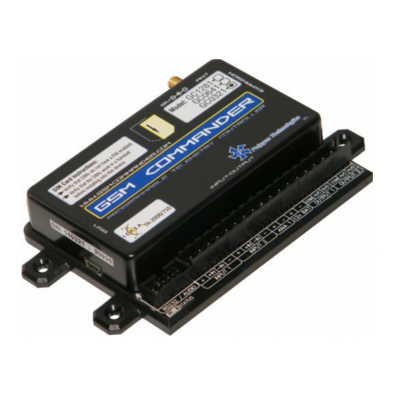
User Manual for
GC0321, GC0641, GC1281
Applicable to software package Version 7.47 and up
Last Edited 03 October 2017
Before Attempting to connect or operate this product, please read these instructions in its entirety
This manual is intended to provide detailed technical specifications and explanations, to the basic
user as well as the more technically-minded person. This manual is a live document, and will be
updated often with new information. Please insure that you have the latest version, by checking our
website at: https://www.gsmcommander.com.
Changelog:
DS 03 October 2017 - Fixed specification table error
DS 09 June 2017 - Update error codes and content
DS 09 May 2017 - Update content (antenna info)
DS 20 April 2017 - Update content / IMEI number
DS 04 April 2017 - Fix errors and update content
SD 30 September 2016: - Fixed errors and updated content
DS 25 August 2016: - Updated contents table, fix errors and update content
HM 15 June 2016: - Updated contents table with missing references,fixed spelling errors.
HM 14 June 2016: - Amended operating parameters and description of settings.
HM 01 June 2016: - Added new Airdrive SMS config command, variable population strings.
SJD 25 July 2014: - Corrected General Status Message format.
SJD 05 July 2014: - Updated General Status Message format.
Advertisement
Table of Contents

Related Manuals for GSM Commander GC0321

Summary of Contents for GSM Commander GC0321
- Page 1 User Manual for GC0321, GC0641, GC1281 Applicable to software package Version 7.47 and up Last Edited 03 October 2017 Before Attempting to connect or operate this product, please read these instructions in its entirety This manual is intended to provide detailed technical specifications and explanations, to the basic user as well as the more technically-minded person.
-
Page 2: Table Of Contents
Outputs....................13 Temperature Sensor..................14 Analog Input....................15 Battery Input.....................16 Internal Battery..................16 Expansion Unit...................17 Dimensions of Expansion Unit................18 Status LEDs....................19 Testing the GSM Commander................21 Commissioning Mode..................22 Configuration VIA PC..................23 Basics......................23 Software Tabs....................24 Numbers Tab List A and B................24 Messages Tab.....................24 Behaviour Statements Tab................24 Settings Tab....................25... - Page 3 GSM Commander setup software reports............54 GSM Commander setup software reports “Hardware not detected”......54 GSM Commander does not send any SMS messages / Error codes........55 GSM Commander does not display the Airtime value..........56 GSM Commander does not respond to Voice Calls..........56 Guarantee....................57...
-
Page 4: Features
1. FEATURES GC0321 12/12 YES* Single GC0321 12/12 YES* Single GC0641 22/22 128 127 Single GC0641 22/22 128 127 Single GC1281 32/32 128 128 127 Dual GC1281 32/32 128 128 127 Dual Matrix Feature Descriptions Model The code used to define between the various units functionality and capabilities... -
Page 5: Specifications
2. SPECIFICATIONS Weight 200 grams Dimensions 146.2 x 85,2 x 27 mm Power Supply 12-24V DC via DC Jack Power Consumption ~ 2.5W ~ 60mA at idle (no inputs or outputs active) Current Consumption Operating Temperature -30°C to +60°C Storage Temperature -30°C to +80°C Opto-isolated. -
Page 6: Dimensions
4. DIMENSIONS © Polygon Technologies. All rights reserved Page 6... -
Page 7: Installation
5. INSTALLATION 5.1. Environment Due to the make-up of the GSM Commander and it's electronics, we STRONGLY advise that it not be installed in close proximity to a variable speed drive or any other electrically noisy equipment. DO NOT install the GSM Commander into a metal enclosure unless an antenna is mounted on the outside of the enclosure. -
Page 8: Antenna
SIM card then becomes useless. It is strongly recommended that you configure the GSM Commander to send you an SMS every now and then (once or twice a week) so that your SIM card remains active on the network. - Page 9 Screen 1: Click Screen 2: It is recommended that you leave the install path at the default location. Click Screen 3: Click © Polygon Technologies. All rights reserved Page 9...
- Page 10 Screen 4: Installation is in progress. Screen 5: Installation has been completed successfully. Click Screen 6: Click © Polygon Technologies. All rights reserved Page 10...
-
Page 11: Mounting
5.7. Mounting The GSM Commander is housed in a very durable ABS casing which has 4 protruding tabs, which allows it to be mounted firmly to any surface by means of a screw. There is also a DIN-rail mounting kit available separately. - Page 12 20V – 40V DC 1K ohm The + and – terminals are connected to the input power supply of the GSM Commander. If the power supply is 14V, the voltage at the + and – terminals will be slightly less at about 13.8V (due to an internal series diode for reverse polarity protection).
-
Page 13: Outputs
GSM Commander. For each expansion unit, the same applies. 5.9. Outputs The GSM Commander itself provides 2 x 8A (DC) Relay outputs. The number of outputs can be expanded by the addition of Expansion modules, up to a maximum of 32 outputs*. Each of these inputs each have 3 terminals associated with them:. -
Page 14: Temperature Sensor
5.10. Temperature Sensor One can connect 2 temperature sensors to the GSM Commander (at the expansion port via a temperature interface module) to measure temperature and allow the GSM commander to perform certain tasks if the temperature falls above or below a certain point. The sensor provides an accuracy of 2°C. -
Page 15: Analog Input
0 litres, and leave the rest of the calculations to the GSM Commander. You can now receive a message from the GSM Commander, detailing the actual contents of the tank in litres, instead of just a raw value. (Which you would otherwise have had to convert back to “real”... -
Page 16: Battery Input
(Like sending an SMS and switching on emergency lighting) In cases where the GSM Commander is used in conjunction with a large system with its own battery (such as UPS systems), the battery terminals of the GSM Commander can be safely connected to the large (12V) battery, and the GSM Commander can then monitor the battery voltage for you (only while power is NOT supplied to the power input connector). -
Page 17: Expansion Unit
Now that it is almost impossible to turn the GSM Commander off, it may be a problem to reset it. To reset the GSM Commander, the "Turn-Off " dongle that is supplied with the unit must be inserted into the GSM Commander's RS232 port. -
Page 18: Dimensions Of Expansion Unit
Pin 2 connects to pin 9 etc. It is important to connect the Expansion port on the GSM Commander to the IN connection on the expansion unit. An additional Expansion unit must be connected with its IN connection to the OUT connection of the “upstream”... -
Page 19: Status Leds
5.16. Status LEDs The GSM Commander has 2 LEDs to show the current status of the GSM Commander. The red LED, labelled “GSM”, shows the status of the internal GSM cellular engine, while the green LED, labelled “STATUS”, shows the status of the GSM Commander as a whole. - Page 20 Applicable to units with SN:xxxxxx- xxxx: : GSM engine OFF ➢ on for 64ms, off for 800ms ➢ : GSM engine searching for network on for 64ms, off for 2000ms (1 short flash every 2 seconds) ➢ : GSM engine registered OK Applicable to units with SN:xxxxxx- xxxx: : GSM engine OFF...
-
Page 21: Testing The Gsm Commander
5.17. Testing the GSM Commander 5.17.1. Status Request The GSM Commander (even with a blank configuration) has a built-in test feature. If the GSM Commander receives “TEST GSMC” as an SMS message, it will reply to the number that sent the message, with the following text: DT=01/01/2017-12:00:00 <... -
Page 22: Commissioning Mode
5.18. Commissioning Mode This function was introduced in version 7.46 of the the SmartSetup software. Commissioning Mode is basically a TESTING mode without needing physical triggers. This is ideal for workshop testing, before going live. Examples what you can do: 1. -
Page 23: Configuration Via Pc
SIM card(s) (See sec 6.4) ➢ Please note: The GSM Commander will eventually startup if no SIM card is inserted, but there would be no GSM functionality, which means none of the GSM features will work. Follow these steps: Step 1:... -
Page 24: Software Tabs
6.2. Software Tabs The GSM Commander Setup Utility software has been designed to make the configuration process of the GSM Commander as easy and user-friendly as possibly. With this in mind the software has been divided into the following tabs: Numbers ➢... -
Page 25: Settings Tab
Asset ID String ➢ My number ➢ Special settings ➢ 6.2.5. Status Tab This tab allows the user to monitor the status of GSM Commander (while connected to PC) with regards to: Active SIM ➢ GSM Status ➢ GPRS Status ➢... -
Page 26: Io Names Tab
Please Note: These IO Name changes will be stored in the setup that is saved to file, but will ONLY be stored in the setup that is saved to the GSM Commander if enabled under Settings Tab. 6.2.7. Analog Scaling Tab This tab allows the user enable the Analog scaling functionality when an Analog Expansion Unit is connected to the GSM Commander. -
Page 27: Configuration Via Sms
This command can ONLY be sent from the administrator number(if one exists), otherwise it can be sent from any number . ADMIN SETADM 0831234567 This will store “0831234567” as the new administrator number. The GSM Commander will reply with a confirmation message. 7.2. Clear Administrator number This command can ONLY be sent from the administrator number. -
Page 28: Check Administrator Number
GSM Commander, the administrator must send: ADMIN STATEMENT 8 ON ADMIN STATEMENT 8 OFF This will either enable(ON) or disable(OFF) statement 8 respectively. The GSM Commander will reply with a confirmation message. © Polygon Technologies. All rights reserved... -
Page 29: Override Gprs Settings
7.8. Override GPRS Settings This set of commands allows you to override the GPRS settings that the GSM Commander may have been configured with and can only be sent from the administrator number. These override settings are volatile, which means their effect will not be retained after power has been recycled. -
Page 30: Imei Number
To switch from the currently active SIM card to the inactive SIM card you must send: SIMTOGGLE 7.13. Reset GSM Commander This command can be sent from ANY number. To reset the GSM Commander you must send: RESET GSMC © Polygon Technologies. All rights reserved... -
Page 31: If-Then Behaviour Statements
8. IF-THEN BEHAVIOUR STATEMENTS The GSM Commander is configured by defining a number of behaviour statements. Each statement takes the form of an IF-THEN pair. You are thus able to select certain trigger conditions that will cause desired actions to be performed. Any combination of IF and THEN parts can be assembled into complete statements using the configuration software. - Page 32 If the “Stay on” call option is selected, the GSM Commander will hold the call until the caller ends the call.
- Page 33 8.1.4. IF Output This trigger condition is very similar to “IF Input”, as it monitors and output instead of an input. 8.1.5. IF Logic Expression A statement containing this IF condition, will trigger if the specified logic conditions are met. This allows the user to specify interesting combinations, like input 1 AND input 2 must be active before action is taken.
- Page 34 To use this option, you need to have a temperature probe connected to the expansion port of the GSM Commander via a temperature interface module. Also make sure that the correct type of probe is selected in the “Temperature Probe Configuration” box under the “Settings” tab in the software.
- Page 35 The GSM Commander will check the prepaid airtime balance from time to time, and the statement will trigger if the balance is below the selected threshold.
- Page 36 A statement containing this IF condition, will trigger if a RFID tag is scanned via a Stealth RFID Reader 125KHz antenna (Product Code: GA100) that is fitted to the GSM Commander. The user can choose between the same six options as listed under “IF Voice Call is Received”...
-
Page 37: Supported Then Actions
8.2. Supported THEN Actions 8.2.1. THEN Change Output A statement containing this Action, will change the selected output according to specified actions. The user can choose between the following five actions: • Activate for a time • Activate for a time – Pause – Activate for a time •... - Page 38 GPRS to our server to update the status of the ➢ “Log Status to Server”, GSM Commander on the AirDrive platform. (Log onto Airdrive to find out more) The recipient number can be defined in one of the following six ways: •...
-
Page 39: Multiple Actions To A Single If Condition
SMS as well. The GSM Commander will always execute all statements that are eligible to trigger due to a certain event, in other words, the first statement that is triggered, does not void or “eat up” the event. -
Page 40: Message Parameters
10. MESSAGE PARAMETERS The GSM Commander support the use of parameters in predefined messages. This allows the user to insert and refer to certain values in message. \t – Current time (HH:MM:SS) \n – Line Feed (0x0A) ➢ ➢ \d – Current date (DD/MM/YYYY) \$ - Asset ID ➢... -
Page 41: Variables
The GSM Commander can also be configured to trigger a statement at a certain time on a certain date or group of days. -
Page 42: Prepaid Airtime Voucher Loading
“141” is network-dependent, and the 0000000000000 is the voucher number. This detail is typically provided on the voucher slip. To send a voucher to the GSM Commander, you simply send it an SMS of the form : SENDUSD:*141*000000000000# ( from any number) where 000000000000 is the voucher number. -
Page 43: Rs232 Configuration
All configuration messages ARE case sensitive. 14.2.1. SMS Sending The user can send an SMS message directly from the GSM Commander by sending the following: *SMSTX:0831231234:This is the message# Where “0831231234” is the recipient number, and “This is the message” is the message to be sent. - Page 44 14.2.3. GPRS Message Sending ( Only available on the 0641 and 1281 models) The user can send a GPRS message directly from the GSM Commander by sending the following: *GPRSTX1:This is the message# Where “This is the message” is the message to be sent to the connected server.
- Page 45 14.2.6. Clear GPRS Queue The user can request the GSM Commander to clear the GPRS queue via the serial port by sending the following: *CLEARQ2# The GSM Commander will reply with FLUSH GPRS if the instruction is successfully received. 14.2.7. Accessing Inputs and Outputs The user can change outputs and read inputs via the the Serial Port.
- Page 46 14.2.10. Check Airtime The user can request the GSM Commander to check current airtime via the serial port by sending the following: *ATCHECK# The GSM Commander will request the airtime balance from the network and reply with AT=xx (where xx is the current airtime value) Please Note: The airtime remaining will be displayed as “AT=--”...
-
Page 47: Firmware Updates
Run the Utility (Start > All Programs [ALL APPS]> GSM Commander V7 > Update Firmware) The SmartSetup software will also automatically detect upon startup if the firmware currently loaded on the GSM Commander unit does not match it's current version. It will then prompt you to run the update firmware utility. -
Page 48: Low Power / Battery Operation
16. LOW POWER / BATTERY OPERATION By the use of current limiting resistors on the inputs of the GSM Commander and Expansion Units, the GSM Commander can operate more efficiently in terms of current consumption. This is particularly important when the GSM Commander is powered by means of a battery connected to a solar panel or any other alternative source of power generation. -
Page 49: 4-20Ma Analog Application Note
Goal:To connect a 4-20mA sensor to your GSM Commander. GSM Commander Wiring: Connect a wire from the (+) terminal(14V) of any Input from the GSM Commander to the supply voltage input of the sensor. Then connect a wire from the output(4-20mA) of the sensor to the (+) terminal of the Analog Input. -
Page 50: Special Settings
Special setting can be found in SmartSetup software. This enabled or disable advanced functions on the GSM Commander. Some function is explained below. New functions will be added from time to time. Please click on the What is this? Button for up to date descriptions You just enter the characters in the special setting box. -
Page 51: Application Examples
The second statement will cause a notification SMS to be sent to both +27821231234 and +27843214321. This is an example of how the GSM Commander can have multiple actions triggered by a single event (in this case, an input becoming active). Note that the voice call will not “say” anything when the call is answered. -
Page 52: Example 3: Control An Appliance
In this example we need to switch a 220V light bulb on or off via a suitable SMS message from a specific number listed on the GSM Commander. Hardware: We connect light bulb to a 220V power source via the output 1 contact on the GSM commander, exactly as described in section 6.9 Configuration: Using the setup software, we create a behaviour statement that will read as follows: IF Message is received, containing “Lights on”... -
Page 53: Example 5: Contact To Contact Relay
We use a second GSM commander unit at the remote location. Here we connect the warning light to output 1 of the GSM Commander so that if the relay is activated, the warning light will turn on. (exactly as described in section 6.9) Remote GSM Commander configuration: The configuration of the remote unit will be similar to example 2 (control an appliance). -
Page 54: Troubleshooting
Cause 2: GSM Commander not connected via USB Cause 3: GSM Commander USB drivers not installed. It is a good idea to disconnect all cables from the GSM Commander, and then reconnecting everything (power and USB cable). If the problem persists, please follow this procedure to verify... -
Page 55: Gsm Commander Does Not Send Any Sms Messages / Error Codes
If this item is not present, the drivers are not installed correctly. To install your drivers, go to C:\Program Files\GSM Commander V7\drivers\drv_install and run “GSMC_USBXpressInstaller.exe or run “Reinstall drivers” (Start > All Programs [ALL APPS] > GSM Commander V7 > Reinstall drivers) . This will install your drivers. -
Page 56: Gsm Commander Does Not Display The Airtime Value
Three will trip if we have not queried the GSM module for received SMSes in a while. 20.4. GSM Commander does not display the Airtime value Cause 1: Incorrect operator selection You may have chosen the incorrect operator settings under the “SETTINGS TAB” in the software interface. -
Page 57: Guarantee
Disclosure of Product limitations / known issues The GSM Commander is a reliable product and we have many thousands of units sold and used in all sorts of different applications. That being said, there are limitations to what it can do, and to the applications where it's use is appropriate. -
Page 58: Manufacturer Contact Details
5 000 units per year) Logic functions The GSM Commander has some functionality that reminds one of a PLC. This is true, but the GSM Commander is NOT a PLC, and if you are an automation engineer, some of the limitations will tend to annoy.
Need help?
Do you have a question about the GC0321 and is the answer not in the manual?
Questions and answers
Commander sends high temp readings, probes are placed in liquid in fridges. temps readings are above 800 degrees Celsius
The GSM Commander GC0321 may be showing high temperature readings above 800°C when probes are placed in liquid in fridges due to incorrect scaling or misinterpretation of the analog signal. The document states that a 20mA output signal corresponds to 94°C. If the software is not correctly configured to interpret the signal within the expected range, it may display extreme values. Adjusting the temperature reading conversion in the Setup Software may resolve this issue.
This answer is automatically generated