Advertisement
USER GUIDE
Order No.:
8069
LRP electronic
Wilhelm-Enssle-Str. 132-134, 73630 Remshalden, Germany
Tel.: int+49-71 81-40 98-0, Fax: int+49-71 81-40 98-30
http: //www.lrp-electronic.de
!
WARNING NOTES
• Important: never leave your RC model unattended when the
battery is connected. If a fault should occur the result could be a
fire in the model which could destroy anything else in the vicinity.
• The speed control and other electronic components must never
be allowed to contact water. Avoid operating the unit in rain. If
you are obliged to run in wet conditions, domestic paper towels
provide the best protection.
• If the motor is connected to the speed control you must not run
the motor by connecting a separate battery. This will wreck the
unit and invalidate the guarantee.
• Take care to avoid incorrect connections and reverse polarity as
INSTALLATION TIPS
• Mount the speed control in the model using the double-sided foam tape supplied.
• Provide plenty of cooling openings in the bodywork; this increases the performance and extends the
life of all electronic components.
• Install the speed control in a location where it is protected from crash damage.
• The speed control should be installed in such a way that you have easy access to all connectors and
the set-up button.
• Ensure that there is an adequate distance (approx. 3 cm) between the speed control and power cables
and the receiver or receiver aerial. Avoid direct contact between all power system components and the
receiver or aerial, as this can cause interference. If you encounter interference problems, re-position
the components in the model.
• The aerial should be run vertically up and away from the receiver. Avoid contact with any parts made
of carbon fibre or metal. If the aerial is too long, don't coil up the excess length. It is better to cut it
down to a length of about 35 cm. See also the instructions supplied with your radio control system.
• Use the sheet of stickers supplied to protect your speed control from dirt and dust, and to hold the
case together so that it cannot come apart in a serious collision or when heavily stressed. Carefully
remove all traces of grease and dirt from your speed control (don't use motor cleaners or similar
agents), then apply the sticker round the outside of the case. If necessary you can also apply the dust guard.
• IMPORTANT: Heat-sink (included in set): the heat-sinks supplied are not absolutely essential, but can
reduce the speed control's temperature under extreme conditions. It is vital to ensure that the two
heat-sinks are well separated from each other, and cannot touch. A short-circuit between the two may
ruin your speed control.
INSTALLATION
• Solder the suppressor capacitors and the Schottky diode to the motor.
• Remove the motor pinion, or ensure in some other way that the wheels of the model can rotate freely.
• Install the speed control in the model.
• Solder the connectors to the thick power cables (not included).
• The switch must be set to OFF when you do this.
• Connect the speed control to the receiver (channel 2).
• If you are using a servo with an external FET cable, solder this connection now.
• Connect the speed control to the motor: red wire to positive (+), blue wire to negative (-).
• Check all the wiring and connections before you connect the speed control to a drive battery.
Caution: incorrect polarity will wreck your speed control.
• The speed control is now ready to be set-up (see next page).
Dear customer,
Many thanks for placing your trust in the IPC-V7.1. This is a new development based on the legendary IPC-V6 World
Champion's speed control, and incorporates the latest findings in the field of speed control technology:
• New 7.1 software
• Longer running times
• More power
• More powerful, more constant braking
• Can be used with four cells without receiver battery
• Superior initial acceleration
• Programmable automatic brake
• 3140 Hz digital pulse frequency for optimum control
SPECIFICATION
Voltage range / No. of cells
4.8-9.6 V/4-8
Voltage range without BEC
4.8-12 V/4-10
Internal resistance
0.00052
Momentary load (1 sec)*
690 A
Brief load (30 sec)
165 A
Continuous load (5 min)
100 A
Recommended motor
No limit
Receiver voltage
6.0 V
Max. receiver current (30 sec) 3.0 A
* The reading „Momentary load (1sec)" is equal to US-manufacturers reading „continuous load at 25°C"
this will also cause damage to the unit. If you prefer different
connectors, fit a polarised connector system (plugs / sockets)
such as the LRP Hi-Amp (No. 6280); this does not invalidate your
guarantee.
• Never allow the output stages (FETs) to touch a metal surface
- short-circuit hazard.
• Never wrap your speed control in foil or film; air must always be
able to flow round and over the unit.
• All cables and connections should be well insulated.
Short-circuits will ruin the unit.
• Never change the polarity of the receiver plug.
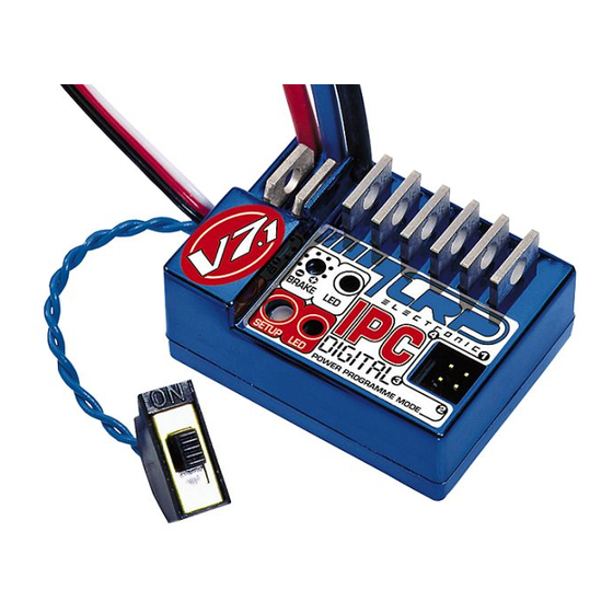
CONNECTIONS
Blue-negative (-M) motor
Red-positive (+M) motor
Red-positive (+B) battery
Black-negative (-B) battery
FET servo wire
On/Off switch
3-colour ribbon cable - receiver lead
• Graupner, Ko-Propo, Futaba, Hitec and LRP Phaser receivers:
The LRP speed control is fitted with an LRP Multi-Con receiver lead which fits any of the above
receivers directly.
• Sanwa receivers:
Remove the black plastic moulding from the receiver cable and replace it with the plastic moulding
supplied (inscribed "AIR") as follows:
• Replacing the plastic plug moulding:
Press in the metal lugs of the connector pins using a ball-point pen to disengage them; the wires can
then be withdrawn from the plastic housing. Check the polarity using the table below, and slip the
pins into the new plastic moulding until they snap into place.
Bend the metal lugs up again.
Push the plug into the new plastic moulding.
Check correct polarity carefully if changing connectors:
Receiver
Futaba
Graupner
Signal wire
white
orange
Positive wire
red
red
Negative wire
black
brown
SUPPRESSING THE MOTOR:
The Schottky diode improves the efficiency of the speed control / motor combination, and provides
additional protection to the brake FETs. Solder the diode in place as shown in the illustration. Note that
the white ring must always face the positive motor terminal.
Caution: Schottky diodes may only be used with pure
!
forward/brake speed controls!
• Reactive Throttle Control - software provides fine,
sensitive speed control
• Acceleration-Plus circuitry - new circuit technology
for more power and lower current drain
• Blue super-shielded case
• Active current limiting
• Single-button set-up
Continuous receiver current (5 min) 1.2 A
Pulse frequency
3140 Hz
Brake adj. + Auto.Brake
EMF
Current Limiter
Digital
Startautomatic
yes
Power-on pulse suppression
yes
Single-button
Weight
42 g
Size
43x34x19 mm
Acoms
Sanwa
yellow
yellow
red
red
black
black
Schottky diode:
Advertisement
Table of Contents

Related Manuals for LRP IPC-V7.1

Summary of Contents for LRP IPC-V7.1
- Page 1 Dear customer, Many thanks for placing your trust in the IPC-V7.1. This is a new development based on the legendary IPC-V6 World Champion’s speed control, and incorporates the latest findings in the field of speed control technology: • New 7.1 software •...
- Page 2 AUTOMATIC START CIRCUIT: The IPC-V7.1 automatic start circuit gives you a crucial advantage at the start of a race. In this mode the response time of in the unit even when the speed control is subsequently disconnected from the battery.
Need help?
Do you have a question about the IPC-V7.1 and is the answer not in the manual?
Questions and answers