
Related Manuals for AC Fire Pump 8100 series

Summary of Contents for AC Fire Pump 8100 series
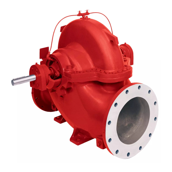
- Page 1 INSTRUCTION MANUAL AC2515 REVISION E INSTALLER: PLEASE LEAVE THIS MANUAL FOR THE OWNER’S USE. 8100 Series Centrifugal Pumps...
-
Page 2: Table Of Contents
SHUTDOWN ..........21 installation, operation, and maintenance of this FREEZE PROTECTION......21 equipment. FIELD TESTS..........22 Any further questions, contact AC Fire Pump, MAINTENANCE..........23 (847) 966-3700. GENERAL MAINTENANCE AND PERIODIC INSPECTION........23 MAINTENANCE OF FLOOD DAMAGED PUMPS ..........23 LUBRICATION ..........23... -
Page 3: Introduction
INTRODUCTION We welcome you as a user of AC Fire Pump. Your rating plate to identify the pump in his operation. pump is a product of careful engineering and (e.g. CWP-11 stands for Chilled Water Pump No. skilled workmanship. We believe you have the best pump possible for the service intended. -
Page 4: Safety Instruction
SAFETY INSTRUCTION The warning and caution decals located on the pump are there for the safety of anyone involved with the installation, operation, and maintenance of the pump. PLEASE READ THE DECALS CAREFULLY. SAFETY INSTRUCTION This safety alert symbol will be used in this manual and on the pump safety instruction decals to draw attention to safety related instructions. -
Page 5: Installation
INSTALLATION RECEIVING THE PUMP NYLON SLING, Check the pump for damage immediately upon CHAIN OR WIRE arrival. (An absolute must!) Prompt reporting of ROPE any damage to the carrier’s agent, with notations made on the freight bill, will expedite satisfactory adjustment by the carrier. - Page 6 Using ANSI/OSHA Standard “S” hooks, or wire rope using latch hook or standard place the “S” hooks in the holes provided shackle and end loop. in the four corners of the base. Be sure the points of the hooks do not touch the bottom of the pump base.
-
Page 7: Storage
Cortec Corp. VCI-329 (for both grease and oil lubricated bearings). Seal all vents and apply NYLON SLING, a water proof tape around the oil seals in the CHAIN, OR 30º WIRE ROPE bearing frame. Remember for pumps with oil lubricated bearings to drain the oil from the frame and refill to the proper level before running the pump. -
Page 8: Base Plate Setting (Before Piping)
If alignment needs improvement, add motor is to be field mounted, consult factory for shims or wedges at appropriate positions recommendations. AC Fire Pump CANNOT assume under base, so that retightening of anchor responsibility for final alignment. nuts will shift shafts into closer alignment. -
Page 9: Grouting Procedure
piping to pump. (24 hours is sufficient time dried thoroughly according to instructions. Final with approved grouting procedure.) alignment should be made by shimming driver only. Alignment should be made at operating temperatures. GROUTING PROCEDURE Grout compensates for uneven foundation, WARNING: Unexpected Start-up Hazard distributes weight of unit, and prevents shifting. - Page 10 Holding the guard in this position, tighten remaining capscrews. the three capscrews. ANSI/OSHA Coupling Guard Exploded View For Typical 8100 Series Fire Pump Installation INNER GUARD OUTER GUARD ATTACH SUPPORT BRACKET TO BEARING HOUSING...
- Page 11 i. For single element couplings, a satisfactory parallel misalignment is STRAIGHT EDGE .004"T.I.R., while a satisfactory angular misalignment is .004"T.I.R. per inch of radius R (See Figure 10B). FEELER GAGE PARALLEL DIAL ANGULAR ALIGNMENT PARALLEL ALIGNMENT INDICATOR ALIGNMENT INCORRECT ALIGNMENT STRAIGHT EDGE INDEX LINE RESILIENT...
- Page 12 should be roughly equal to the shaft misalignment, strike the side of the motor diameter. foot with a mallet. 5. Tighten setscrews. 11. Tighten the motor bolts and check again. If a correction is made, re-check alignment 6. Bring the pump and motor halves of the in all directions.
- Page 13 gaskets stay in position during fastener tightening. FIGURE 10G – COVER INSTALLATION, VERTICAL POSITION 17. Ensure the lube plugs are installed in the cover. WARNING: Coupling Failure FIGURE 10F – COVER INSTALLATION Do not operate coupling without proper lubrication 16. If the shafts are not horizontal, or coupling Failure to follow these instructions could result in is to be used vertically, assemble cover serious personal injury or death and property...
-
Page 14: Doweling
OPTIONAL Alignment Procedure Final Alignment If desired, the pump and motor feet can be Final alignment cannot be accomplished until doweled to the base after final alignment is the pump has been operated initially for a complete. This should not be done until the sufficient length of time to attain operating unit has been run for a sufficient length of temperature. -
Page 15: Suction And Discharge Piping
Make sure that all piping joints are air-tight. SUCTION AND DISCHARGE PIPING Where flanged joints are used, assure that inside The introduction of a pump into a piping system diameters match properly. which is not well designed or adjusted may cause strain on the pump, leading to misalignment or Remove burrs and sharp edges when making up even impeller rubbing. - Page 16 WATER VELOCITY INCREASES CASING HERE, CAUSING A GREATER RINGS FLOW TO ONE SIDE OF THE PUMP CASING IMPELLER PUMP SUCTION IMPELLER FLANGE SUCTION ELBOW FIGURE 12 – UNBALANCED LOADING OF A DOUBLE SUCTION IMPELLER DUE TO UNEVEN FLOW AROUND AN ELBOW ADJACENT TO THE PUMP Eccentric reducers should be limited to one 2.
-
Page 17: Stuffing Box Lubrication
Discharge Piping CHECK VALVE If the discharge piping is short, the pipe GATE VALVE SUCTION PIPE INSTALLED diameter can be the same as the discharge WITH A GRADUAL RISE TO PUMP INCREASER opening. If the piping is long, the pipe LEVEL diameter should be one or two sizes larger than the discharge opening. - Page 18 difficult. Consideration should be given to using a Only a sufficient volume of sealing liquid to create mechanical seal. (See Mechanical Seals.) a definite direction of flow from the stuffing box inward to the pump casing is required, but the pressure is important.
- Page 19 The change from packing to an alternate arrangement may be made in the field by competent service personnel. Conversion parts may be order from your AC Fire Pump Sales Representative. Just as with packing, the mechanical seal chamber must be supplied, at all times, with a source of clean, clear liquid to flush and lubricate the seal.
-
Page 20: Operation
OPERATION each time the motor leads have been PRE-START CHECKS disconnected. WARNING: Unexpected Startup Hazard Disconnect and lockout power before PRIMING servicing. Failure to follow these instructions could If the pump is installed with a positive head on the result in serious personal injury or death, or suction, it can be primed by opening the suction property damage. -
Page 21: Starting
the anchors and supports are not adequate or 4. Temperature: Check and record bearing set properly and should be corrected. temperatures using a thermometer. Temperature should not exceed 180°F. STARTING 5. Vibration and Sound: The acceptable 1. Close drain valves and valve in discharge vibration level of a centrifugal pump line. -
Page 22: Field Tests
150°F. FIELD TESTS A typical performance curve for a specific pump can be obtained from AC Fire Pump. This can be used in conjunction with a field test, if one is required. All AC Fire Pump tests and curves are based on the Hydraulic Institute Standards. -
Page 23: Maintenance
MAINTENANCE Next, inspect the stuffing box, and clean out any foreign GENERAL MAINTENANCE AND matter that might clog the box. Packing that appears to PERIODIC INSPECTION be worn, or no longer regulates leakage properly should Operating conditions vary so widely that to be replaced. - Page 24 Shell Gadus® S5 T100 2 ExxonMobil Unirex™ N2 Oil Lubrication of Bearings Oil lubrication on 8100 Series pumps is considered special. Oil lubricated pumps are installed with Trico oilers (See Figure 15). The oilers keep the oil level in the housings constant.
-
Page 25: Seal Information
NOTE: Oils from different suppliers should before pump is started. not be mixed. Engine oils are not The standard 8100 series pump packing is recommended. made from braided acrylic yarn impregnated The oil should be a non-foaming, well refined, with graphite. - Page 26 or sleeve for possible scoring or eccentricity, c. A mechanical seal which has been used make replacements where necessary. should not be put back into service until the sealing faces have been replaced or New packing (non-asbestos) should be relapped. (Relapping is generally placed carefully into the stuffing box.
-
Page 27: Maintenance Time Table
MAINTENANCE TIME TABLE EVERY MONTH Check bearing temperature with a thermometer, not by hand. If bearings are running hot (over 180°F), it may be the result of too much lubricant. If changing the lubricant does not correct the condition, disassembly and inspect the bearings. Lip seals bearing on the shaft may also cause the housing to run hot. -
Page 28: Trouble Shooting
TROUBLE SHOOTING Between regular maintenance inspections, be alert for signs of motor or pump trouble. Common symptoms are listed below. Correct any trouble immediately and AVOID COSTLY REPAIR AND SHUTDOWN. CAUSES CURES No Liquid Delivered 1. Lack of prime. Fill pump and suction pipe completely with liquid. 2. -
Page 29: Trouble Shooting (Cont.)
TROUBLE SHOOTING (cont.) Causes Cures 16. Impeller partially plugged. See item 9. 17. Cavitation; insufficient a. Increase positive suction head on pump by lowering pump or NPSHA (Net Positive increasing suction pipe and fittings size. Suction Head Available). b. Sub-cool suction piping at inlet to lower entering liquid temperature. c. - Page 30 TROUBLE SHOOTING (cont.) Causes Cures Pump Operates For Short Time, Then Stops 30. Insufficient NPSHA. See item 17. 31. System head too high. See items 4 and 10. Pump Takes Too Much Power 32. Head lower than rating; Machine impeller’s O.D. to size advised by factory or reduce speed. thereby pumping too much liquid.
-
Page 31: Service
8100 Series pump construction. serious personal injury or death, or property damage. A. 8100 Series pump with packing. B. 8100 Series pump with mechanical seals WARNING: Rotating Components on shaft. Hazard Do not operate pump without all guards in place. - Page 32 CW ROTATION CWW ROTATION SUCTION DISCHARGE DISCHARGE CLOCKWISE ROTATION VIEWED COUNTER-CLOCKWISE ROTATION FROM THE COUPLING END VIEWED FROM THE COUPLING END FIGURE 16 – CORRECT RELATIONSHIP OF IMPELLER AND CASING DOWEL PIN LOCATION AT PARTING LINE OPTIONAL – INTERNAL PIPING WITH SEAL CAGE PUMP SIZE DIM.
-
Page 33: Dismantling (Pump With Packing)
A. DISMANTLING (PUMP WITH PACKING) WARNING: Unexpected Start-up Hazard Disconnect and lock out power before servicing. Failure to follow these instructions could result in serious personal injury or death, or property damage. WARNING: Electrical Shock Hazard Electrical connections to be made by a qualified electrician in accordance with all applicable codes, ordinances, and good practices. -
Page 34: Assembly (Pump With Packing)
(3-009-9) (0-004-0) (3-003-9) SLEEVE IMPELLER RING CASING RING FIGURE 20 – REMOVING STUFFING BOX 11. Loosen set screws (3-902-3) in shaft nuts (3-015-9) and then remove shaft nuts using pin scanner wrench. Remove O- rings (3-914-9) from counterbore in shaft CASING LOCKING PIN IMPELLER... - Page 35 the gasket, lightly tapping with a ball peen hammer so that it is flush with the inside edges of the casing. NOTE: Precut casing gaskets (2-153-5 & 6) can be ordered to minimize the amount of trimming. 1. Assemble the impeller key (3-911-1) in the shaft key slot.
- Page 36 15. Install lockwasher (3-517-4) and locknut (3-516-4) on the outboard end of the shaft. Make certain locknut is secured and then bend over tabs on lockwasher. 16. Allow the bearing to cool to room temperature. On grease lubricated bearings only, coat the exposed sides with two or three ounces of recommended grease.
-
Page 37: Optional Method For Installing Packing (After Pump Disassembly)
26. PACKING (NON ASBESTOS) Install 12 full rings of packing (6 per stuffing box) so that the ends butt, leaving no gap between the packing and the stuffing box. (Refer to the table in Figure 17 for packing size.) Press the packing to the bottom of the stuffing box. -
Page 38: Dismantling (Pump With Mechanical Seals On Shaft)
DOWEL PIN LOCATION AT PARTING LINE FIGURE 27 – ASSEMBLY SECTION: PUMP WITH MECHANICAL SEALS ON SHAFT CAUTION: Extreme Temperature Hazard B. DISMANTLING (PUMP WITH MECHANICAL Allow pump temperatures to reach SEALS ON SHAFT) acceptable levels before proceeding. Open drain WARNING: Unexpected Startup Hazard valve. - Page 39 4) from the shaft. Remove the inboard end WARNING: bearing (3-026-3) in the same manner. Prior to working on pump the power source should be disconnected with lockout provisions so power cannot be re-energized to the motor. Close isolating suction and discharge valves. Failure to follow these instructions could result in property damage, severe personal injury, or death.
-
Page 40: Assembly (Pump With Mechanical Seals On Shaft)
(3-009-9) (0-004-0) (3-003-9) SLEEVE IMPELLER RING CASING RING FIGURE 31 – REMOVING CASING RINGS FROM IMPELLER CASING LOCKING PIN IMPELLER 10. Remove mechanical seal head (3-402-0) (2-001-0) (3-943-9) (4-002-0) from the pump shaft. FIGURE 33 –IMPELLER WITH WEAR RINGS 11. Remove two casing rings (3-003-9) from the impeller (4-002-0) and remove O-rings (3-914-2) from each casing ring (See 13. - Page 41 lubricate the seal lip with a lightweight oil. NOTE: Lip seals should seat against machined shoulder bracket. NOTE: Seal lip should point away from the bearings (3-026-3 and -4), if the bearings are grease lubricated, and towards the bearings, if the bearings are oil lubricated. 8.
- Page 42 NOTE: A locknut and lockwasher are not CAUTION: installed on the inboard end of the shaft. DO NOT EXCEED 275°F. 18. Clean the gasket surfaces of the casing. 12. Heat the ball bearing (3-026-4), using Apply Scotch 3M-77 spray adhesive or either dry heat or a 10-15% soluble oil and equivalent to the lower half of the casing.
-
Page 43: Dismantling (Pump With Mechanical Seals On Shaft Sleeves)
DOWEL PIN LOCATION AT PARTING LINE SETTING DIMENSIONS PUMP SIZE TYPE 1 TYPE 21 MECH TYPE 1B MECH IMPELLER MECH. SEAL LOCATION SEAL SEAL (STANDARD) DIMENSIONS “A” “B” “A” “B” “A” “B” “C” 3x2x11 6.62 6.75 6.00 6.12 7.00 7.12 8.755 6x4x9 9.312... - Page 44 2. Remove all casing main joint cap screws NOTE: Locknut and lockwasher are not used (2-904-1) and dowels (2-916-1). Remove on inboard end bearing. external tubing (0-952-0) if supplied. CAUTION: 3. Insert a screwdriver or pry bar into the DO NOT REUSE THE BALL BEARINGS. slots between the upper and lower casing halves, and separate the halves, lifting off 7.
-
Page 45: Assembly (Pump With Mechanical Seals On Shaft Sleeves)
15. Remove the impeller key (3-911-1) from the shaft. ASSEMBLY (PUMP WITH MECHANICAL SEALS ON SHAFT SLEEVES) All bearings, O-rings, lip seals, mechanical seals, gaskets, impeller rings, and casing rings should be replaced with new parts during assembly. All reusable parts should be cleaned of all foreign matter before reassembling. - Page 46 tighten the shaft sleeve nuts. Then drill a 3/16" diameter shallow recess in the shaft through the set screw hole in each of the shaft sleeve nuts. Lock each shaft sleeve nut in position with set screws (3-902-3). A low strength sealant, such as Loctite 271, can be used to retain set screws (See Figure 45).
- Page 47 NOTE: A locknut and lockwasher are not 15. Slide outboard end of stuff box on the installed on the inboard end of the shaft. shaft so that the shaft end extends 23. Clean the gasket surfaces of the casing. through the mechanical seal area, but Apply Scotch 3M-77 spray adhesive or does not enter the lip seal.
-
Page 48: Adjustable Wear Rings
Rotate the inner rings clockwise to restore .005"-.008" clearance greater than shaft end float between the ring and the impeller. Drill a new hole in the inner ring for the locking pin. This is a blind hole – do not drill through. Replace the locking pin and upper half casing. -
Page 49: Vertical Units (Models 200, 250, 300)
8. Fill the reservoir with a food grade of filtered mineral oil. Refer to oil lubrication RESERVOIR instructions given previously in this VENT manual for type of oil. ASSEMBLY THUMB NOTE: You must fill through Trico reservoir. BEARING SCREW HOUSING LEVEL 9. - Page 50 2. Remove the larger of the two pipe plugs from the top of the casing upper half and install an 18" to 24" solid bar threaded at one end into the exposed tapped hole. If a threaded bar is not available, it is permissible to use a standard pipe.
- Page 51 on floor with shaft in an horizontal position (See Figure 58). LOWER Rotate Main Joint Flange FIGURE 56 – UPPER HALF REMOVAL SLIDE ROTATE 11. Rotating element is now ready for FIGURE 58 – LOWER ROTATING ELEMENT inspection or removal. If element is inspected and does not need to be 18.
-
Page 52: Instructions For Ordering Parts52
Should it be necessary to remove a complete When ordering parts for 8100 pumps, be sure to pump, it will be necessary to remove the line furnish the following information to the AC Fire Pump shafting or motor, disconnect the pedestal stocking distributor in your area:... -
Page 53: Appendix "A" Engineering Data
APPENDIX “A” ENGINEERING DATA Pump Size 3x2x11S 3x2x1L 6x4x9 6x4x10S 6x4x10M 6x4x10L 6x4x10XL 6x4x11 6x4x12S 6x4x12M CASING DATA (All Dimensions in Inches) 125# FF Std Max. Suction Pressure ASA Flanges Max. Working Pressure NOMINAL 175 PSI Max. Hydrostatic Test Pressure Working Press. - Page 54 APPENDIX “A” ENGINEERING DATA Pump Size 6x4x12L 6x4x12XL 6x4x14S 6x4x14L 6x6x9 8x6x9 8x6x10 8x6x12S 8x6x12M 8x6x12L 8x6x12XL CASING DATA (All Dimensions in Inches) 125# FF Std Max. Suction Pressure ASA Flanges Max. Working Pressure NOMINAL 175 PSI Max. Hydrostatic Test Pressure Working Press.
- Page 55 APPENDIX “A” ENGINEERING DATA Pump Size 8x6x13 8x6x17M 8x6x17L 8x6x18 8x8x12 8x8x17 10x8x12S 10x8x12L 10x8x17S 10x8x17L 10x8x20S CASING DATA (All Dimensions in Inches) 125# FF Std Max. Suction Pressure ASA Flanges Max. Working Pressure NOMINAL 175 PSI Max. Hydrostatic Test Pressure Working Press.
- Page 56 APPENDIX “A” ENGINEERING DATA Pump Size 10x8x20L 10x10x12 12x10x12 12x10x12XL 12x10x14 12x10x17 12x10x18 CASING DATA (All Dimensions in Inches) 125# FF Std Max. Suction Pressure ASA Flanges Max. Working Pressure NOMINAL 175 PSI Max. Hydrostatic Test Pressure Working Press. Casing material Cast I Cast I Cast I...
-
Page 57: Explosion View: Packing
APPENDIX “B” EXPLOSION VIEW: PACKING OPTIONAL OPTIONAL OPTIONAL OPTIONAL OPTIONAL OPTIONAL OPTIONAL SEAL CAGE OPTIONAL OPTIONAL SEAL CAGE... -
Page 58: Explosion View: Mechanical Seals On Shaft
APPENDIX “B” EXPLOSION VIEW: MECHANICAL SEALS ON SHAFT... -
Page 59: Explosion View: Mechanical Seals On Shaft Sleeves
APPENDIX “B” EXPLOSION VIEW: MECHANICAL SEALS ON SHAFT SLEEVES (Set Collar-Slides Over 3-015-9 and 3-009-9) -
Page 60: Replacement Parts List
APPENDIX “B” REPLACEMENT PARTS LIST Quantity Part Number Part Name Packing Mech. Seal on Mech. Seal on Sleeve Shaft 0-400-0* Mechanical Seal 0-910-0 Pipe Plug (Casing) 0-912-0 Pipe Fitting 3 (optional) 0-944-0 Spirol Pin (Shaft Sleeve) 0-950-0 Pipe Nipple 2 (optional) 0-952-0 Tubing &... -
Page 61: Appendix "C" Field Test Report
APPENDIX “C” FIELD TEST REPORT... -
Page 62: Useful Formulas
APPENDIX “C” FIELD TEST REPORT USEFUL FORMULAS Pressure (psig.) 2.31 1) Head (ft.) = S.G. = specific gravity ; S.G. of water = 1.0 at 70°F S.G. 2) TDH (ft.) = Total Dynamic Head (ft.) = (Disch. pressure gauge reading - Suct. pressure gauge reading) + (Discharge velocity head - Suction velocity head) + (Elevation correction to disch. - Page 63 Xylem 1) The tissue in plants that brings water upward from the roots; 2) a leading global water technology company. We’re a global team unified in a common purpose: creating advanced technology solutions to the world’s water challenges. Developing new technologies that will improve the way water is used, conserved, and re-used in the future is central to our work.
Need help?
Do you have a question about the 8100 series and is the answer not in the manual?
Questions and answers