Table of Contents
Advertisement
Thank you for choosing TCI® products; we are proud to be your manufacturer of choice. Please read
this instruction sheet carefully before beginning installation, and also take a moment to review the
included limited warranty information.
System Components Overview
The EZ-TCU™ system is made up of several main components. A TCU (Transmission Control Unit),
a wiring harness, a handheld user interface, and an RPM module. Please read through all of the
installation notes before beginning the installation.
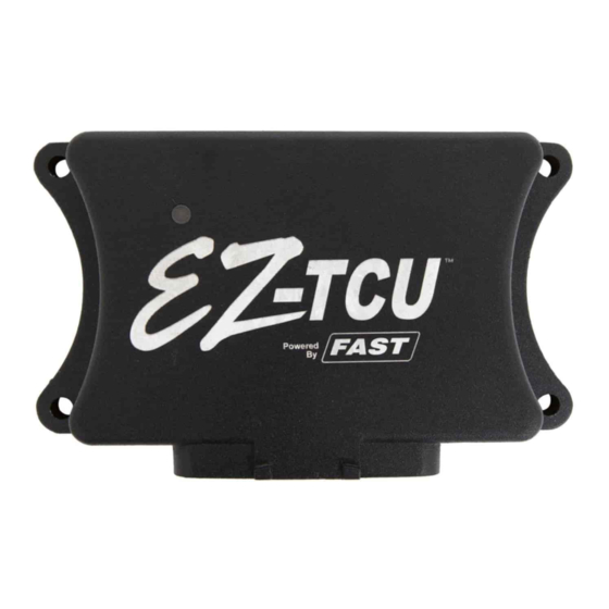
TCU
TCU Installation Notes:
• The TCU is water tight when connected to the wiring harness. It can be mounted in the engine
compartment or in the vehicle's interior. It is good practice to mount the TCU with the
connector facing down. This way, there is less chance of moisture getting into the TCU if it
needs to be disconnected in wet conditions.
• The TCU should not be mounted close to other electrically "noisy" components. In particular,
keep good spacing (try for 2 feet minimum) from ignition components (ignition boxes, coils,
distributors, etc.)
• If mounting in the engine compartment, selecting a location towards the rear will make it easier
to route the communications cable to the interior to allow the handheld to be monitored while
driving. Optional, longer communications cables are available if needed.
• There is an LED on the front face of the TCU – the side with the logo. It will flash if the on-
board diagnostics detects a problem (the LED is lit solid when the TCU is powered up and
working normally). To take advantage of this feature, the TCU will need to be mounted so that
the front face of the TCU is visible. The handheld will also indicate if any faults have been
detected.
EZ-TCU™
Transmission Control Unit
INSTALLATION
Advertisement
Table of Contents

Related Manuals for TCi EZ-TCU


Summary of Contents for TCi EZ-TCU
- Page 1 EZ-TCU™ Transmission Control Unit Thank you for choosing TCI® products; we are proud to be your manufacturer of choice. Please read this instruction sheet carefully before beginning installation, and also take a moment to review the included limited warranty information.
- Page 2 This connects to the round connector on the passenger side of a 4L60E transmission. Or on the driver side of a 4L80E or TCI® 6x Six-Speed transmission. NOTE: Pre-1993 4L80E’s will need an updated internal wiring harness. TCI® PN 276610, GM PN 24200161 or equivalent.
- Page 3 (TCU and a fuel injection system, for example) if needed. It splits off from the THROTTLE connector’s signal wire inside the harness. Remote mount TPS kits are available from TCI® to provide a TPS signal for carbureted applications. TACH IN / RPM MODULE The wire with the female terminal goes to the tach output from an ignition box or other RPM signal source.
- Page 4 TCI® offers shifters and accessories that can be used for this purpose. Color Function Notes Bump Down Use momentary switch to ground to request a downshift. Yellow Bump Up Use momentary switch to ground to request an upshift.
- Page 5 “Tach” outputs that are a perfect RPM signal source for the TCU. If using a clean, processed Tach signal, the TACH IN / RPM MODULE wire in the EZ-TCU™ wiring harness is connected directly to that source - the “Tach” output from an ignition box, etc.
- Page 6 But the TCU will be damaged and system performance will degrade. • Do NOT connect anything from the EZ-TCU™ system to the coil – RPM Module or TACH IN / RPM MODULE wire – when using an aftermarket ignition box.
- Page 7 EZ-TCU™ handles the rest. It sends a calibrated speed signal to the SCU. Installation Sequence This is a general outline of the installation process. Read all of the component specific installation notes for more detail before beginning the installation.
- Page 8 Its first task is to take you through the Setup Wizard. It also serves as a scan tool by displaying live data and diagnostics information. Beyond basic setup, you can also adjust other settings to suit your preferences. Handheld Notes: •...
- Page 9 In addition to live data readings, the Live Data screens also feature several Status Indicators. They show when certain conditions are met. In this picture, the TC indicator is “off”. The PM and MM indicators are “on”. These indicators can serve as a troubleshooting tool by offering a way to verify that the various switched inputs are wired and functioning properly.
- Page 10 • DASH 2 TOT(F) Transmission Oil Temperature. BAT(V) Battery voltage. TPS% Throttle Position Sensor. It’s range is from 0 (resting idle position) to 100 (full open position). The Setup Wizard takes care of calibrating this sensor. It can easily be verified using this display. If you ever notice the TPS reading is not 0 at idle, it should be re-calibrated by selecting TPS CALIBRATE in the Advanced Options section of the handheld.
- Page 11 Setup Wizard The EZ-TCU™ Setup Wizard will walk you through the initial TCU setup. Once you select SETUP WIZARD from the main menu, you will be asked... • START A NEW TUNE? YES will let you continue the Setup Wizard. It will also reset most settings in the Advanced Options menu.
- Page 12 • ADJUST SPEEDO. This setting can be used to fine tune the TCU’s speed reading. It compensates for errors in the entered tire size and rear axle gear ratio. (NOTE: If an external speedometer – as opposed to the MPH display on the EZ-TCU™ handheld - is grossly mis-calibrated, refer to the SPEEDO PPM setting.) While the vehicle is being driven, the screen will display the TCU’s current speed...
- Page 13 Since the point of this adjustment is to verify the speed as reported by the TCU, you will need an independent speed reference for comparison. For example, you could… - pace yourself against another car being driven at a known speed - use a GPS unit that displays ground speed - drive the car on a chassis dyno •...
- Page 14 • 6X OVERLAP. This setting is only used with a TCI® 6x Six-Speed transmission. It affects shift characteristics when shifting between certain gears. Consult with TCI®...
- Page 15 • DONE. This will take you back to the main menu. Error Codes The EZ-TCU™ system features a diagnostics feature. The TCU constantly monitors various inputs for any deviations from normal operation. If any is detected, the LED on the front face of the TCU flashes rapidly as a warning that there is a problem (the LED is lit solid when the TCU is powered on and working normally or it will flash a slower on/off pattern if the TCU started up in Flash Mode).
- Page 16 By enabling Manual Shifting, the transmission can be controlled with two buttons – one for upshift, one for downshift. The buttons can be mounted where ever they are convenient in the vehicle – on the steering wheel, on the shift lever, etc. TCI® offers shifters and accessories that can be used for this purpose.
- Page 17 - Vehicle speed above 10 mph TCI® 6x Six-Speed in Drive Just like the 4L60E and 4L80E transmissions, when the TCI® 6x Six-Speed transmission is operated with the shift lever in the L3/Drive position, it uses 3 forward gears. L2 Shift Lever Position In normal operation, the TCU controls shifting and the transmission will upshift through the gears at the appropriate speeds up to the shift lever position.
- Page 18 TRANSMISSION INFORMATION Transmission Troubleshooting The EZ-TCU™ system relies on properly functioning components within the transmission to do its job correctly. Some of those components can be checked by measuring resistance between the appropriate terminals in the TCU’s main connector. To perform the testing, disconnect the main connector from the TCU and probe the pairs of terminals with a multi-meter set to measure resistance.
- Page 19 * Fit-all refers to a bellhousing configured to accept either a Chevy or BOP engine. (BOP = Buick, Olds, Pontiac, Cadillac) Both the 4L60E/4L65E and 4L80E/4L85E have Chevy bellhousing bolt patterns. TCI® has a full line of adapters to allow these transmissions to be bolted up to Buick, Olds, Pontiac engines as well as popular engines from Ford and Chrysler as well.
- Page 20 Starter Clearance The bellhousing may require modifications if you intend to use a stock starter. As an alternative to modifying the bellhousing, you may choose to install a TCI® starter. Shift Lever Many 1996-later, two-piece case transmissions (primarily trucks) have a shift lever that is about 1”...
Need help?
Do you have a question about the EZ-TCU and is the answer not in the manual?
Questions and answers
what does a battery error mean
TCU PİNOUT
TCU PİNOUT FOR ALL CARS AND TRUCK PDF OR SOFTWARE