Table of Contents
Advertisement
INSTRUCTION MANUAL
WARRANTY
Flyzone guarantees this kit to be free from defects in both
material and workmanship at the date of purchase. This
warranty does not cover any component parts damaged by use
or modification. In no case shall Flyzone's liability exceed the
original cost of the purchased kit. Further, Flyzone reserves the
right to change or modify this warranty without notice.
In that Flyzone has no control over the final assembly or material
used for final assembly, no liability shall be assumed nor
accepted for any damage resulting from the use by the user of
the final user-assembled product. By the act of using the
user-assembled product, the user accepts all resulting liability.
If the buyer is not prepared to accept the liability associated with
the use of this product, the buyer is advised to return this kit
READ THROUGH THIS MANUAL BEFORE STARTING CONSTRUCTION. IT CONTAINS IMPORTANT
INSTRUCTIONS AND WARNINGS CONCERNING THE ASSEMBLY AND USE OF THIS MODEL.
© 2016 Hobbico
®
, Inc. All rights reserved.
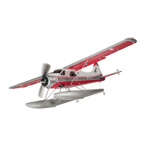
Island Wings Select
SPECIFICATIONS
59.5 in
Wingspan:
[1510mm]
Wing
430 in
Area:
[27.7 dm
3– 3.25 lb
™
Weight:
[1360–1470 g]
Wing
16–17 oz/ft
Loading:
[49– 52 g/dm
immediately in new and unused condition to the place of
purchase.
To make a warranty claim send the defective part or item to
Hobby Services at the address below:
Include a letter stating your name, return shipping address, as
much contact information as possible (daytime telephone
number, fax number, e-mail address), a detailed description of
the problem and a photocopy of the purchase receipt. Upon
receipt of the package the problem will be evaluated as quickly
as possible.
38.5 in
Length:
[980mm]
2
5-channel
Radio:
2
]
radio system
40mm dia.
Motor:
850kV outrunner,
2
40A ESC,
2
]
12x6 propeller
Hobby Services
3002 N. Apollo Dr. Suite 1
Champaign IL 61822 USA
FLZA4120
Advertisement
Table of Contents

Related Manuals for Flyzone DHC-2 BEAVER


Summary of Contents for Flyzone DHC-2 BEAVER
- Page 1 Hobby Services 3002 N. Apollo Dr. Suite 1 In that Flyzone has no control over the final assembly or material Champaign IL 61822 USA used for final assembly, no liability shall be assumed nor...
-
Page 2: Table Of Contents
Havilland DHC-2 Beaver RTF/Tx-R/Rx-R. For anybody who enjoys fl ying fl oat planes or who aspires to do so for the fi rst time, the Flyzone Beaver is the perfect choice because it maneuvers and fl ies off the water so well—you In the United States, please visit: virtually can’t mess up a takeoff or landing unless you try! -
Page 3: Required For Completion
ORDERING REPLACEMENT PARTS LiPo Battery Replacement parts for the Flyzone de Havilland Beaver The RTF edition of the Beaver includes a Flyzone 3S (11.1V) RTF/Tx-R/Rx-R are available using the order numbers in the Replacement Parts List that follows. The fastest, most... -
Page 4: Contents
To locate a hobby dealer, visit the Flyzone web site at www. Mail parts orders Hobby Services fl yzoneplanes.com. Click on the Storefront icon at the top and payments by 3002 N Apollo Drive, Suite 1 of the page to load the Flyzone Dealer Locator. Follow the... -
Page 5: Assembly
ASSEMBLY Mount the Floats NOTE: This instruction manual applies to all versions of the DHC-2 Beaver (Rx-R, Tx-R, and RTF), simply skip the steps that do not apply. Mount the Landing Gear 1. Use a #2 Phillips screwdriver to fasten both main landing gears to the fuselage with three M3x16 screws in each side. -
Page 6: Mount The Horizontal And Vertical Stabilizer
4. Connect a small rubber band to the inside side of each fl oat and water rudder as shown. 2. Use eight M2.5x8 screws to fasten the braces to the 5. Fasten the wire hooks on the end of each rudder fl oats, matching the labels printed or molded into the end line to the connectors in the steering arm. - Page 7 2. Connect the elevator pushrod to the bottom hole in the elevator horn as shown. 4. Key the rudder torque rod down into the receptacle while fi tting the vertical stabilizer (fi n) into the fuselage. Tightly press the assembly down into position. 3.
-
Page 8: Mount The Wings
5. Secure the stab and fi n with the M3x22 screw. Mount the Wings 2. Guide the wires from the right wing into the fuselage, 1. Fasten the wing clips to both sides of the fuselage then slide the wing joiner tube and the fl ap pushrod wire with four M3x10 screws. -
Page 9: Install The Battery
Install the Battery 3. Mount the left wing the same way. 1. Cut two 1” [25mm] strips from the rougher, “hook” side of the included adhesive-back hook-and-loop material. Apply the strips inside the fuselage where shown and press them down tightly so they adhere. 4. -
Page 10: Failsafe Setting
6. Press the LINK button Failsafe Setting & Function (RTF/Tx-R Only) on the TR624 receiver (Tx-R, RTF versions) IMPORTANT: Before installing the propeller, it’s and hold for 2 seconds. important for safety reasons to ensure that the The red LINK light failsafe on the receiver is at the 0% throttle preset should blink and then position as indicated in the instructions below. -
Page 11: Throttle Calibration
If the chime sounds followed by continuous, slow beeps C. To change the brake setting (on or off) reconnect (“beep…beep…beep…beep…”), then the receiver is not the battery to the ESC with the transmitter on and receiving a signal from the transmitter. You may need to the throttle stick all the way up. -
Page 12: Hook Up The Rudder And Elevator
followed by a longer, single, lower tone beep (“BEEEP”) followed by a shorter, higher tone beep (“beep”). If the chimes and beeps do not sound in this manner refer to “FAILSAFE/MOTOR/ESC OPERATION” on page 10 to setup the transmitter and ESC correctly. 5. - Page 13 3. Move the dial or switch on your transmitter that controls the fl aps to the “up” position, rotating the fl ap 1. Connect the wing lighting wires and the aileron servo servo arm clockwise. Remove the screw in the fl ap servo wires to the lighting aileron and fl ap wiring harnesses arm, wet the threads with threadlocker, and then reinstall coming from the receiver.
-
Page 14: Final Flight Preparation
FINAL FLIGHT PREPARATION Check the Control Throws Because the servos and pushrods are factory-installed the control throws should already be correct, but because of the effect the control throws can have on a model, it’s always a good idea to check them anyway. 4-CHANNEL RADIO SETUP (Standard Mode 2) RUDDER... -
Page 15: Mount The Propeller And Spinner
More Control Throw Less Control Throw Mount the Propeller and Spinner Pushrod Pushrod Farther Out Farther In 4. If any of the control throws require adjustment use the programming in your transmitter to increase or decrease the throws accordingly. If the programming isn’t enough or if your radio doesn’t have adjustable throws, the pushrod connectors on the servo arms can be relocated in different holes inward or outward to increase or decrease the throw—... -
Page 16: Motor Safety Precautions
English Metric 2-1/2" 64 mm 2" 51mm 4. Lift the model by your fi ngers between the lines indicating the balance range. As long as the Beaver sits level with your fi ngers on the forward or aft lines or anywhere between the lines it is properly balanced and ready to fl y. -
Page 17: Repairs
the water well. If the winds are really high the Beaver can REPAIRS still be fl own from water, but avoid turning it directly across the wind. Otherwise, the wind can get under the wing and Parts damaged beyond repair can be purchased separately. fl ip the Beaver over. - Page 20 Follow these steps in powering your model: Throttle stick in the minimum position! ALWAYS turn the transmistter “ON” BEFORE plugging in the battery into the plane. When finished flying: ALWAYS unplug the battery from the plane BEFORE turning the transmitter “OFF”.
Need help?
Do you have a question about the DHC-2 BEAVER and is the answer not in the manual?
Questions and answers