ROBOTIQ Wrist Camera Instruction Manual
Vision system for cb-series
universal robots
Hide thumbs
Also See for Wrist Camera:
- Original notice (133 pages) ,
- Instruction manual (134 pages) ,
- Quick start manual (2 pages)

Related Manuals for ROBOTIQ Wrist Camera


Summary of Contents for ROBOTIQ Wrist Camera
- Page 1 Wrist Camera Vision System for CB-Series Universal Robots Instruction Manual Get the latest version of the manual at support.robotiq.com Original Notice...
-
Page 2: Table Of Contents
3.1.1. Wrist Camera Kit for Universal Robots: 3.2. Required Tools and Equipment 3.3. Environmental and Operating Conditions 3.4. Mechanical Installation 3.4.1. Combo of 2-Finger Adaptive Gripper and Wrist Camera for Universal Robots 3.5. Electrical Setup 3.5.1. Power Supply 3.5.2. Cable Management 3.6. - Page 3 6.4. Camera Locate node at a variable Snapshot position 7. Specifications 7.1. Mechanical Specifications of Wrist Camera 7.1.1. Center of Mass and Moment of Inertia 7.2. Electrical rating & performance of Wrist Camera 7.3. Vision System Specifications 8. Maintenance 9. Spare Parts, Kits and Accessories 10.
- Page 4 Wrist Camera Instruction Manual Revisions Robotiq may modify this product without notice, when necessary, due to product improvements, modifications or changes in specifications. If such modification is made, the manual will also be revised, see revision information. See the latest version of this manual online at: support.robotiq.com.
-
Page 5: General Presentation
1. General Presentation The terms "Camera" and "Wrist Camera" used in the following manual all refer to the Robotiq Wrist Camera, while the term "Vision" and "Vision System" used in the following manual all refer to the Robotiq Wrist Camera Vision System for Universal Robots. - Page 6 Fig. 1-1: Schematic representation of the Robotiq Wrist Camera Vision System hardware. Robotiq Wrist Camera: Described in details in sub-section Wrist Camera below. End effector: Any tool mounted on the robot for its application, the Wrist Camera is meant for direct integration of the Robotiq 2-Finger Adaptive Gripper.
- Page 7 Snapshot Position. Fig. 1-2: Schematic representation of the Robotiq Vision System Snapshot Position and workspace concepts. Snapshot Position: the robot pose use to take snapshots from the Wrist Camera. Workspace: the area of interest for the Vision System, it is defined by the Camera's field of view.
- Page 8 Wrist Camera Instruction Manual Object Location: The System will use the Camera Locate node described in the Programming with the Camera Locate Node section locate the object. The figure below represents the object location process. Please refer to the Programming with the Camera Locate Node section for details on the object location process.
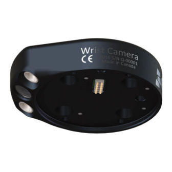
- Page 9 Wrist Camera Instruction Manual Wrist Camera: The hardware at the center of the Vision System is the Robotiq Wrist Camera illustrated in the figure below. Steps on how to install the Wrist Camera are explained in the Installation section. Fig. 1-4: Main features of the Wrist Camera.
-
Page 10: Safety
The operator must have read and understood all of the instructions in the following manual before handling the Robotiq Wrist Camera Vision System for Universal Robots. The term "operator" refers to anyone responsible for any of the following operations on the Wrist Camera Vision System:... - Page 11 Wrist Camera Instruction Manual The Camera needs to be properly secured before operating the robot. Do not install or operate a Camera that is damaged or lacking parts. Never supply the Camera with an alternative current. Make sure all cord sets are always secured at both ends, at the Camera and at the robot.
-
Page 12: Intended Use
The unit may be used only within the range of its technical specifications. Any other use of the product is deemed improper and unintended use. Robotiq will not be liable for any damages resulting from any improper or unintended use. -
Page 13: Installation
Wrist Camera Instruction Manual 3. Installation The following subsections will guide you through the installation and general setup of your Robotiq Wrist Camera Vision System: Section 3.1 details the scope of delivery for the Wrist Camera kit for UR, verify your package. -
Page 14: Scope Of Delivery
Colored background for object teaching ACC-TEACH-BACK; Hardware kit for fixing Wrist Camera on Universal Robots. Caution The hardware for fixing a tool on the Wrist Camera is not provided. Combo of 2-Finger Adaptive Gripper and Wrist Camera for Universal Robots: CUR-AGC-085-RWC or CUR-AGC-140-RWC... -
Page 15: Required Tools And Equipment
The Camera needs to be supplied by a DC voltage source. This power supply is not included with the Camera kit for UR. Required power supply must match the Robotiq device. The following table shows the specifications with regards to the power supply required to operate the Camera and the optional Robotiq Gripper. - Page 16 Warning If your power supply exceeds the specified regulation, over-voltage protection is required. Robotiq recommends the use of the following power supplies: For the 1A output current: TDK-Lambda DPP Series, 100W Single Output DIN Rail Mount Power Supply: DPP30- ©Robotiq inc. 2016-2018...
-
Page 17: Environmental And Operating Conditions
Wrist Camera Instruction Manual 3.3. Environmental and Operating Conditions The Wrist Camera is designed for industrial applications. Always respect the following specified operating environmental conditions: CONDITION VALUE Minimum storage/transit -30°C [-22°F] temperature Maximum storage/transit 70°C [158°F] temperature Minimum operating temperature 0°C [32°F] Maximum operating temperature 50°C [122°F]... -
Page 18: Mechanical Installation
3.4. Mechanical Installation Wrist Camera kit for Universal Robots For mechanical installation of a Wrist Camera on a UR robot along with an end-effector (other than Robotiq's 2- Finger Gripper), follow these instructions and refer to the figure below: Place the Wrist Camera (RWC-CAM-001) on the robot arm. Align the camera's indexing (dowel) pin properly in Universal Robots' bolt pattern. - Page 19 Wrist Camera Instruction Manual Hardware M6 screws to mount an end-effector on the Wrist Camera are not provided. Use M6 screws of appropriate length to secure the end-effector on the robot arm. ©Robotiq inc. 2016-2018...
-
Page 20: Combo Of 2-Finger Adaptive Gripper And Wrist Camera For Universal Robots
Wrist Camera Instruction Manual 3.4.1. Combo of 2-Finger Adaptive Gripper and Wrist Camera for Universal Robots For mechanical installation of a Wrist Camera on a UR robot along with Robotiq's 2-Finger Gripper, follow these instructions, and refer to the figure below: Place the Wrist Camera (RWC-CAM-001) on the robot arm. -
Page 21: Electrical Setup
Power and communication are established with the Wrist Camera via the high-flex device cable. The cable provides a 24V power supply to the Wrist Camera and enables USB 2.0 communication with the Universal Robots controller. Follow these steps to correctly wire the Wrist Camera (or the camera and 2-Finger Gripper combo) to a Universal Robots controller : With the controller turned off, connect the red (24V) and black (0V) wires of the device cable as shown in the figure below. - Page 22 Wrist Camera Instruction Manual Wrist Camera grounding is optional and is done via the robot ground. The camera's indexing pin (dowel) is the ground connector. ©Robotiq inc. 2016-2018...
-
Page 23: Cable Management
Gripper along all axes without pulling out the connectors. Always protect the controller side of the cable connection with a strain relief cable clamp. 3.6. Software Make sure the Wrist Camera is properly mounted on the robot arm and that all electrical wiring is correctly done (refer to the Mechanical Installation section... -
Page 24: Wrist Camera Urcap Installation
Wrist Camera Instruction Manual 3.6.1. Wrist Camera URCap Installation Make sure the Wrist Camera is properly mounted to the robot arm and that all electrical wiring is correctly done (refer to the Mechanical Installation section and the Electrical Setup section). Make sure your Universal Robots software is up to date. - Page 25 Wrist Camera Instruction Manual PolyScope 3.6 From PolyScope's home page, tap Setup Robot and go to URCaps Setup. Tap the plus ( + ) sign and open Robotiq_Wrist_Camera-X.X.X.urcap from the USB stick. Tap Restart and wait for PolyScope to reopen.
- Page 26 Wrist Camera Instruction Manual Fig. 3-8: Camera dashboard with camera firmware upgrade. Wait for the vision system to start. The installation is completed. In order to use another USB drive on the controller, reboot the robot controller. Do not unplug the 16 Gb USB stick or the USB license dongle, even after the installation has been completed.
- Page 27 3. Go to the Camera tab. The output image will appear. Center of Mass Prior to use over Universal Robots, adjust the center of mass and payload from the Installation tab (refer to Mechanical Specifications of Wrist Camera section). ©Robotiq inc. 2016-2018...
-
Page 28: Update And Uninstall
Wrist Camera Instruction Manual 3.6.2. Update and Uninstall Warning Updating the Wrist Camera software, unplugging the USB storage device and/or switching USB ports must always be done while the robot is initialized and running. 3.6.2.1. Version 1.1 and following PolyScope 3.6 1. From a robot program, go to the Installation tab. - Page 29 Wrist Camera Instruction Manual ©Robotiq inc. 2016-2018...
-
Page 30: Version 1.0.2 And Previous
Wrist Camera Instruction Manual 3.6.2.2. Version 1.0.2 and previous 1. On a blank USB stick, add the following file : urmagic_uninstall.sh . 2. From a Robot Program, go to the Installation tab. Choose Camera and go to the Camera tab. -
Page 31: Snapshot Position
Wrist Camera Instruction Manual 4. Snapshot Position Prior to teaching object with the Camera Locate URCaps node (refer to the Programming with the Camera Locate Node section), the operator must define a Snapshot Position using the Snapshot Position wizard. The following section and sub- sections will guide you through this process. - Page 32 Wrist Camera Instruction Manual Along with your kit you will have the calibration board used for UR3 robots on one side the the board, part number ACC-CALIB-BOARD. The color balance circles are not used yet with the vision system and are for future use. If you loose or...
-
Page 33: Guidelines On Snapshot Position
Angle of the camera: Snapshot position should consider the Camera angle: Robotiq greatly recommends to have the Camera perpendicular to the surface: Be as close as possible to perpendicular, avoid reflections. Object should be seen from the top view, not from the side. -
Page 34: Snapshot Position Wizard
In the drop-down list, select the Feature you wish to use. Tap Define to launch the wizard. Wizard step 1: Define Snapshot Position Move the robot arm using the Freedrive to place the Wrist Camera. Remember the guidelines from the Guidelines on Snapshot Position section: Distance will determine field of view and size of objects to be located. - Page 35 Wrist Camera Instruction Manual Make sure the Camera see the whole board Snapshot Position will determine the field of view, notice that the calibration step position does not have to be the same as Snapshot position. Thus, you can have a small field of view, then move back for calibration step.
- Page 36 Wrist Camera Instruction Manual If the accuracy is larger than +/- 4mm, an message will inform you that you should perform the calibration again. When you tap Accept, you will exit the wizard and the process is completed. Once the calibration has been accepted, the Snapshot Position will appear in the Snapshot Positions tab with the name of the Feature Point previously created.
- Page 37 Wrist Camera Instruction Manual Features Icon Feature Description Define Launches the Snapshot Position definition wizard. Show grid Displays a grid on the camera's field of view. Meant to test the camera’s height relative to the workplane : a part should be at least as large as a square of the grid.
-
Page 38: Copy A Calibration
Wrist Camera Instruction Manual 4.3. Copy a Calibration When defining a snapshot position, it is possible to copy the calibration from another snapshot position. This allows for a faster snapshot position modification when using the same work plane. Work Plane To ensure proper precision, the work plane surface of both (new and copied) snapshot positions should be the same. -
Page 39: Object Teaching
Wrist Camera Instruction Manual 5. Object Teaching Once the snapshot position is defined (see section 4), the operator can use the Camera Locate node within a Universal Robot program to teach an object to locate. The following section and sub-sections will guide you through this process. -
Page 40: Guidelines On Object Teaching
Wrist Camera Instruction Manual 5.1. Guidelines on Object Teaching Info During the object teaching, the ambient light must be approximately 500 lux, and stable. At runtime, this condition is not required. The following must be considered when going through the object teaching process : Objects criteria for reliable localization: Object is quasi-flat, respecting a maximum ratio of 1:1 between its height and its smallest dimension;... - Page 41 This will decrease the cycle time. The ambient light should be diffuse. Avoid high light intensity spots on your background. This will result in a faster object detection by the Wrist Camera and a lesser risk of false detection. ©Robotiq inc. 2016-2018...
-
Page 42: Teach Object Wizard
Wrist Camera Instruction Manual 5.2. Teach Object Wizard Camera Locate Node To insert a Camera Locate node in the robot program, from the Universal Robots PolyScope interface: Start a new program or open yours, then go to the Program tab. - Page 43 Play button that displays contextual help videos for visual support in going through the teaching steps Question mark button that displays an HTML version of the Wrist Camera's instruction manual directly on the teach pendant (feature to be implemented in the near future) Fig.
-
Page 44: Automatic Method
Wrist Camera Instruction Manual 5.2.1. Automatic Method Caution A Snapshot position must be defined to launch the object teaching wizard. If no Snapshot position has been defined, please refer to the Snapshot Position section. 5.2.1.1. Select Calibration At any moment during the teaching process, the user can access contextual help videos with the Play button. -
Page 45: Select Model
Wrist Camera Instruction Manual 5.2.1.2. Select Model At any moment during the teaching process, the user can access contextual help videos with the Play button. Prior to selecting a model, the user will place a background on the workplane and then position the object on the background. - Page 46 Wrist Camera Instruction Manual Automatic area selection The object is selected since the Magic Wand tool is enabled by default. The Magic Wand feature allows to locate objects on the background without user intervention. Info For the automatic area selection feature to function properly, the user has to employ a uniform background, and a single object with well defined edges.
- Page 47 Wrist Camera Instruction Manual Manual area selection The user then selects an area by tapping the screen and dragging his/her finger to contain the desired object in the selection area. Fig. 5-5: Select Model step with Manual area selection feature The manual area selection is useful for careful inspection of specific features using the zoom function.
- Page 48 Wrist Camera Instruction Manual Camera views Standard view When in standard view mode, the camera feed displays a reasonably faithful image based on what is normally perceived by the human eye (colored object on colored background). Fig. 5-6: Select Model step with standard view enabled Tapping the eye button in the upper right corner of the camera feed window will bring up the machine view.
- Page 49 Wrist Camera Instruction Manual Machine edge view The user can access the machine view by tapping the Color view button in the upper right corner of the camera feed window. The machine view makes no discrimination between colors; it rather highlights the contour of the selected object.
- Page 50 Wrist Camera Instruction Manual Machine color view The user can access the Machine color view by tapping the Machine edge view button in the upper right corner of the camera feed window. The Machine color view displays the elementary colors perceived by the vision system.
- Page 51 Wrist Camera Instruction Manual Camera settings In order to access the advanced camera settings, tap the camera/gear icon in the lower left corner of the camera feed. Camera settings Camera LEDs are ON; please refer to the Camera LEDs section for more details.
- Page 52 Wrist Camera Instruction Manual Camera LEDs Camera LEDs ON Camera LEDs OFF The LEDs, when turned ON, sometimes highlight undesirable features or create reflections that distort the teaching process. It is recommended to try both settings when teaching the object in order to select the most conclusive result.
- Page 53 Wrist Camera Instruction Manual Focus Info Focus features can be used to sharpen or diminish the contrast between the object and the background, and adjust the depth of field. The settings will be captured at runtime except if changes are made to the model during the Configure Model step.
- Page 54 Wrist Camera Instruction Manual The manual focus feature allows the user to adjust the depth of field. Tapping the flower button reduces the focus value, making the depth of field narrower, while tapping the mountain button increases the focus value, making the depth of field deeper.
- Page 55 Wrist Camera Instruction Manual Zoom out Fig. 5-12: Select Model step with Zoom out button highlighted In order to zoom out from the selection area, the user has to tap the magnifier with a minus symbol in the lower right corner of the teach pendant interface.
-
Page 56: Edit Model
Wrist Camera Instruction Manual 5.2.1.3. Edit Model At any moment during the teaching process, the user can access contextual help videos with the Play button. Right after accepting the model at the end of the Select Model step, the camera automatically zooms in on the object selected. - Page 57 Wrist Camera Instruction Manual Quick selection modes Tap the arrow to the left of the quick selection tool to expand the selection modes menu. Fig. 5-14: Edit Model step with quick selection modes expanded Outline only The Outline only selection tool is used to highlight the contour of the object Info The selection area bleeds off the edge of the object to capture the background color.
- Page 58 Wrist Camera Instruction Manual Caution The Outline & surface selection tool is not available for an object that has been selected manually at the Select Model step. This prevents users from selecting the partial outline and/or surface of an object, which could lead to faulty contrasts and edge detection.
- Page 59 Wrist Camera Instruction Manual Tools Tap the arrow to the left of the tools button to expand the tools menu. Marker The marker tool can be used to highlight features and edges to include and keep in the selection area.
- Page 60 Wrist Camera Instruction Manual Caution Tapping the Accept model button (check mark) takes a picture of the model that will act as the first step in the next phase of the teaching process: Refine Model. ©Robotiq inc. 2016-2018...
-
Page 61: Refine Model
Wrist Camera Instruction Manual 5.2.1.4. Refine Model The Refine Model step prompts the user to take photos of the model in four different orientations. The purpose of this step is to remove shade effects associated with the edges of the object in order to refine the model. -
Page 62: Validate Model
Wrist Camera Instruction Manual 5.2.1.5. Validate Model At any moment during the teaching process, the user can access contextual help videos with the Play button. The Validate Model step will start right after the fourth picture is taken at the end of the Refine Model step. -
Page 63: Scan Model
Wrist Camera Instruction Manual 5.2.1.6. Scan Model At any moment during the teaching process, the user can access contextual help videos with the Play button. Warning Scanning is an automatic process; the robot will move in order to perform calibration. Make sure the robot's work space is clear. -
Page 64: Parametric Method
Wrist Camera Instruction Manual 5.2.2. Parametric Method When teaching a simple geometry object, it is recommended to use the Parametric method. It builds a model based on parameters of a basic 2D shape (circle, ring, square or rectangle). This method allows the vision system to recognize and locate with high robustness objects that have few distinctive features such as raw material blanks. -
Page 65: Circle
Wrist Camera Instruction Manual 5.2.2.1. Circle At any moment during the teaching process, the user can access contextual help videos with the Play button. Enter the circle diameter (D) and the height (h) at which the circle is located. Tap the Define button. -
Page 66: Ring
Wrist Camera Instruction Manual 5.2.2.2. Ring Enter the ring outer diameter (D), inner diameter (d) and the height (h) at which the ring is located. Tap the Define button. Fig. 5-17: Definition of a ring 2D shape. 5.2.2.3. Rectangle Enter the rectangle length (l), width (w) and the height (h) at which the rectangle is located. Tap the Define button. -
Page 67: Square
Wrist Camera Instruction Manual 5.2.2.4. Square Enter the square length (l) and the height (h) at which the square is located. Fig. 5-19: Definition of a square 2D shape. When the process is done, the wizard will switch to the Configure Model step. Please refer to the Configure Model section for more details. -
Page 68: Configure Model
5.2.3. Configure Model Test locating object button; the Vision System will search for the object in the field of view of the Wrist Camera. Back button; after testing an object's location, tap to return to the output image of the camera. - Page 69 Wrist Camera Instruction Manual Camera settings button; please refer to the Camera settings section for more details. Score value box; display section in which the detection score appears after testing the object location. Object location button; when an object is found, tap this button to view its position relative to the robot base.
-
Page 70: Multiple Objects Detection
Wrist Camera Instruction Manual 5.2.3.1. Multiple objects detection In order to enable the multiple objects detection, tap the multi-object button from the Configure Model step. Fig. 5-20: Configure Model with multi-object button highlighted. Once in the multi-object menu, tap the plus (+) symbol to increase the maximum number of objects to detect, or tap the minus (-) symbol to reduce that number. -
Page 71: Color Validation
Wrist Camera Instruction Manual 5.2.3.2. Color Validation Color validation adds reliability to the camera locate feature. Whereas editing the model allows to select, configure and save the shape, outline and area of the model, the color validation allows the system to save the color signature of objects or features. - Page 72 Wrist Camera Instruction Manual Turn on color validation by tapping the red button on the right side of the screen. Fig. 5-23: Configure Model Color model with ON/OFF button highlighted Color sampling tools Marker The marker tool can be used to highlight features and edges to include and keep in the color sampling area.
- Page 73 Wrist Camera Instruction Manual Eraser The eraser tool can be used to ignore features and edges in the color sampling area. Slide your finger or pointing device on the undesired area(s) on the teach pendant. Rectangle+ (add area) The rectangle+ (add area) tool can be used to quickly highlight desired areas for color sampling.
- Page 74 Wrist Camera Instruction Manual Parametric method Tap the color validation button to access the color validation menu. Fig. 5-24: Configure Model Step (Parametric method) with color validation button highlighted. ©Robotiq inc. 2016-2018...
- Page 75 Wrist Camera Instruction Manual Turn on color validation by the tapping the red button on the right side of the screen. Fig. 5-25: Edit Color Validation menu (Parametric method) with ON/OFF toggle button highlighted. Color sampling tool In the parametric method, given the inherent symmetry of the objects located by the system, color validation is supported via an expendable/shrinkable color selection zone, on par with the contour of the object to be located.
-
Page 76: Detection Thresholds And Scores
Wrist Camera Instruction Manual 5.2.3.3. Detection thresholds and scores At the Configure model step, the user can tap the Detection threshold button in the lower right corner to expand the detection threshold settings. Fig. 5-26: Configure Model Step with detection thresholds highlighted. - Page 77 Wrist Camera Instruction Manual Info In the context of multiple objects detection, each object detected has its own set of detection score values (%). ©Robotiq inc. 2016-2018...
- Page 78 Wrist Camera Instruction Manual Edges detection threshold and score If the object is found, you will see the object outlined, surrounded by a blue rectangle, with the detection score value (%). Other objects detected will be surrounded by a white rectangle. Tap the other object(s) to display their own set of detection score values.
- Page 79 Wrist Camera Instruction Manual To avoid false detections, remove the object from the workplane, decrease the detection threshold to 0% and try to locate the object. If a false detection occurs on your workplane, you will see an object detected with the detection score.
- Page 80 Wrist Camera Instruction Manual Color detection threshold and score Color detection can only happen following a successful edge detection. Caution Color validation must be enabled in order to go through the color detection step. Please refer to the Color Validation section for more details on enabling color validation.
-
Page 81: Camera Settings
Wrist Camera Instruction Manual 5.2.3.4. Camera settings Warning Camera settings can be adjusted at the Select Model step of the Automatic teaching method and/or at the Configure Model step of the Teach object wizard. Editing the camera settings at the Configure Model step will override the settings selected at the Select Model step of the Automatic teaching method. -
Page 82: Programming With The Camera Locate Node
Wrist Camera Instruction Manual 6. Programming with the Camera Locate Node Fast Cycle Time If the ambient lighting is stable during run-time, you can enable the fast cycle time configuration. To do so, go to the Installation tab from the program. Choose Camera and go to Configurations. - Page 83 Wrist Camera Instruction Manual By enabling the fast cycle time configuration, the camera exposure will be set the first time the program enters a Camera Locate node – at runtime. For all other Camera Locate nodes, the camera will keep the exposure settings from the first run.
- Page 84 Wrist Camera Instruction Manual Programming The first thing to do after completing the object teaching is to add a Move node to the Snapshot position. When you exit the object teaching wizard, the robot arm is already in the Snapshot position location. You can simply add a MoveJ command before the Camera Locate node and set it to the location the robot arm is at (see Snapshot_pos_1 from the next figure).
-
Page 85: Linear Move With Feature - Pick And Place Template
Wrist Camera Instruction Manual 6.1. Linear Move with Feature – Pick and Place Template Info The URCaps installation will provide you with a template program, template_vision.urp, that can be found in the program folder. The figure below shows this template. This section guides you through the process of doing a similar program. -
Page 86: Object_Location Pose
Wrist Camera Instruction Manual Fig. 6-3: Template program for a Camera Locate pick & place application. 6.2. object_location pose Once a snapshot position is defined, the workplane used for the calibration gets its own coordinate system, regardless of its orientation. This coordinate system is shown in the figure below. - Page 87 Wrist Camera Instruction Manual Fig. 6-5: object_location pose on the workplane used for the calibration. object_location is a variable with the pose structure (x, y, z, x rotation, y rotation, z rotation): x: x position of the object detected, relative to the robot's base reference frame.
- Page 88 Wrist Camera Instruction Manual Program Example The program examples below show how to use the object_location pose variable.The first one simply moves the robot so that the TCP goes directly on the detected object. Make sure the TCP is set properly to avoid collisions.
-
Page 89: Edit Detection Threshold And Object Location
Wrist Camera Instruction Manual 6.3. Edit Detection Threshold and Object Location It is possible to edit both the detection threshold and the object location after the Teach object wizard has been completed. To do so, select the Cam Locate node, go to the Command tab and tap Test/Modify. -
Page 90: Camera Locate Node At A Variable Snapshot Position
Camera Locate node. The pose at which the robot enters the Camera Locate node is calculated knowing how many trays are stacked. The snapshot_position_offset is calculated accordingly in order for the Wrist Camera to consider the pose offset from the original snapshot position. - Page 91 Wrist Camera Instruction Manual precision, as the workplane can be slightly different depending on where the calibration has been performed. Be aware of this when programming a Camera Locate node relative to another one. ©Robotiq inc. 2016-2018...
-
Page 92: Specifications
Caution The following manual uses the metric system, unless specified, all dimensions are in millimeters. The following sub-sections provide data on the various specifications for the Robotiq 2-Finger 85 and 140 Adaptive Grippers. Section 7.1 mechanical specifications of the Wrist Camera: Dimensions;... -
Page 93: Mechanical Specifications Of Wrist Camera
Wrist Camera Instruction Manual 7.1. Mechanical Specifications of Wrist Camera Fig. 7-1: Wrist Camera's dimensions. Specification Value Maximum load 10 kg 40 Nm Weight (without tool plate) 160 g Weight (with tool plate) 230 g Added height (without tool plate, for use with 2- 13.5 mm... -
Page 94: Center Of Mass And Moment Of Inertia
7.1.1. Center of Mass and Moment of Inertia The coordinate system used to calculate the moment of inertia and center of mass of the Wrist Camera is the base of the Camera which correspond to the UR tool flange reference [0,0,0]. - Page 95 Wrist Camera Instruction Manual Fig. 7-2: Center of Mass with and without the toolplate. ©Robotiq inc. 2016-2018...
-
Page 96: Electrical Rating & Performance Of Wrist Camera
Wrist Camera Instruction Manual 7.2. Electrical rating & performance of Wrist Camera Robotiq recommends you supply the Wrist Camera from the Universal Robots controller power supply as shown in the Electrical Setup section; if for any reasons you cannot do so, here are the electrical specifications of the Camera:... -
Page 97: Vision System Specifications
Wrist Camera Instruction Manual 7.3. Vision System Specifications Accuracy The accuracy of the vision system is as described in the table below and depends on the robot model used. It is valid for the area where the calibration board was located during the calibration process. - Page 98 Wrist Camera Instruction Manual Field of view Specification Value UR10 Maximum board distance (cm) 36 x 27 64 x 48 100 x 75 Minimum board distance (cm) 10 x 7.5 10 x 7.5 10 x 7.5 Info Field of view is (FoV) determined by Snapshot position. To get the minimum FoV, the camera must be placed at 7 cm above the work plane.
- Page 99 Wrist Camera Instruction Manual Part dimensions The maximum part size that can be detected by the Wrist Camera is 60% field of view's dimension. The minimum is 10%, no matter the robot or the field of view size. Fig. 7-5: Maximum and minimum part size.
- Page 100 Wrist Camera Instruction Manual Background contrast To ensure a good model and part detection from the Vision system, you should use a background that has a high color contrast with the part to be detected. You must choose colors that are apart horizontally on the HSV cone shown below.
-
Page 101: Maintenance
Wrist Camera maintenance The Camera does not need any maintenance. Make sure that the lens is kept free from liquid or dust at all time. Robotiq recommends you use the provided bag with your camera along with alcohol to clean the lens. -
Page 102: Spare Parts, Kits And Accessories
Item Ordering Number Wrist Camera Kit for Universal Robots. RWC-UR-KIT Includes Wrist Camera, calibration board, tool plate for UR, USB memory stick, license and hub and all hardware. Replacement Wrist Camera. Includes 10 m pigtail cable. RWC-CAM-001 Wrist Camera tool plate for ISO 9409-1-50-4M6 pattern (Universal Robots). -
Page 103: Troubleshooting
Wrist Camera Instruction Manual 10. Troubleshooting Info To view the Vision server, Camera URCap and Camera firmware versions, proceed with the following: From a Robot program, go in the Installation tab. Choose Camera Go in the About tab. The versions will appear. Make sure they are the latest release and that they are all updated simultaneously. -
Page 104: Led Status
Blinking blue and red Major fault: Check the power supply to make sure it is 24 V DC +/- 10%. Camera's input voltage is The Wrist Camera should not operate at a not sufficient temperature higher than 50°C. Temperature is greater than 70°C Solid blue Not fault and communicating. -
Page 105: Warranty And Patent
Robotiq shall not be liable for damages resulting from the use of the Robotiq Wrist Camera or Robotiq Vision System, nor shall Robotiq be responsible for any failure in the performance of other items to which the Wrist Camera is connected or the operation of any system of which the Vision System may be a part. - Page 106 This warranty excludes failure resulting from: improper use or installation, normal wear and tear, accident, abuse, neglect, fire, water, lightning or other acts of nature, causes external to the Wrist Camera, the Vision System or other factors beyond Robotiq's control.
-
Page 107: Contact
Wrist Camera Instruction Manual 12. Contact www.robotiq.com Contact Us Phone 1-888-ROBOTIQ (762-6847) (+1) 418-380-2788 Outside US and Canada 1-418-800-0046 Technical Support and Engineering extension 3 Sales extension 2 Head office Robotiq: 966, chemin Olivier Suite 500 Lévis, Québec G7A 2N1 Canada Where automation Pros come to share their know-how and get answers. -
Page 108: Harmonized Standards, Declarations And Certificates Dd
Wrist Camera Instruction Manual A. Harmonized Standards, Declarations and Certificates A1. Declaration of Incorporation ©Robotiq inc. 2016-2018...
Need help?
Do you have a question about the Wrist Camera and is the answer not in the manual?
Questions and answers