Table of Contents
Advertisement
Advertisement
Table of Contents

Related Manuals for Fisher Scientific accumet AP 110 accumet AP 115 accumet AP 125


Summary of Contents for Fisher Scientific accumet AP 110 accumet AP 115 accumet AP 125
- Page 1 ® AP 110 AP 115 AP 125 INSTRUCTION MANUAL 68X452201 Rev. A 07/08...
-
Page 3: Table Of Contents
Thank you for selecting an accumet portable (AP) meter. This portable meter is a microprocessor-based instrument with many user-friendly features, all of which are accessible through the keypad. Please read this manual thoroughly as well as your separate electrode manual before operating your instrument. TABLE OF CONTENTS 1. -
Page 5: The Instrument
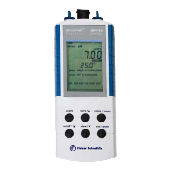
1. THE INSTRUMENT Before operating the meter, please familiarize yourself with the location and function of its various display elements, keypad and connectors. Figure 1 Front view of meter... -
Page 6: Display
1.1 DISPLAY Figure 2 illustrates the liquid crystal display area. Each of the display elements is referenced in the figure and described below. Meter Prompts Buffers Standards Figure 2 Display annunciators SYMBOL DESCRIPTION Battery indicator with scale Meter operating with optional AC power supply Set Up mode Setup View data stored in memory... -
Page 7: Keypad
1.2. KEYPAD Figure 3 illustrates the keypad area. The function of each key is described below. save/▲ mode setup/meas on/off/ view/ ▼ std/enter Figure 3 Meter Keypad DESCRIPTION Press to turn the meter ON. The meter will default to the last measurement mode used. When ON, press this key to turn the backlight ON or on/off/ ☼... -
Page 8: Connectors
1.3 CONNECTORS Figure 4 illustrates the Top View showing connectors of the AP meter. Note that the meter is waterproof only when the blue rubber plugs and/or the appropriate ATC probe are used. If the meter is totally submersed, water may enter the BNC connector. If necessary, dry the connector to avoid corrosion. -
Page 9: Features
2. FEATURES FEATURE DESCRIPTION Operator-selectable using setup/meas key, Display choose 8888.8 for 0.1, 888.88 for 0.01, Resolution 88.888 for 0.001 When enabled, display locks on current value Auto Read when stable indicator appears. Press meas key to unlock and resume reading When enabled, meter automatically turns off Battery after 20 minutes of inactivity... -
Page 10: Ph Operation
1. Condition your electrode by soaking as needed in electrode storage solution, pH 4 or 7 buffer, or KCl solution. Complete hydration can take anywhere from minutes to overnight for very dry electrodes. 2. Twist the metal shorting cap to remove it from the BNC jack of the meter. - Page 11 HOLd ‘Yes’ or ‘No’ by using the save/▲or view/▼keys. Press std/enter to accept. 2. To display the % slope efficiency ‘EFF%’ and mV offset ‘mV’ press setup/meas twice. 3. To erase an existing pH standardization/ calibration press setup/meas until ‘Clear buf std’ (Clear buffer standard) appears on the screen.
-
Page 12: Ph Standardization
5.2 pH Standardization For best results, standardizing (calibrating) your meter/ electrode system against certified accurate solutions is strongly recommended due to electrode variations and changes in electrode response over time. Daily standardization with fresh buffers is common. 1. Press mode until the display indicates the pH mode. -
Page 13: Mv Operation
appearance of the STABLE annunciator). The pH reading may be recorded at this time. a. If AUTO is not displayed, the auto read hold function is not active, and the meter will continuously monitor the live pH value. b. If AUTO is displayed, the meter will lock the measured value on the screen when the STABLE annunciator appears. -
Page 14: Mv Measurement
exhaustion once on, the meter remains on — until the meter is manually turned off. 4. To set meter time and date press setup/meas until ‘MM/DD/YY’ appears. save/▲or view/▼keys to select the appropriate digits. Press std/enter to confirm selection and to move from minutes to hours;... -
Page 15: R.mv Standardization
4. To change the R.mV resolution press setup/meas until ‘88888’ appears. Press std/enter when the desired resolution is displayed below; 8888.8 to select 0.1 8888 to select 1 5. To activate or deactivate the Automatic Shut off function press setup/meas until ‘A.Off’ appears. Select ‘Yes’... -
Page 16: Ion Operation (Ap125 Only)
3. When the meter senses that the displayed value is stable, STABLE will appear under the displayed value. Record the reading at this time. This value is the millivolt reading relative to the applied offset. Note: The AUTO read function is not applicable in the mV and R.mV measurement modes. -
Page 17: Ion Standardization
5. To activate or deactivate the Automatic Shut off function press setup/meas until ‘A.Off’ appears. Select ‘Yes’ or ‘No’ by using the save/▲or view/▼keys and press std/enter to confirm your selection. If ‘Yes’ is selected, the meter automatically turns off after 20 minutes of inactivity. Note: Selecting ‘No’... -
Page 18: Measurement In Ion Mode
4. Immerse the ion selective electrode(s) into the standard solution selected in Step (3) adding ISA as needed. Provide moderate stirring if possible. 5. Allow the mV value to reach a constant reading (little variation over 30 seconds as well as the appearance of the STABLE annunciator). -
Page 19: Measuring Temperature
Note: enabling the AUTO read hold function can lead to erroneous values if the electrode is slow to respond such as testing of viscous or dirty samples, changing temperatures, etc. 9. MEASURING TEMPERATURE AP meters can utilize automatic temperature compensation (ATC) manual temperature... -
Page 20: Temperature Standardization (Mtc)
9.2 Temperature Standardization (MTC) When not utilizing an ATC probe for best results, the default temperature reading can be adjusted from the factory default value of 25 C to ensure optimal accuracy. For example, if your pH buffers and samples are at 20 C and you do not have an ATC probe, it would be desirable to change the MTC from 25... -
Page 21: Data Storage
10. DATA STORAGE 10.1 Storing Value into Memory The AP 110/115/125 meter can store up to 200 data sets in its non-volatile memory. In any Measurement mode, press save/▲to store the measured value. “Lo XX Stored (Location number stored) appears on the screen. The value is now stored in the meter’s non-volatile memory and the meter returns to Measurement mode. -
Page 22: Specifications
SPECIFICATIONS AP 110 AP 115 AP 125 Range -2.00 to -2.00 to 20.00 20.000 Resolution 0.1 / 0.01 0.1 / 0.01 / 0.001 Relative accuracy ± 0.01 ± 0.002 Input Input Impedance ohms No. of calibration 1 to 6 points points (depending on Buffer selection) USA: 2.00, 4.00, 7.00, 10.00, 12.00... - Page 23 Temperature AP 110 AP 115 AP 125 Temp. Range -5 to 100 Temp. Resolution Temp. Accuracy ± 0.3 Features AP 110 AP 115 AP 125 Date & Time Auto-Buffer Recognition Auto Hold Mode Auto Shut Off Selectable after 20 minutes, Default (on) Memory 200 data sets Slope/Offset...
-
Page 24: Error Messages
4,7,10 & Rinse, 20 mL pouches x 5 each 13-300-147 For a complete selection of electrodes and accessories, please refer to the Fisher Scientific Catalog, website, or contact your Fisher Scientific Sales Representative. To place an order, call 1-800/766-7000, fax 1-800/926-1166, or online www.fishersci.com...
Need help?
Do you have a question about the accumet AP 110 accumet AP 115 accumet AP 125 and is the answer not in the manual?
Questions and answers