Table of Contents
Advertisement
Quick Links
Advertisement
Table of Contents

Summary of Contents for Sens DC PowerCab 120
- Page 1 ™ ® SENS DC PowerCab Installation, Operation, & Maintenance Manual...
- Page 2 C&C Power, Inc. Longmont, Co 80501 395 Mission Street www.sens-usa.com Carol Stream, IL 60188 Technical Support: Phone: (303) 678-7500 or (800) 742-2326 Email: service@sens-usa.com SENS, the SENS logo and PowerCab are trademarks of Stored Energy Systems LLC. 8/24/2017 755-00129 R04...
-
Page 3: Table Of Contents
ABLE OF ONTENTS 1. Important Information About This Manual ................. 4 1.1 Manual Symbols ........................4 2. Introduction ..........................5 3. Safety Precautions ........................6 4. Inspection Upon Receipt of Goods ....................8 4.1 General ..........................8 4.2 Visible Damage ........................8 4.3 Concealed Damage ........................ -
Page 4: Important Information About This Manual
™ ® SENS DC PowerCab 1. I MPORTANT NFORMATION BOUT ANUAL SAVE THESE INSTRUCTIONS! This manual contains important information that is needed during the installation and maintenance of the system. 1.1 M ANUAL YMBOLS Warning / Caution: Indicates information provided to protect the user against personal injury, safety hazards and/or possible equipment damage. -
Page 5: Introduction
United States. All SENS products are built to the highest industry standards and are Hi Pot tested to UL standards prior to shipment. All standard configurations are C-UL listed. -
Page 6: Safety Precautions
™ ® SENS DC PowerCab 3. S AFETY RECAUTIONS Before installing or maintaining this system, it is extremely important to read this manual and be sure that all system drawings and schematics are reviewed and clearly understood. If there are any questions concerning this manual or any of the installation or maintenance procedures and/or requirements please contact a C&C... - Page 7 ™ ® SENS DC PowerCab DC Power and Batteries can be very dangerous and have extremely high short circuit current. Electrical shock, severe burns, fire or death can result from a system short. To avoid personal injury including electrical shock, severe burns and possible death, all jewelry including bracelets, rings and watches must be removed prior to installing or servicing this system.
-
Page 8: Inspection Upon Receipt Of Goods
Note any damage to the internal packaging, then request an inspection by the carrier and file a concealed damage claim. If there is a material shortage, contact a representative at SENS to file a claim. -
Page 9: System Overview
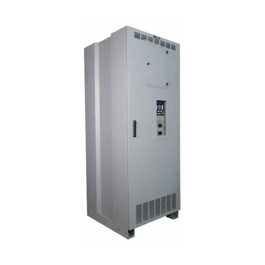
5. S YSTEM VERVIEW The DC PowerCab 120 is a non-stop DC power system designed to deliver uninterruptible DC power to critical loads. PowerCab includes a DC power supply/charger, storage battery string, and DC distribution to load center. In addition to the charger, battery, distribution panel and cabinet, PowerCab can be optionally equipped with: •... -
Page 10: System Specifications
™ ® SENS DC PowerCab 6. S YSTEM PECIFICATIONS 6.1 B ATTERIES Type: Valve Regulated Lead Acid (VRLA), sealed, non-spillable Amp-Hour Options: 100 AH, 150AH, 170AH or 200AH Voltage: 12 VDC Nominal Only cabinets with Flame Retardant Batteries are suitable for computer room use. -
Page 11: Optional Ac Output
When AC power fails, the systems batteries will discharge in order to provide the necessary backup power to the load. If the DC PowerCab 120 is equipped with the Low Voltage Disconnect (LVD) feature, the system load will be automatically disconnected at the customer adjustable LVD disconnect voltage setting. - Page 12 ™ ® SENS DC PowerCab Operating Temperature: 20°C to 25°C (68°F to 77°F) recommended for optimum battery performance. Ventilation: Ventilation holes located in the front, rear, and top of the cabinet. Clearance around the equipment should be as suggested by NEC and/or all applicable national and local codes. The battery cabinet does not require rear access or rear clearance.
-
Page 13: Installation
™ ® SENS DC PowerCab 7. I NSTALLATION 7.1 P REPARATION 7.1.1 E QUIPMENT NSPECTION Remove the equipment from the packaging material and inspect for any shipping damage that may have been overlooked upon receipt of goods. Verify that the system includes all necessary hardware for installation. -
Page 14: Equipment Mounting
Spread forks to maximum possible width under load. Lift cabinet from bottom only. Wear safety shoes.) 1. The SENS DC PowerCab 120 cabinet is equipped with pallet jack and/or forklift access openings in the front and rear of the cabinet. Move the equipment into the desired location and set into place. -
Page 15: System Operation
6. Connect the jumper that was left off during shipment and install as shown on the system schematic. Torque connections properly. 7.2.5 S YSTEM PERATION Please refer to the Charger Operation Installation and Operation Manual included with the SENS DC PowerCab 120 product for startup and operation information for the charger unit. 8/24/2017 755-00129 R04... -
Page 16: System Maintenance
™ ® SENS DC PowerCab 8. S YSTEM AINTENANCE Before proceeding with system maintenance, be sure to review and understand all of the SAFETY PRECAUTIONS in this manual! Verify that the Battery Main breaker on the panelboard and Charger AC Main breaker (on the charger unit) are in the off/open position before servicing the system. - Page 17 ™ ® SENS DC PowerCab 9. Put the new battery into place. Make sure new battery is installed properly regarding polarity orientation. Use the supplied wiring schematic/ drawing found inside the battery cabinet door to verify the cabinet wiring. 10. Reconnect the cables to battery and make sure the connections are properly torqued.
-
Page 18: Reference Materials
™ ® SENS DC PowerCab 9. R EFERENCE ATERIALS Figure 1 8/24/2017 755-00129 R04... - Page 19 ™ ® SENS DC PowerCab Figure 2 8/24/2017 755-00129 R04...
- Page 20 ™ ® SENS DC PowerCab SENS DC PowerCab LVD Voltage Relay Settings - 120 VDC Systems Bender VME420-D-2 (043-00009) The settings for the LVD Voltage Relay are listed in the table below: Activation Menu Sub Menu Menu Item Adjustable parameter &...
- Page 21 ™ ® SENS DC PowerCab SENS DC PowerCab LVD Voltage Relay Settings - 48 VDC Systems Bender VME420-D-1 (043-00011) The settings for the LVD Voltage Relay are listed in the table below: Activation Menu Sub Menu Menu Item Adjustable parameter &...
- Page 22 ™ ® SENS DC PowerCab SENS DC PowerCab LVD Voltage Relay Settings - 24 VDC Systems Bender VME420-D-1 (043-00011) The settings for the LVD Voltage Relay are listed in the table below: Activation Menu Sub Menu Menu Item Adjustable parameter &...
-
Page 23: Warranty
™ ® SENS DC PowerCab 10. W ARRANTY For warranty information, please go to www.sens-usa.com/warrantyrepair/ 8/24/2017 755-00129 R04...
Need help?
Do you have a question about the DC PowerCab 120 and is the answer not in the manual?
Questions and answers