
Related Manuals for Pfeiffer Vacuum TMH 261


Summary of Contents for Pfeiffer Vacuum TMH 261
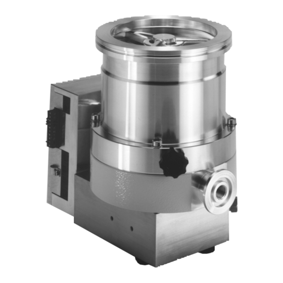
- Page 1 Betriebsanleitung • Operating Instructions Turbomolecular Drag Pumps With Electronic Drive Unit TC 600 TMH 261 / TMU 261 TMH 261 P / TMU 261 P...
-
Page 2: Table Of Contents
5.2. Turbopump Temperature Management....... 15 2. Understanding The Pumps 6. What To Do In Case Of Breakdowns ? ........16 TMH 261/TMU 261........4 2.1. Main Features..............4 7. Maintenance.......... 17 Proper Use ................4 7.1. Replacing The Lubricant Reservoir....... 17 Improper Use .............. -
Page 3: Safety Instructions
1. Safety Instructions Read and follow all instructions in this manual. 1.1. For Your Orientation Inform yourself regarding: On page 47 of this operating manual you will find a drawing – Hazards which can be caused by the pump; showing the connection options for the power unit and –... -
Page 4: Understanding The Pumps Tmh 261/Tmu 261
2.1. Main Features Proper use Turbopumps TMH/TMU 261 with the TC 600 form a complete – The Turbomolecular Pumps TMH 261/TMU 261 may only be unit. Voltage is supplied by the power unit (see used for the purpose of generating vacuum. -
Page 5: Differences Between The Pump Types
15%. um side immediately before connection. For fitting splinter shields please refer to “Fitting the splinter – On Turbopumps TMH 261/TMU 261 the lubricant reservoir shield” is already fitted and filled. – Where magnetic fields of > 6 mT are involved suitable The high vacuum side can be flanged directly to the vacuum shielding must be provided (available on request). -
Page 6: Fitting The Splinter Shield (Accessory)
Directly Flanging The Pump Fitting The Splinter Shield (Accessory) The turbopump can be flanged onto the vacuum chamber Insert the splinter shield in the high vacuum flange in such a vertically (0°) up to an angle of 90° maximum. way that the corrugation of the strainer points outwards. ➡... -
Page 7: Connecting The Cooling Unit
3.4. Connecting The Cooling Unit 3.6. Connecting The Casing Heating Unit The Turbopumps TMH 261/TMU 261 must be water or air The attainment of final pressures is accelerated when turbo- cooled. pumps and vacuum chambers are baked out. Air cooling may only be used where the ambient temperature Baking out is only practical on pumps with stainless steel is <... -
Page 8: Connecting The Electronic Drive Unit Tc 600
3.8. Connecting The Electronic Drive Unit TC 600 3.9. Installing The Power Unit The turbopump and the Electronic Drive Unit Voltage may only be supplied with the PFEIFFER PLEASE NOTE TC 600 are connected and together form a power units (Accessory). The use of other single unit. -
Page 9: Connecting The Remote Control Unit
3.10. Connecting The Remote Control Unit Remote control options for various functions are provided with the connection ”REMOTE” on the TC 600 via the 10 pole screw connector plug (maximum cable cross section 0.14-1.5 mm 2 /connection). Shielded cable should be used. Shielding is with the cable clamp on the plug side of the TC 600 connected to the TC casing. -
Page 10: Connecting The Serial Interface Rs 485
3.11. Connecting The Serial Interface RS 485 Connecting The RS 485 An external operating component (DCU 001 or DCU 200) or an Connection to a fixed bus system external computer can be connected via the connection ➡ Connect all units with D+ (pin 5 / RS 485) and D- (pin 7 / ”RS 485”... -
Page 11: Connections Diagram
3.12. Connections Diagram... -
Page 12: Operations
4. Operations 4.1. Before Switching ON 4.2. Switching ON ➡ Switch on the turbopump with switch S1 on the power unit. Sections 4.1. to 4.3. refer only to operating the pump in its condition on delivery, without the DCU operating unit. The –... -
Page 13: Switching Off And Venting
4.3. Switching OFF And Venting The power limitation serves to protect the pump against ther- mal over-oading. In order to avoid rotation speed fluctuations Before coming to rest after switching off, the turbopump must it is recommended to set, in rotation speed setting mode, the be vented in order to prevent contamination. -
Page 14: Operations With The Dcu 001/Dcu 200
4.6. Operations With The DCU 001/DCU 200 Motor, Turbopump When the pumping station is switched on and once the self Operations with the DCU 001 or DCU 200 should be carried out test has been successfully completed (duration approximate- in accordance with the relevant Operating Instructions ly 10 seconds), the turbopump is set in operation. -
Page 15: Switching Outputs
Switching Outputs Switching outputs 1 and 2 can be loaded with a maximum 24 V / 50 mA per output. The following functions are assigned to the switching outputs: Switching output 1: Active high when the rotation speed switchpoint is attained. The switchpoint for the turbopump is set at 80% of the nominal rotation speed. -
Page 16: What To Do In Case Of Breakdowns
6. What To Do In Case Of Breakdowns? Problem Possible Causes Remedy Pump doesn't start; • Power supply interrupted • Check fuse in the power unit None of the integrated LEDs • Check plug contacts on the mains glow on the TC 600 power unit •... -
Page 17: Maintenance
7. Maintenance No liability for personal injury nor material Remove locking cover and extract lubricant reservoir PLEASE NOTE damage will be accepted for damages and 90 Locking cover operational interruptions which have been 91 O-ring caused by improper maintenance; in addition, 92 Lubricant reservoir all guarantees become invalid. -
Page 18: Service
8. Service Do Make Use Of Our Service Facilities Decontaminate units before returning or possi- In the event that repairs are necessary a number of options ble disposal. Do not return any units which are are available to you to ensure any system down time is kept to microbiologically, explosively or radioactively a minimum: contaminated. -
Page 19: Technical Data
9. Technical Data Feature Unit TMH 261 TMU 261 TMTMH 261 P TMU 261 P Connection nominal diameter Inlet DN 100 ISO-K DN 100 CF-F DN 100 ISO-K DN 100 CF-F Outlet DN 25 ISO-KF/G 1/4“ DN 25 ISO-KF/G Venting connection G 1/8”... -
Page 20: Dimensions Diagram
9.1. Dimensions Diagram TMH/TMU 261 113.5 4xM8 DN 25 ISO-KF DN 100 CF-F DN 100 ISO-K Ø119 Ø138.5 1) Sealing gas valve only for ”P” version turbopumps ( see rating plate) -
Page 21: Spare Parts
10. Spare Parts Pos. Description Pieces Size Number Comments Ordering Quantity Spare Parts TMH/TMU 261 Set of seals PM 033 315 -T Rubber feet P 3695 700 ZE Remote plug P 0920 668 E USIT ring P 3529 133 -A O-ring Vi 38 x 3 P 4070 621 PV... -
Page 22: Accessories
11. Accessories Description Size Number Comments/ Order Quantity Operating Instructions Components for cooling Dirt trap R 3/8” P 4161 300 2R Recycled Water Cooling Unit TZK 400 230 V, 50 Hz PM Z01 245 PM 800 369 BN Air cooling 24 V DC PM Z01 252 PM 800 543 BN... -
Page 23: Drawings
Drawings Water cooling 3a Cooling water connection Electronic Drive Unit TC 600 42 Venting valve 8a Connecting cable, TC 600 – TPS/DCU 42a Control lead, venting valve/TC 600 20 Relay box, backing pump 42b Plug 20a Control lead, relay box/TC 600 46 Heating sleeve 105b Front panel 20b Connecting cable, backing pump... -
Page 24: Declaration Of Contamination
Declaration of Contamination of Vacuum Equipment and Components The repair and/or service of vacuum components will only be The manufacturer could refuse to accept any equipment carried out if a correctly completed declaration has been without a declaration. submitted. Non-completion will result in delay. This declaration can only be completed and signed by authorised and qualified staff: 1. -
Page 25: Manufacturer's Declaration
We certify conformity with EU Electromagnetic Compatibility Directive 89/336/EEC and EU Low Voltage Directive 73/23/EEC. Produkt/Product: TMH 261 / TMU 261 TMH 261 P / TMU 261 P Angewendete Richtlinien, harmonisierte Normen und angewendete, nationale Normen: Guidelines, harmonised standards, national standards in which have been applied: EN 292-1, EN 292-2, EN 294,... - Page 26 +27 / 11 315 5434, telefax +27 / 11 315 5882 Branch Office, Czech Republic Israel Taiwan Pfeiffer Vacuum Austria GmbH, Branch Prague Zvonarska 885 ODEM Scientific Applications Ltd. HAKUTO Taiwan Ltd. Hsinchu office No. 103, CZ-156 00 Praha 5 9 Hamazmera St., P.O.B.
Need help?
Do you have a question about the TMH 261 and is the answer not in the manual?
Questions and answers