Advertisement
Quick Links
WIRING DIAGRAM FOR S 100 FM BT CONTROL
MODULE AND UC 100 S CENTRAL UNIT
System with central unit
0
=
GROUND - Vcc
5
=
POWER SUPPLY 12 +Vcc
8
=
COMMUNICATIONS
9
=
COMMUNICATIONS
M
=
MICROPHONE AUDIO
C1 R
=
RIGHT CHANNEL 1
C1 L
=
LEFT CHANNEL 1
+
-
CABLE REF. W-8
MINIMUM SECTION
2X1 MM
6x0.25 MM
M
9
8
5
0
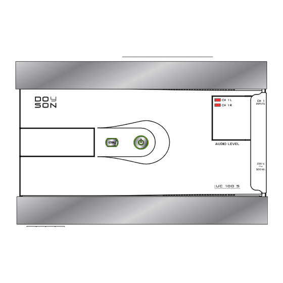
C1R
C1L
UC 100 S
2x0,75 mm.
MAINS 230 Vca.
ANTENNA CONNECTION: Conductor wire of 80 cm. In zones of
bad reception, connection to outdoor antenna it is highly recommended.
NOTE.- The
supports a máximum of 10 sound control modules and a maximum distance of 100 mts.of cable to the last element to be controlled.
UC 100 S
For higher installations, power supply units or a more powerful central unit would be required.
HOW TO PROGRAM THE SYSTEM:
Once all the system units are already installed, a zone number must be assigned to each control module as follows:
1st.- Keep the keys <> pressed during 4 seconds. The number "1" will be shown on the displays of ever y control module.
2nd.- Choose the control module you want to be the "zone 1" and press the On/Off key. The number "1" will be memorized as a zone number in
that control module.
3rd.- Now the rest of control modules will show the number "2" in their displays. Choose again which control module you want to be the "zone 2"
and press the On/Off key of that module.
4th- Repeat the process as many times as control modules/zones are in the installation.
5th- Once the zone assignment is finished, keep the control module on/off key pressed during 4 secondsin order to leave the "assingnment zone mode".
System with power supply unit
STEREO
ZONE
Speaker
Ref. SP 5
CABLE REF. W-2
MINIMUM SECTION
2X0.50 MM
-
+
0 5 8 9
M
R+ R- L- L+
ANT
C1L C1R
S 100 FM BT
For AUXILIARY CONNECTION of audio, TV, PC, etc. please
use 0 (ground) and C1L and C1R (Left and right channel 1)
STEREO
ZONE
Speaker
Ref. SP 5
CABLE REF. W-2
MINIMUM SECTION
2X0.50 MM
+
-
-
MAINS
5
0
0 5 8 9
M
R+ R- L- L+
C1L C1R
Power supply
unit
FA 12 BI
+
w w w. d oy s o n . c o m
S 100 FM BT Technical characteristics
Nr. of channels...................................1 stereo channel
Amplifier..............................................1.5+1.5W stereo
Bluetooth............................................A2DP transmission protocol
Minimum load impedance................8 ohms
Power supply......................................12Vcc/330mA
Stand-by power consumption........25mA
Operational power consumption..69mA
Connectors.........................................Strip terminals
Dimensions.........................................44 x 44 x 36mm depth
S o u n d & H o m e
A u t o m a t i o n
CONTROL
MODULE WITH
BLUETOOTH
S 100 FM
ON/OFF KEY
LCD DISPLAY
VOLUME, SCAN FM...
FM TURNER, AUDIO CHANNEL, AUX.
IN AND BLUETOOTH SELECTOR
MENU CONTROL KEY
MICROPHONE
AUXILIARY AUDIO INPUT
Advertisement

Related Manuals for Doyson S 100 FM BT


Summary of Contents for Doyson S 100 FM BT
- Page 1 WIRING DIAGRAM FOR S 100 FM BT CONTROL MODULE AND UC 100 S CENTRAL UNIT S o u n d & H o m e A u t o m a t i o n System with central unit System with power supply unit...
- Page 2 SLEEP MODE: While the control module is on, press repeatedly the appear on the display any more. your device "DOYSON-xxxxxx", select it to pair it MOD key until the function “SLEEP” is shown on the display. The The control module memorizes the last alarm clock setting if no new switch off time can be set by pressing the on/off key repeatedly (time features are introduced.
Need help?
Do you have a question about the S 100 FM BT and is the answer not in the manual?
Questions and answers