Table of Contents
Advertisement
Advertisement
Table of Contents

Related Manuals for Swan Analytical Instruments AMI Silitrace


Summary of Contents for Swan Analytical Instruments AMI Silitrace
- Page 1 AMI Silitrace Version 6.31 and higher A-96.250.811 / 091017...
- Page 2 SWAN representative, or the manufacturer: SWAN ANALYTISCHE INSTRUMENTE AG Studbachstrasse 13 8340 Hinwil Switzerland Internet: www.swan.ch E-mail: support@swan.ch Document Status Monitor AMI Silitrace Operator’s Manual Title: A-96.250.811 Revision Issue Okt. 2015 First Edition Aug. 2016 Update to FW Release 6.20, Mainboard Rev. 2.5 Mar.
-
Page 3: Table Of Contents
AMI Silitrace ........ - Page 4 AMI Silitrace Operation ......... . .
-
Page 5: A-96.250.811 / 091017
AMI Silitrace Safety Data sheets ........ -
Page 6: Safety Instructions
AMI Silitrace Safety Instructions AMI Silitrace - Operator’s Manual This document describes the main steps for instrument setup, oper- ation and maintenance. Safety Instructions General The instructions included in this section explain the potential risks associated with instrument operation and provide important safety practices designed to minimize these risks. -
Page 7: Warning Notices
AMI Silitrace Safety Instructions 1.1. Warning Notices The symbols used for safety-related notices have the following sig- nificance: DANGER Your life or physical wellbeing are in serious danger if such warnings are ignored. Follow the prevention instructions carefully. WARNING Severe injuries or damage to the equipment can occur if such warnings are ignored. -
Page 8: General Safety Regulations
AMI Silitrace Safety Instructions Warning Signs The importance of the warning signs in this manual. Electrical shock hazard Corrosive Harmful to health Flammable Warning general Attention general 1.2. General Safety Regulations Legal The user is responsible for proper system operation. All precau- tions must be followed to ensure safe operation of the instrument. - Page 9 AMI Silitrace Safety Instructions WARNING Risk of Electrical Shock If proper operation is no longer possible, the instrument must be disconnected from all power lines, and measures must be taken to prevent inadvertent operation. To prevent from electrical shock, always make sure that the ground wire is connected.
-
Page 10: Product Description
Product Description Product Description 2.1. Description of the System Application The AMI Silitrace is a complete monitoring system for the automatic, continuous measurement of the dissolved silica content in water Range steam cycles or demineralizer plants. Photometrical The determination of silica is done by the photometric analysis of molybdate blue at 815 nm. - Page 11 AMI Silitrace Product Description Grab sample Easy to use grab sample function. Signal Two signal outputs programmable for measured values (freely scal- able, linear, bilinear, log) or as continuous control output (control Outputs parameters programmable). Current loop: 0/4–20 mA Maximal burden: 510 Ohm Third signal output available as an option.
- Page 12 5 and standard is pumped through the photometer. NOTICE: The fluidic scheme shows the single-stream variant of the AMI Silitrace. The dual-stream variant is fitted with a different flow cell block and a channel selector valve (see Silitrace Dual-Stream, p.
- Page 13 AMI Silitrace Product Description Grab sample bottle Reagent 2 Standard bottle Reagent 3 Photometer module Reagent 4 Reaction chamber Sample inlet Cuvette Sample outlet Cuvette de-aeration Flow meter Sample outlet (siphon tube) Flow regulating valve Inlet from reaction chamber Zero calibration valve...
-
Page 14: Instrument Specification
AMI Silitrace Product Description 2.2. Instrument Specification Power Supply Voltage: 100–240 VAC (± 10%) 50/60 Hz (± 5%) DC version not available Power consumption: max. 50 VA Transmitter Electronics housing Aluminium with a protection degree of specifications IP 66 / NEMA 4X Ambient temperature: -10 to +50 °C... - Page 15 AMI Silitrace Product Description Dimensions Panel: stainless steel Dimensions: 400x850x150 mm Screws: 8 mm Weight: 16.0 kg 400 mm / 15¾” 13 mm / ½” 374 mm / 14¾” Exit Enter AMI SILITRACE Ozone Monitor Trace SiO Process Analyzer A-96.250.811 / 091017...
-
Page 16: Instrument Overview
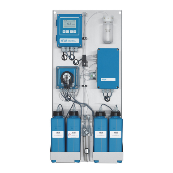
AMI Silitrace Product Description 2.3. Instrument Overview Panel Flow meter Standard bottle Sample inlet Grab sample bottle Sample outlet Solenoid valve for zero Reagent 4 calibration Reagent 3 Photometer module Reagent 2 6-way valve Reagent 1 Flow regulating valve Peristaltic pump... -
Page 17: Installation
AMI Silitrace Installation Installation 3.1. Installation Checklist Check Instrument’s specification must conform to the National Electri- cal Code, all state and local codes, and all plant codes and stan- dards for electrical equipment. 100–240 VAC (± 10%), 50/60 Hz (± 5%) power outlet with On site ground connection and 50 VA. -
Page 18: Mounting Of Instrument Panel
AMI Silitrace Installation 3.2. Mounting of Instrument Panel The first part of this chapter describes the preparing and placing of the instrument for use. The instrument must only be installed by trained personnel. Mount the instrument in vertical position. -
Page 19: Connect Sample And Waste
AMI Silitrace Installation 3.3. Connect Sample and Waste 3.3.1 AMI Silitrace OXYCON ON-LINE SILCA OXYCON ON-LINE SILCA OXYCON ON-LINE SILCA OXYCON ON-LINE SILCA AMI SILICA REAGENT 3 AMI SILICA REAGENT 4 AMI SILICA REAGENT 1 AMI SILICA REAGENT 2 Sample inlet... -
Page 20: Ami Silitrace Dual-Stream
AMI Silitrace Installation 3.3.2 AMI Silitrace Dual-Stream OXYCON ON-LINE SILCA OXYCON ON-LINE SILCA OXYCON ON-LINE SILCA OXYCON ON-LINE SILCA AMI SILICA REAGENT 3 AMI SILICA REAGENT 4 AMI SILICA REAGENT 1 AMI SILICA REAGENT 2 Sample inlet channel 1 Compression ferrule... -
Page 21: Electrical Connections
AMI Silitrace Installation 3.4. Electrical Connections WARNING Risk of electrical shock. Do not perform any work on electrical components if the trans- mitter is switched on. Failure to follow safety instructions could result in serious injury or death. Always turn off AC power before manipulating electric parts. - Page 22 AMI Silitrace Installation WARNING External Voltage. External supplied devices connected to relay 1 or 2 or to the alarm relay can cause electrical shocks Make sure that the devices connected to the following con- tacts are disconnected from the power before resuming in- stallation.
-
Page 23: Connection Diagram
AMI Silitrace Installation 3.4.1 Connection Diagram CAUTION Use only the terminals shown in this diagram, and only for the mentioned purpose. Use of any other terminals will cause short circuits with possible corresponding consequences to material and personnel. A-96.250.811 / 091017... -
Page 24: Power Supply
Mains cable to comply with standards IEC 60227 or IEC 60245; flammable rating FV1 Mains equipped with an external switch or circuit-breaker – near the instrument – easily accessible to the operator – marked as interrupter for AMI Silitrace A-96.250.811 / 091017... -
Page 25: Relay Contacts
AMI Silitrace Installation 3.5. Relay Contacts 3.5.1 Input NOTICE: Use only potential-free (dry) contacts. The total resistance (sum of cable resistance and resistance of the relay contact) must be less than 50 Ω. Terminals 16/42 For programming see “Program List and Explanation”... -
Page 26: Relay 1 And 2
AMI Silitrace Installation 3.5.3 Relay 1 and 2 NOTICE: Max. load 1 A/250 VAC Relay 1 and 2 can be configured as normally open or as normally closed. Standard for both relays is normally open. To configure a Relay as normally closed, set the jumper in the upper position. - Page 27 AMI Silitrace Installation CAUTION Risk of damage of the relays in the AMI Transmitter due to heavy inductive load. Heavy inductive or directly controlled loads (solenoid valves, dosing pumps) may destroy the relay contacts. To switch inductive loads > 0.1 A use an AMI relay box avail- able as an option or suitable external power relays.
-
Page 28: Signal Outputs
AMI Silitrace Installation 3.6. Signal Outputs 3.6.1 Signal Output 1 and 2 (current outputs) NOTICE: Max. burden 510 Ω. If signals are sent to two different receivers, use signal isolator (loop isolator). Signal output 1: Terminals 14 (+) and 13 (-) -
Page 29: Signal Output 3
AMI Silitrace Installation 3.7.1 Signal Output 3 Terminals 38 (+) and 37 (-). Requires the additional board for the third signal output 0/4–20 mA. The third signal output can be operated as a current source or as a current sink (switchable via switch [A]). For detailed information see the corresponding installation instruction. -
Page 30: Hart Interface
AMI Silitrace Installation 3.7.3 HART Interface Terminals 38 (+) and 37 (-). The HART interface PCB allows for communication via the HART protocol. For detailed information, consult the HART manual. HART Interface PCB 3.7.4 USB Interface The USB Interface is used to store Logger data and for Firmware upload. -
Page 31: Instrument Setup
Start-up Procedure The following table lists all necessary steps for a successful com- missioning of the AMI Silitrace. Additionally, the expected result and corrective actions are specified for each step. NOTICE: It is important to verify the result of each step before proceeding with the next step. - Page 32 AMI Silitrace Instrument Setup Step Expected result Corrective action No errors are displayed As soon as the reaction Resolve all pending errors apart from E008 chamber has reached its “SilTrace temp low” operating temperature, E008 automatically disappears If there are other...
-
Page 33: Prepare Reagents
100 ppb Stock solution From the stock solution you can produce your own standard. Stan- dards from 10 to 1000 ppb can be used for the AMI Silitrace. 100 ppm SWAN does not recommend to mix your own standard! By default the instrument is programmed for a standard of 100 ppb. - Page 34 AMI Silitrace Instrument Setup Standard During a calibration or verification approximately 15 ml standard is consumed. Therefore a standard bottle lasts for 3 months at default consumption interval settings. The default interval settings are: Start time: 06:00:00 Monday: Verification All other days: Off Screw the standard bottle to the right bottle holder.
-
Page 35: Switch On Power
AMI Silitrace Instrument Setup 4.4. Switch on Power Open the sample tap and switch on the instrument. INIT 0.0 °C 5.0 l/h After switching on, the instrument starts to warm up the reaction chamber. During the warm-up phase, the display shows <INIT>... - Page 36 AMI Silitrace Instrument Setup AMI Silitrace Flow regulating valve for Dual-Stream channel 1 Flow regulating valve for channel 2 Overflow Channel selector valve 1 Open the flow regulating valves (A and A 2 Adjust the sample flow to 5–10 l/h.
-
Page 37: Activate The Peristaltic Pump
AMI Silitrace Instrument Setup 4.6. Activate the Peristaltic pump The occlusion frames of the peristaltic pump are opened during transport and storage. This prevents the pump tubes from sticking together at the pressure points. 1 Turn the occlusion frames [B] clockwise until they snap in to ac- tivate the peristaltic pump. -
Page 38: Programming
Switching time 20 Min 6 Press [Exit], choose <Save> “Yes” Confirm with [Enter]. Channels With the AMI Sample Sequencer connected, the AMI Silitrace can be operated in the following 3 different modes. internal fieldbus external 1 Navigate to menu <Installation>/ Multi-Channel 5.1.6... -
Page 39: Final Tests
AMI Silitrace Instrument Setup 4.8. Final Tests Pending errors Resolve all pending errors, see Troubleshooting, p. Visual check Carefully pull out the cuvette [C] from the photometer module and open the cover [B]. Check that there are no air bubbles in the reac- of reaction tion chamber [D]. - Page 40 AMI Silitrace Instrument Setup Photometer Select <Diagnostics>/<Sensors>/<SilTrace>/<Photometer>. raw value Check if the photometer raw value follows a fill/empty pattern. See example below: While the cuvette is being filled, an unstable raw value is normal. Once the cuvette is completely filled, the raw value must remain stable.
- Page 41 AMI Silitrace Instrument Setup Standard Manually start a standard calibration (Calibration, p. 51), then re- view the calibration factor in <Diagnostics>/<Sensors>/<Cal. His- Calibration tory>. The calibration factor must be between 0.5 and 2.0. If this check fails: Check if the programmed concentration matches the reference value of the standard solution ...
-
Page 42: Operation
AMI Silitrace Operation Operation 5.1. Keys Exit Enter to exit a menu or command (rejecting any changes) to move back to the previous menu level to move DOWN in a menu list and to decrease digits to move UP in a menu list and to increase digits... -
Page 43: Display
AMI Silitrace Operation 5.2. Display 15:20:18 15:10:52 5 l/h 45.1 °C INIT Warming up the reaction chamber normal operation HOLD input closed or cal delay: Instrument on hold (shows status of signal outputs). input closed: control/limit is interrupted (shows status of signal outputs). - Page 44 ] key. Active measurement Position of valve ~ No sample flow n Measurement not valid x Sample stream inactive (only visible if a Sample Sequencer is connected to the AMI Silitrace and measuring mode <internal> is selected). A-96.250.811 / 091017...
-
Page 45: Software Structure
AMI Silitrace Operation 5.3. Software Structure Main Menu Messages Diagnostics Maintenance Operation Installation Menu Messages 1 Messages Reveals pending errors as well as an event history Pending Errors (time and state of events that have occurred at an Maintenance List earlier point of time). -
Page 46: Changing Parameters And Values
AMI Silitrace Operation 5.4. Changing Parameters and values Changing The following example shows how to change the logger interval: parameters 1 Select the parameter you want to Sensors Logger 5.1.2 4.4.1 change. Sensor type FOME Log interval 30 min 2 Press [Enter] Disinf. -
Page 47: Grab Sample Measurement
AMI Silitrace Operation 5.5. Grab Sample Measurement NOTICE: The grab sample function is not suitable for quality assurance of the instrument. Select Menu 4.1 (<Operation>/<Grab Sample>) and follow the in- structions on the display. Relay status during grab sample measurement: ... - Page 48 AMI Silitrace Operation Grab Sample 4.1.5 State xxxx Progress <Enter> to stop Grab Sample 4.1.5 State xxxx Cycle Timer 10 sec <Enter> to stop Grab Sample 4.1.5 State xxxx Cycle Progress <Enter> to stop 6 Press [Enter] to finish the grab Grab Sample 4.1.5...
-
Page 49: Maintenance
AMI Silitrace Maintenance Maintenance 6.1. Maintenance Table Monthly or less Replace reagents. frequent Every 2–3 months Check standard solution and exchange if necessary. Semiannual Exchange pump tubes. Perform a calibra- tion after exchanging the pump tubes. By occurrence E020, FOME dirty. Clean the photometer... -
Page 50: Refill Or Replace Reagents
AMI Silitrace Maintenance 6.3. Refill or Replace Reagents The liquid level in container 4 is monitored. The following messag- es are displayed: Container almost Maintenance E065 - Reagents low and the empty remaining reagent volume in % (starting at 17 % = 340 ml). - Page 51 AMI Silitrace Maintenance Reagent Each 2 liter reagent canister will last for approximately 1 month of operation if reagent saving is switched off or up to three months if consumption reagent saving is switched on (see 4.2.3, p. 85). NOTICE: Excessive use of the flush/fill function or frequent flow interruptions will shorten this period.
- Page 52 AMI Silitrace Maintenance Preparation NOTICE: Please consider the following points when preparing new reagents: • Reagent 3, Oxalic Acid dissolves very slowly, we therefore recommend to prepare Reagent 3 first. • Reagent 1, add Sodium hydroxide (Reagent 1b) first. • Before refilling rinse all containers well with demineralized water.
-
Page 53: Calibration
AMI Silitrace Maintenance 6.4. Calibration Select Menu 3.1 <Maintenance>/<Calibration> and follow the in- structions on the display. Relay status during calibration: Signal outputs are on hold All limits are switched off Calibration 4.1.5 Connect the standard bottle to marked holder <Enter>... -
Page 54: Verification
AMI Silitrace Maintenance 6.5. Verification Select Menu 3.2 <Maintenance>/<Verification> and follow the in- structions on the display. Relay status during verification: Signal outputs are on hold All limits are switched off Verification 4.1.5 Connect the standard bottle to marked holder <Enter>... -
Page 55: Zero
AMI Silitrace Maintenance 6.6. Zero Select Menu 3.2 <Maintenance>/<Zero> and follow the instructions on the display. Relay status during zero: Signal outputs are on hold All limits are switched off Zero 3.2.1 State xxxx Progress <Enter> to stop Zero 3.2.1... -
Page 56: Replace The Pump Tubes
AMI Silitrace Maintenance 6.7. Replace the Pump Tubes The pump tubes [D] of the peristaltic pump are exposed to a mini- mal wear. It is therefore recommended to exchange the pump tubes semiannually. NOTICE: it is highly recommended to replace all pump tubes at once. - Page 57 AMI Silitrace Maintenance Dismount The pump tubes can easily be dismounted and mounted. Proceed as follows: pump tubes Pump housing Occlusion frame open Rotor Pump tube Pump inlet Pump outlet 1 Switch off the instrument according to instructions in Stop of Operation for Maintenance, p.
-
Page 58: Fill System
AMI Silitrace Maintenance 7 Install the sample tube and all reagent tubes (see Replace the Pump Tubes, p. 54). 8 Push the occlusion frames onto the rotor. 9 Lock the occlusion frames. 10 Put suction lances into the corresponding reagent container. -
Page 59: Clean The Photometer
AMI Silitrace Maintenance 6.9. Clean the Photometer To clean the photometer, flush it with 5% ammonia solution. 1 Fill a beaker with 5% ammonia solution. 2 Place all suction lances in the beaker. 3 Navigate to menu <Maintenance>/<Service>/<Fill system>. 4 Press [Enter]. -
Page 60: Troubleshooting
AMI Silitrace Troubleshooting Troubleshooting 7.1. Error List Error Non-fatal Error. Indicates an alarm if a programmed value is ex- ceeded. Such Errors are marked E0xx (bold and black). Fatal Error (blinking symbol) Control of dosing devices is interrupted. The indicated measured values are possibly incorrect. - Page 61 AMI Silitrace Troubleshooting Error Description Corrective action – Check process E001 Si 1 Alarm high – Check programmed value, see 5.3.1.x.1, p. 96 – Check process E002 Si 1 Alarm low – Check programmed value, see 5.3.1.x.22, p. 96 – Check process...
- Page 62 AMI Silitrace Troubleshooting Error Description Corrective action – Check ambient temperature (min 5°C) E012 Temp. Timeout – Close the photometer lid – Heater defective, call service. – Check case/environment temperature E013 Case Temp. high – Check programmed value, see 5.3.1.42, p. 97 –...
- Page 63 AMI Silitrace Troubleshooting Error Description Corrective action – Unsuccessful peak detection can be E021 Signal Timeout caused by: 1) interrupted light path 2) no water/too much air in the reaction chamber – Check if reaction chamber is clogged, replace it if necessary, see Replace the reaction chamber, p.
- Page 64 AMI Silitrace Troubleshooting Error Description Corrective action – Check inlet pressure E033 Sample Flow 1 low (multi-channel instru- – Re-adjust sample flow ments) – Check programmed value, see 5.3.1.32.2, p. 97 – Check inlet pressure E034 Sample Flow 2 low (multi-channel instru- –...
-
Page 65: Replace The Reaction Chamber
AMI Silitrace Troubleshooting 7.2. Replace the reaction chamber Replacing the reaction chamber may be necessary if: Error 12, <Temp. time out> is shown. Error 21, <Signal time out> is shown. Cover fixing screws Photometer module cover Cuvette Connection panel To replace the reaction chamber proceed as follows:... - Page 66 AMI Silitrace Troubleshooting 7 Remove the reaction chamber from the photometer housing. Install the new 1 Insert the new reaction chamber into the photometer housing and tighten the fixing screw [G]. reaction chamber 2 Put the cover [B] onto the photometer unit and tighten the 4 cover fixing screws [A].
-
Page 67: Replace The 6-Way Valve
AMI Silitrace Troubleshooting 7.3. Replace the 6-Way Valve CAUTION Never loosen the 4 allen screws [D] visible on the 6-way valve body. Remove the Replacing the 6-way valve may be necessary if: 6-way valve Error 25 <Rovalve> is shown. 6-way valve body Valve fixing screw Allen key 2.5 mm... - Page 68 AMI Silitrace Troubleshooting Install the 6-way valve Blind plug Positioning screw 6-way valve Driving slot Fixing screw Guiding hole Valve shaft with driving pin Seal all unused Inputs with the enclosed blind plugs [A]. Proceed as follows: 1 Make sure that the valve shaft with driving pin [D] is aligned with the driving slot [F].
-
Page 69: Replace The Cuvette
AMI Silitrace Troubleshooting 7.4. Replace the Cuvette Replacing the cuvette may be necessary if: Error 20 <FOME Dirty> is shown. Photometer module Cuvette Photometer module Cuvette To exchange the cuvette proceed as follows: 1 Shut down the Instrument according to Stop of Operation for Maintenance, p. -
Page 70: Replace The Reagent Tubes
AMI Silitrace Troubleshooting 7.5. Replace the Reagent Tubes Tube numbering A-96.250.811 / 091017... - Page 71 AMI Silitrace Troubleshooting from Length Canister 1 [J] Peristaltic pump [T] inlet 2 1200 mm Canister 2 [K] Peristaltic pump [T] inlet 3 1200 mm Canister 3 [L] Peristaltic pump [T] inlet 4 1200 mm Canister 4 [M] Peristaltic pump [T] inlet 5...
-
Page 72: Cleaning The Solenoid Valve
AMI Silitrace Troubleshooting 7.6. Cleaning the solenoid valve Disassemble The solenoid valve should be disassembled if it does not switch anymore or if it is clogged. the solenoid valve 1 Switch off the instrument according to instructions in Stop of Operation for Maintenance, p. - Page 73 AMI Silitrace Troubleshooting NOTICE: The O-rings inside the valve body may stick on the flow cell and fall down if the valve body is removed. 5 Remove the valve body from the flow cell. 6 Remove the base plate (G) with a screw driver size 0 (F).
-
Page 74: Replacing Fuses
AMI Silitrace Troubleshooting 7.7. Replacing Fuses WARNING External Voltage. External supplied devices connected to relay 1 or 2 or to the alarm relay can cause electrical shocks. Make sure that the devices connected to the following con- tacts are disconnected from the power before resuming in- stallation. -
Page 75: Program Overview
AMI Silitrace Program Overview Program Overview For explanations about each parameter of the menus see Program List and Explanations, p. Menu 1 Messages informs about pending errors and mainte- nance tasks and shows the error history. Password protection possible. No settings can be modified. -
Page 76: Diagnostics (Main Menu 2)
AMI Silitrace Program Overview 8.2. Diagnostics (Main Menu 2) Identification Designation AMI Silitrace * Menu numbers 2.1* Version V6.31-10/17 Peripherals PeriClip 2.1.3* RoValve SiliTrace Factory Test Instrument 2.1.3.1* 2.1.4* Motherboard Operating Time Years / Days / Hours / Minutes / Seconds 2.1.4.1*... -
Page 77: Maintenance (Main Menu 3)
AMI Silitrace Program Overview Cycle diagnostics P2P period 2.2.4.1* 2.2.4* P2P counter Pump speed Adjust cycle Sample Sample ID 2.3.1* 2.3* Sample flow Sample flow 2.3.2.1* 2.3.2* (Raw value) I/O State Alarm Relay 2.4.1* 2.4* Relay 1 and 2 2.4.2*... -
Page 78: Operation (Main Menu 4)
AMI Silitrace Program Overview Pump 3.5.9* Set Time (Date), (Time) 3.6* 8.4. Operation (Main Menu 4) Grab Sample * Menu numbers 4.1* Sensors Filter Time Const. 4.2.1* 4.2* Hold after Cal. 4.2.2* Reagents saving 4.2.3* Relay Contacts Alarm Relay Alarm Si 1 Alarm High 4.3.1.1.1*... -
Page 79: Installation (Main Menu 5)
AMI Silitrace Program Overview 8.5. Installation (Main Menu 5) Sensors Meas parameters Cal./Verif. Standard 5.1.1.1.1* 5.1* 5.1.1 5.1.1.1* Parameters Start time 5.1.1.1.2* Monday Tuesday Wednesday Thursday Friday Saturday Sunday Background Background 5.1.1.2.1* 5.1.1.2* Auto-Zero Auto-Zero 5.1.1.3.1* 5.1.1.3* Start time 5.1.1.3.2* Cuvette Factor 5.1.1.4*... -
Page 80: Output/Control
AMI Silitrace Program Overview Hysteresis 5.3.2.402–5.3.3.402* * Menu numbers Delay 5.3.2.50–5.3.3.50* Input Active 5.3.4.1* 5.3.4* Signal Outputs 5.3.4.2* Output/Control 5.3.4.3* Fault 5.3.4.4* Delay 5.3.4.5* Miscellaneous Language 5.4.1* 5.4* Set defaults 5.4.2* Load Firmware 5.4.3* Password Messages 5.4.4.1* 5.4.4* Maintenance 5.4.4.2* Operation 5.4.4.3*... -
Page 81: Program List And Explanations
AMI Silitrace Program List and Explanations Program List and Explanations 1 Messages 1.1 Pending Errors 1.1.5 Provides the list of active errors with their status (active, acknowl- edged). If an active error is acknowledged, the alarm relay is active again. Cleared errors are moved to the Message list. - Page 82 AMI Silitrace Program List and Explanations FOME mean Absorbance: A = -log zero FOME Mean: Raw signal in V, measured during T2 (pump stopped) to calculate the concentration. 2.2.2 Miscellaneous: Case Temp: Shows the current temperature in °C inside the transmitter.
- Page 83 AMI Silitrace Program List and Explanations Calibration, verification, zero or grab sample procedure CAL INIT A calibration, verification, zero or grab sample mea- surement has been initiated. CAL END A calibration, verification, zero or grab sample mea- surement has finished or been aborted.
- Page 84 AMI Silitrace Program List and Explanations 2.2.4 Cycle diagnostics P2P Diagram Peak Peak P2P period: interval between the last two peaks P2P counter: shows the time of the current P2P period Pump speed: shows the current speed code of the pump (0 – 30) Adjust cycle: when the pump speed exceeds a given time limit 3...
-
Page 85: Maintenance
AMI Silitrace Program List and Explanations 3 Maintenance 3.1 Calibration 3.1.5 During calibration, a solution of known silica concentration (stan- dard) is measured and the measuring value is compared with the reference value of the standard (set in 5.1.1.1, p. - Page 86 Active or inactive Magnetic valve 1: Zero calibration valve Magnetic valve 2: Channel selector valve (AMI Silitrace Dual-Stream) At the absence of any key activities, the instrument will switch back to normal mode after 20 min. If you quit the menu, all simulated val- ues will be reset.
-
Page 87: Operation
AMI Silitrace Program List and Explanations 4 Operation 4.1 Grab Sample 4.1.5 Starts a grab sample measurement. See Grab Sample Measure- ment, p. 4.2 Sensors 4.2.1 Filter Time Constant: Used to damp noisy signals. The higher the filter time constant, the slower the system reacts to changes of the measured value. - Page 88 AMI Silitrace Program List and Explanations 4.3 Relay Contacts Relay Contacts, p. 23 4.4 Logger The instrument is equipped with an internal logger. The logger data can be copied to a PC with an USB stick if the option USB interface is installed.
-
Page 89: Installation
AMI Silitrace Program List and Explanations 5 Installation 5.1 Sensors 5.1.1 Meas. Parameters 5.1.1.1 Cal./Verif. 5.1.1.1.1 Standard: The default standard is 100 ppb. During a calibration or verification 15 ml standard is consumed. Therefore a standard bottle lasts for 3 months at default interval settings. - Page 90 AMI Silitrace Program List and Explanations 5.1.1.2 Reag, Background 5.1.1.2.1 Reag. Background: Enter the known basic pollution of the reagents. The entered value will be subtracted form the measuring value. 5.1.1.3 Auto-Zero 5.1.1.3.1 Auto-Zero: Activate or deactivate the automatic daily zero calibra- tion.
- Page 91 In the example below, only the sample streams 2, 4 and 6 are measured, whereas the samples streams 1, 3 and 5 are switched off. Sample streams which are switched off are marked with an “x” behind the measuring value on the AMI Silitrace display. SEQUENCER Mode Fieldbus The AMI Silitrace is controlled via fieldbus.
- Page 92 AMI Silitrace Program List and Explanations Example: If sample stream 1 of the Sample Sequencer is active, the AMI Sili- trace measures the sample stream 1 until the Sample Sequencer changes to the next programmed channel. In the example below, the sample stream 3 (CH3) highlighted in green will be measured as soon as the switching time has elapsed.
- Page 93 Parameter: Assign one of the process values to the signal output. Available values: Sample Flow Si1 Si2 (AMI Silitrace Dual-Stream) 5.2.1.2 Current Loop: Select the current range of the signal output. Make sure the connected device works with the same current range.
- Page 94 AMI Silitrace Program List and Explanations As process The process value can be represented in 3 ways: linear, bilinear or logarithmic. See graphs below. values [mA] 0 / 4 linear X Measured value bilinear [mA] 0 / 4 1’000 10’000 X Measured value (logarithmic) A-96.250.811 / 091017...
- Page 95 AMI Silitrace Program List and Explanations 5.2.1.40 Scaling: Enter beginning and end point (Range low & high) of the linear or logarithmic scale. In addition, the midpoint for the bilinear scale. Parameter Sample flow: 5.2.1.40.10 Range low: 0–50 l/h 5.2.1.40.20 Range high: 0–50 l/h...
- Page 96 AMI Silitrace Program List and Explanations Ziegler-Nichols method for the optimization of a PID controller: Parameters: Setpoint, P-Band, Reset time, Derivative time Response to maximum control output = 1.2/a Tangent on the inflection point = 2L Time = L/2 The point of intersection of the tangent with the respective axis will result in the parameters a and L.
- Page 97 AMI Silitrace Program List and Explanations 5.2.1.43.3 Reset time: The reset time is the time till the step response of a sin- gle I-controller will reach the same value as it will be suddenly reached by a P-controller. Range: 0–9’000 sec 5.2.1.43.4...
- Page 98 AMI Silitrace Program List and Explanations 5.3 Relay Contacts 5.3.1 Alarm Relay: The alarm relay is used as cumulative error indicator. Under normal operating conditions the contact is active. The contact is inactive at: Power loss Detection of system faults like defective sensors or electronic parts ...
- Page 99 AMI Silitrace Program List and Explanations 5.3.1.32 Sample Flow: Define at which sample flow a flow alarm should be issued. 5.3.1.32.1 Flow Alarm: Program if the alarm relay should be activated if there is a flow alarm. Choose between yes or no. The flow alarm will al- ways be indicated in the display, pending error list, saved in the message list and the logger.
- Page 100 1 First select the functions as: - Limit upper/lower, - Control upwards/downwards, - Timer - Fieldbus - Channel Selection (AMI Silitrace Dual-Stream) 2 Then enter the necessary data depending on the selected func- tion. 5.3.2.1 Function = Limit upper/lower: When the relays are used as upper or lower limit switches, program the following: 5.3.2.20...
- Page 101 AMI Silitrace Program List and Explanations 5.3.2.22 Parameter: Choose on of the following process values. Sample flow Si1 Si2 (AMI Silitrace Dual-Stream) 5.3.2.32 Settings: Choose the respective actuator: Time proportional Frequency Motor valve 5.3.2.32.1...
- Page 102 AMI Silitrace Program List and Explanations 5.3.2.32.4 Control Parameters Range for each Parameter same as 5.2.1.43, p. 94 5.3.2.1 Function = Timer: The relay will be activated repetitively depending on the pro- grammed time scheme. 5.3.2.24 Mode: Operating mode (interval, daily, weekly) 5.3.2.24...
- Page 103 The relay will be switched via the Profibus input. No further param- eters are needed. 5.3.2.1 Function = Channel Selection: AMI Silitrace Dual-Stream: Relay 2 can be used to indicate which channel is selected. No fur- ther parameters are needed. Relay 2 inactive...
- Page 104 Input: The functions of the relays and signal outputs can be de- fined depending on the position of the input contact, i.e. no function, closed or open. AMI Silitrace Dual-Stream: If <Channel Selection> (5.1.2.2, p. 88) is set to “external”, the input is used to switch between channels 1 and 2.
- Page 105 AMI Silitrace Program List and Explanations 5.4 Miscellaneous 5.4.1 Language: Set the desired language. Language German English French Spanish 5.4.2 Set defaults: Reset the instrument to factory default values in three different ways: Set defaults Calibration In parts Completely Calibration: Sets calibration values back to default. All other values are kept in memory.
- Page 106 AMI Silitrace Program List and Explanations 5.4.7 Auto-Save: Determines whether the result of a manually started procedure (e. g. grab sample measurement) is automatically saved or discarded after 20 minutes without key input. Choose between <Yes> or <No>. The setting applies to the following procedures: ...
-
Page 107: Safety Data Sheets
AMI Silitrace Safety Data sheets Safety Data sheets A-85.420.860 Catalogue No.: AMI Silitrace Reagent 1a Product name: Ammonium molybdate tetrahydrate. A-85.420.860 Catalogue No.: AMI Silitrace Reagent 1b Product name: Sodium hydroxide A-85.420.860 Catalogue No.: AMI Silitrace Reagent 2 Product name: Sulphuric acid A-85.420.860... -
Page 108: Default Values
AMI Silitrace Default Values Default Values Operation: Sensors: Filter Time Const.:..............10 s Hold after Cal.:................. 720 s Reagents saving ................no Relay Contacts Alarm Relay ..........same as in Installation Relay 1 and 2 ..........same as in Installation Input.............. same as in Installation Logger: Logger Interval:............ - Page 109 AMI Silitrace Default Values Case temp. high: ..............65 °C Case temp. low:................. 0 °C Relay 1 and 2 Function:................limit upper Parameter:................... Si1 Setpoint: ................1.00 ppm Hysteresis:................5.0 ppb Delay ..................30 s If Function = Control upw. or dnw: Parameter:...................Si1...
- Page 110 AMI Silitrace Default Values Input: Active ................when closed Signal Outputs ................hold Output/Control ................off Fault....................no Delay..................10 s Miscellaneous Language:................English Set default:..................no Load firmware: ................no Password: ............for all modes 0000 Sample ID: ............... - - - - - - - - Line Break Detection ..............no...
-
Page 111: Index
AMI Silitrace Index Index ..... Alarm Relay Input ... Application Range... - Page 112 AMI Silitrace Index ....Safety Features Technical Data ... . – Sample Flow Terminals .
-
Page 113: Notes
AMI Silitrace Notes Notes A-96.250.811 / 091017... - Page 114 AMI Silitrace SWAN is represented worldwide by subsidiary companies and distributors. cooperates with independent representatives all over the world. SWAN Products Analytical Instruments for: High Purity Water Feedwater, Steam and Condensate Potable Water Pool and Sanitary Water Cooling Water Waste Water and Effluents Made in Switzerland A-96.250.811 / 091017...
Need help?
Do you have a question about the AMI Silitrace and is the answer not in the manual?
Questions and answers