Table of Contents
Advertisement
Advertisement
Table of Contents

Related Manuals for AutomationDirect D2-16ND3-2

Summary of Contents for AutomationDirect D2-16ND3-2
- Page 1 DL205 Installation and I/O Manual Manual Number: D2-INST-M...
- Page 3 This publication is based on information that was available at the time it was printed. At AutomationDirect we constantly strive to improve our products and services, so we reserve the right to make changes to the products and/or publications at any time without notice and without any obligation.
- Page 4 («activités à risque élevé»). La société AutomationDirect nie toute garantie expresse ou implicite d'aptitude à l'emploi en ce qui a trait aux activités à risque élevé.
- Page 5 DL205 I I/O MANUAL NSTALLATION AND Please include the Manual Number and the Manual Issue, both shown below, when communicating with Technical Support regarding this publication. Manual Number: D2-INST-M Issue: 2nd Edition Issue Date: 11/10 Publication History Issue Date Description of Changes 1st Edition 10/98 original edition...
-
Page 7: Table Of Contents
ABLE OF ONTENTS Chapter 1: Introduction Introduction ............1–2 The Purpose of this Manual . - Page 8 Table of Contents Marine Use ............2–9 Agency Approvals .
- Page 9 D2-16ND3-2, DC Input ........
- Page 10 Table of Contents F2-08AD-2 8-Channel Voltage Analog Input Module ..... .3–50 DL205 RTD and Thermocouple Modules ....... .3–52 F2-04RTD 4-Channel RTD Input Module .
- Page 11 Table of Contents Base Power Required ..........3–79 OFF to ON Response .
- Page 13 HAPTER HAPTER HAPTER NTRODUCTION In This Chapter... Introduction ......... . .1–2 Conventions Used .
-
Page 14: Chapter 1: Introduction
CPU-slot controllers or I/O controllers who are also using AutomationDirect DL205 I/O products. This manual will show the user how to install and wire the equipment. It provides specifications for input and output modules. It also helps to understand how to interface these products to other devices in a control system. -
Page 15: Conventions Used
Chapter 1: Introduction Conventions Used When you see the “notepad” icon in the left–hand margin, the paragraph to its immediate right will be a special note. The word NOTE in boldface will mark the beginning of the text. When you see the “exclamation mark” icon in the left–hand margin, the paragraph to its immediate right will be a warning. -
Page 16: Cpu-Slot Controllers
Chapter 1: Introduction CPU-Slot Controllers There are currently six “base controllers” or “I/O controllers available for the DL205 hardware. Five of these are actually slave controllers and one is a stand-alone controller. These controllers allow the use of industry proven DL205 I/O for general purpose distributed applications. -
Page 17: Dl205 System I/O Components
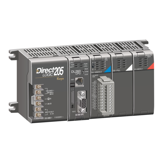
Chapter 1: Introduction DL205 System I/O Components Bases Four base sizes are available: 3 slot, 4 slot, 6 slot and 9 slot. One slot is for the DL205 Controller/Slave module, the remaining slots are for I/O modules. All bases include a built-in power supply. - Page 19 HAPTER HAPTER HAPTER NSTALLATION IRING PECIFICATIONS In This Chapter: Safety Guidelines ........2–2 Mounting Guidelines .
-
Page 20: Safety Guidelines
The protection provided by the equipment may be impaired if this equipment is used in a manner not specified in this manual. A listing of our international affiliates is available on our Web site: http://www.automationdirect.com WARNING: Providing a safe operating environment for personnel and equipment is your responsibility and should be your primary goal during system planning and installation. -
Page 21: Three Levels Of Protection
Chapter 2: Installation and Wiring Three Levels of Protection The publications mentioned provide many ideas and requirements for system safety. At a minimum, you should follow these regulations. Also, you should use the following techniques, which provide three levels of system control: •... -
Page 22: Emergency Power Disconnect
Chapter 2: Installation and Wiring Emergency Power Disconnect A properly rated emergency power disconnect should be used to power the PLC controlled system as a means of removing the power from the entire control system. It may be necessary to install a capacitor across the disconnect to protect against a condition known as “outrush”. This condition occurs when the output Triacs are turned off by powering off the disconnect, thus causing the energy stored in the inductive loads to seek the shortest distance to ground, which is often through the Triacs. -
Page 23: Mounting Guidelines
Chapter 2: Installation and Wiring Mounting Guidelines Before installing the PLC system you will need to know the dimensions of the components considered. The diagrams on the following pages provide the component dimensions to use in defining your enclosure specifications. Remember to leave room for potential expansion. NOTE: If you are using other components in your system, refer to the appropriate manual to determine how those units can affect mounting dimensions. -
Page 24: Panel Mounting And Layout
Chapter 2: Installation and Wiring Panel Mounting and Layout It is important to design your panel properly to help ensure the DL205 products operate within their environmental and electrical limits. The system installation should comply with all appropriate electrical codes and standards. It is important the system also conforms to the operating standards for the application to insure proper performance. -
Page 25: Enclosures
Automation Powerline Filter, for use with 120 VAC and 240 VAC, 1–5 Amps, is an excellent choice (can be located at www.automationdirect.com), however, you can use a filter of your choice. These units install easily between the power source and the PLC. -
Page 26: Environmental Specifications
Chapter 2: Installation and Wiring Environmental Specifications The following table lists the environmental specifications that generally apply to the DL205 system (CPU, Bases, I/O Modules). The ranges that vary for the Handheld Programmer are noted at the bottom of this chart. I/O module operation may fluctuate depending on the ambient temperature and your application. -
Page 27: Marine Use
Chapter 2: Installation and Wiring Marine Use American Bureau of Shipping (ABS) certification requires flame-retarding insulation as per 4-8-3/5.3.6(a). ABS will accept Navy low smoke cables, cable qualified to NEC “Plenum rated” (fire resistant level 4), or other similar flammability resistant rated cables. Use cable specifications for your system that meet a recognized flame retardant standard (i.e. -
Page 28: Installing Dl205 Bases
Chapter 2: Installation and Wiring Installing DL205 Bases Choosing the Base Type The DL205 system offers four different sizes of bases and three different power supply options. The following diagram shows an example of a 6-slot base. Power Wiring CPU Slot I/O Slots Connections Your choice of base depends on three things:... -
Page 29: Using Mounting Rails
Chapter 2: Installation and Wiring Using Mounting Rails The DL205 bases can also be secured to the cabinet by using mounting rails. You should use rails that conform to DIN EN standard 50 022. Refer to our catalog for a complete line of DIN rail, DINnectors and DIN rail mounted apparatus. -
Page 30: Installing Components In The Base
Chapter 2: Installation and Wiring Installing Components in the Base To insert components into the base: first slide the module retaining clips to the out position and align the PC board(s) of the module with the grooves on the top and bottom of the base. Push the module straight into the base until it is firmly seated in the backplane connector. -
Page 31: Base Wiring Guidelines
Chapter 2: Installation and Wiring Base Wiring Guidelines Base Wiring 110/220 VAC Base T erminal Strip The diagrams show the terminal connections located on the power supply of the DL205 bases. The base terminals 85 – 264 VAC can accept up to 16 AWG. You may be able to use larger wiring depending on the type of wire used, but 16 AWG is the recommended size. - Page 33 HAPTER HAPTER HAPTER I/O W IRING AND PECIFICATIONS In This Chapter: I/O Wiring Strategies ........3–2 I/O Modules Position, Wiring, and Specification .
-
Page 34: Chapter 3: I/O Wiring And Specification
Chapter 3: I/O Wiring and Specifications I/O Wiring Strategies The DL205 PLC system is very flexible and will work in many different wiring configurations. By studying this section before actual installation, you can probably find the best wiring strategy for your application. This will help to lower system cost, wiring errors, and avoid safety problems. -
Page 35: Powering I/O Circuits With The Auxiliary Supply
Chapter 3: I/O Wiring and Specifications Powering I/O Circuits with the Auxiliary Supply In some cases, using the built-in auxiliary +24VDC supply can result in a cost savings for your control system. It can power combined loads up to 300mA. Be careful not to exceed the current rating of the supply. -
Page 36: Powering I/O Circuits Using Separate Supplies
Chapter 3: I/O Wiring and Specifications Powering I/O Circuits Using Separate Supplies In most applications it will be necessary to power the input devices from one power source, and to power output loads from another source. Loads often require high-energy AC power, while input sensors use low-energy DC. -
Page 37: Sinking / Sourcing Concepts
Chapter 3: I/O Wiring and Specifications Sinking / Sourcing Concepts Before going further in the study of wiring strategies, you must have a solid understanding of “sinking” and “sourcing” concepts. Use of these terms occurs frequently in input or output circuit discussions. -
Page 38: I/O "Common" Terminal Concepts
DC supply connects to the common terminals. Some symbols you will see on the wiring labels, and their meanings are: AC supply DC supply AC or DC supply – D2-16ND3-2 Input Switch Output Load 3–6 DL205 Installation and I/O Manual, 2nd Edition... -
Page 39: Connecting Dc I/O To "Solid State" Field Devices
Chapter 3: I/O Wiring and Specifications Connecting DC I/O to “Solid State” Field Devices In the previous section on Sourcing and Sinking concepts, the DC I/O circuits were explained to sometimes only allow current to flow one way. This is also true for many of the field devices which have solid-state (transistor) interfaces. - Page 40 Chapter 3: I/O Wiring and Specifications In the next example a PLC sinking DC output point is connected to the sinking input of a field device. This is a little tricky, because both the PLC output and field device input are sinking type.
-
Page 41: Relay Output Guidelines
Chapter 3: I/O Wiring and Specifications Relay Output Guidelines Several output modules in the DL205 I/O family feature relay outputs: D2–04TRS, D2–08TR, D2–12TR, D2–08CDR, F2–08TR and F2–08TRS. Relays are best for the following applications: • Loads that require higher currents than the solid-state outputs can deliver •... - Page 42 Use the following table to help select a TVS or MOV suppressor for your application based on the inductive load voltage. Vendor / Catalog Suppressor Types Inductive Load Voltage Part Number AutomationDirect 8–channel TVS 24 VDC ZL–TD8–24 Transient Voltage Suppressors 8–channel TVS...
- Page 43 Chapter 3: I/O Wiring and Specifications Relay contacts wear according to the amount of relay switching, amount of spark created at the time of open or closure, and presence of airborne contaminants. However, there are some steps you can take to help prolong the life of relay contacts: •...
- Page 44 Chapter 3: I/O Wiring and Specifications For example, suppose a relay contact drives a load at 120VAC, 1/2 A. Since this example has an AC power source, first calculate the peak values: x 1.414, = 0.5 x 1.414 = 0.707 Amperes peak x 1.414 = 120 x 1.414 = 169.7 Volts peak...
-
Page 45: I/O Modules Position, Wiring, And Specification
Chapter 3: I/O Wiring and Specifications I/O Modules Position, Wiring, and Specification Slot Numbering The DL205 bases each provide different numbers of slots for use with the I/O modules. You may notice the bases refer to 3-slot, 4-slot, etc. One of the slots is dedicated to the CPU-slot controller, so you always have one less I/O slot. -
Page 46: Special Placement Considerations For Analog Modules
Chapter 3: I/O Wiring and Specifications Special Placement Considerations for Analog Modules In most cases, the analog modules can be placed in any slot. However, the placement can also depend on the type of CPU you are using and the other types of modules installed to the left of the analog modules. -
Page 47: Wiring The Different Module Connectors
Chapter 3: I/O Wiring and Specifications Wiring the Different Module Connectors There are two types of module connectors for the DL205 I/O. Some modules have normal screw terminal connectors. Other modules have connectors with recessed screws. The recessed screws help minimize the risk of someone accidentally touching active wiring. -
Page 48: I/O Wiring Checklist
Chapter 3: I/O Wiring and Specifications I/O Wiring Checklist Use the following guidelines when wiring the I/O modules in your system. 1. There is a limit to the size of wire the modules can accept. The table below lists the suggested AWG for each module type. -
Page 49: I/O Points Required For Each Module
Chapter 3: I/O Wiring and Specifications I/O Points Required for Each Module Each type of module requires a certain number of I/O points. This is also true for some specialty modules, such as analog, counter interface, etc.. DC Input Modules Number of I/O Pts. -
Page 50: Calculating The Power Budget
Chapter 3: I/O Wiring and Specifications Calculating the Power Budget Managing your Power Resource When you determine the types and quantity of I/O modules you will be using in the DL205 system it is important to remember there is a limited amount of power available from the power supply. - Page 51 Chapter 3: I/O Wiring and Specifications Power Consumed Power Consumed 24V Auxilliary 24V Auxilliary Device 5V (mA) Device 5V (mA) (mA) (mA) CPUs Combination Modules D2–230 D2–08CDR D2–240 Specialty Modules D2–250–1 H2–PBC D2–260 H2–ECOM DC Input Modules H2–ECOM100 D2–08ND3 H2–ECOM-F D2–16ND3–2 H2–ERM D2–32ND3(–2)
-
Page 52: Power Budget Calculation Example
Chapter 3: I/O Wiring and Specifications Power Budget Calculation Example The following example shows how to calculate the power budget for the DL205 system. Auxiliary Base # Module Type 5 VDC (mA) Power Source 24 VDC Output (mA) Available Base Power D2–09B–1 2600 CPU Slot... -
Page 53: Power Budget Calculation Worksheet
Chapter 3: I/O Wiring and Specifications Power Budget Calculation Worksheet This blank chart is provided for you to copy and use in your power budget calculations. Auxiliary Base # Module Type 5 VDC (mA) Power Source 24 VDC Output (mA) Available Base Power CPU Slot Slot 0... -
Page 54: Dl205 Digital Input Modules
Chapter 3: I/O Wiring and Specifications DL205 Digital Input Modules D2-08ND3, DC Input D2-16ND3-2, DC Input Inputs per Module Inputs per Module 16 (sink/source) 8 (sink/source) Commons per Module 2 isolated (8 I/O terminal 1 (2 I/O terminal points) Commons per Module... -
Page 55: D2-32Nd3, Dc Input
Chapter 3: I/O Wiring and Specifications D2–32ND3, DC Input Inputs per Module 32 (sink/source) Commons per Module 4 isolated (8 I/O terminal points / com) Input Voltage Range 20-28 VDC Peak Voltage 30 VDC ON Voltage Level 19 VDC minimum OFF Voltage Level 7 VDC maximum AC Frequency... -
Page 56: D2-32Nd3-2, Dc Input
Chapter 3: I/O Wiring and Specifications D2–32ND3–2, DC Input Inputs per Module 32 (Sink/Source) Commons per Module 4 isolated (8 I/O terminal points / com) Input Voltage Range 4.50 to 15.6 VDC min. to max. Peak Voltage 16 VDC ON Voltage Level 4 VDC minimum OFF Voltage Level 2 VDC maximum... -
Page 57: D2-08Na-1, Ac Input
Chapter 3: I/O Wiring and Specifications D2-08NA-1, AC Input Inputs per Module Commons per Module 1 (2 I/O terminal points) Input Voltage Range 80-132 VAC Peak Voltage 132 VAC ON Voltage Level 75 VAC minimum OFF Voltage Level 20 VAC maximum AC Frequency 47-63 Hz Input Impedance... -
Page 58: D2-08Na-2, Ac Input
Chapter 3: I/O Wiring and Specifications D2-08NA-2, AC Input Operating Temperature Inputs per Module 32ºF to 131ºF (0º to 55ºC) Storage Temperature -4ºF to 158ºF (-20ºC to 70ºC) Commons per Module 1 (2 I/O terminal points) Humidity 35% to 95% (non-condensing) Input Voltage Range 170-265 VAC Atmosphere... -
Page 59: F2-08Sim, Input Simulator
Chapter 3: I/O Wiring and Specifications D2-16NA, AC Input F2-08SIM, Input Simulator Inputs per Module Inputs per Module Commons per Module 2 (isolated) Base Power Required 5VDC 50 mA Input Voltage Range 80-132 VAC Terminal Type None Peak Voltage 132 VAC Status Indicator Switch side ON Voltage Level... -
Page 60: D2-04Td1, Dc Output
Chapter 3: I/O Wiring and Specifications DL205 Digital Output Modules D2-04TD1, DC Output Outputs per Module 4 (current sinking) External DC Required 24 VDC @ 20 mA max. Output Points Consumed 8 points (only first 4 pts. used) Base Power Required 5VDC 60 mA Commons per Module 1 (4 I/O terminal points) -
Page 61: D2-08Td2, Dc Output
Chapter 3: I/O Wiring and Specifications D2–08TD2, DC Output D2–08TD1, DC Output Outputs per Module Outputs per Module 8 (current sourcing) 8 (current sinking) Commons per Module Commons per Module 1 (2 I/O terminal points) Output Type PNP open collector Output Type NPN open collector Operating Voltage... -
Page 62: D2-16Td2-2, Dc Output
Chapter 3: I/O Wiring and Specifications D2–16TD2–2, DC Output D2–16TD1–2, DC Output Outputs per Module 16 (current sinking) Outputs per Module 16 (current sourcing) Commons per Module 1 (2 I/O terminal points) Commons per Module Output Type NPN open collector Output Type NPN open collector External DC required... -
Page 63: F2-16Td1(2)P, Dc Output With Fault Protection
Chapter 3: I/O Wiring and Specifications F2–16TD1(2)P, DC Output With Fault Protection NOTE: Not supported in D2-230, D2-240 and D2-250 CPUs. These modules detect the following fault status and turn the related X bit(s) on. 1. Missing external 24VDC for the module 2. -
Page 64: F2-16Td1P, Dc Output With Fault Protection
Chapter 3: I/O Wiring and Specifications F2–16TD1P, DC Output With Fault Protection Inputs per module 16 (status indication) Outputs per module 16 (current sinking) Commons per module 1 (2 I/O terminal points) Output type NMOS FET (open drain) Operating voltage 10.2 -26.4 VDC, external Peak voltage 40 VDC... -
Page 65: F2-16Td2P, Dc Output With Fault Protection
Chapter 3: I/O Wiring and Specifications F2–16TD2P, DC Output with Fault Protection Inputs per module 16 (status indication) Outputs per module 16 (current sourcing) Commons per module Output type NMOS FET (open source) Operating voltage 10.2 -26.4 VDC, external Peak voltage 40 VDC AC frequency ON voltage drop... -
Page 66: D2-32Td2, Dc Output
Chapter 3: I/O Wiring and Specifications D2–32TD1, DC Output D2–32TD2, DC Output Outputs per Module Outputs per Module 32 (current sourcing) 32 (current sinking) Commons per Module Commons per Module 4 (8 I/O terminal points) 4 (8 I/O terminal points) Output Type Output Type Transistor... -
Page 67: D2-08Ta, Ac Output
Chapter 3: I/O Wiring and Specifications F2–08TA, AC Output D2–08TA, AC Output Outputs per Module Outputs per Module Commons per Module Commons per Module 2 (Isolated) 1 (2 I/O terminal points) Output Type Output Type SSR (Triac with zero crossover) SSR (Triac) Operating Voltage Operating Voltage... -
Page 68: D2-12Ta, Ac Output
Chapter 3: I/O Wiring and Specifications D2–12TA, AC Output Outputs per Module Max Leakage Current 2mA (132 VAC, 60 Hz) Outputs Points Consumed 16 (four unused, see chart below) Max Inrush Current 10A for 10 ms Commons per Module 2 (isolated) Base Power Required 5VDC 350 mA Output Type... -
Page 69: D2-04Trs, Relay Output
Chapter 3: I/O Wiring and Specifications D2–04TRS, Relay Output Max Leakage Current 0.1 mA @ 264 VAC Outputs per Module Max Inrush Current 5A for < 10 ms Outputs Points Consumed 8 (only 1st 4pts. are used) Base Power Required 5VDC 250 mA Commons per Module 4 (isolated) -
Page 70: D2-08Tr, Relay Output
Chapter 3: I/O Wiring and Specifications D2–08TR, Relay Output Outputs per Module Max Leakage Current 0.1 mA @265 VAC Outputs Points Consumed Output: 3A for 10 ms Max Inrush Current Common: 10A for 10 ms Commons per Module 1 (2 I/O terminals) Base Power Required 5VDC 250 mA Output Type... -
Page 71: F2-08Tr, Relay Output
Chapter 3: I/O Wiring and Specifications F2–08TR, Relay Output Outputs per Module Typical Relay Life (Operations) at Room Outputs Points Consumed Temperature Commons per Module 2 (isolated), 4-pts. per common Voltage & Output Type 8, Form A (SPST normally open) Type of Load Load Current 7A @ 12-28 VDC, 12-250VAC;... -
Page 72: F2-08Trs, Relay Output
Chapter 3: I/O Wiring and Specifications F2–08TRS, Relay Output Outputs per Module Typical Relay Life (Operations) at Room Outputs Points Consumed Temperature Commons per Module 8 (isolated) Voltage & 3, Form C (SPDT) Output Type Type of Load Load Current 5, Form A (SPST normally open) 50mA 7A @ 12-28 VDC, 12-250 VAC... -
Page 73: D2-12Tr, Relay Output
Chapter 3: I/O Wiring and Specifications D2–12TR, Relay Output Outputs per Module Typical Relay Life (Operations) Outputs Points Consumed 16 (four unused, see chart below) Voltage/Load Current Closures Commons per Module 2 (6-pts. per common) 24 VDC Resistive 500k Output Type Relay, form A (SPST) 24 VDC Solenoid 100k... -
Page 74: D2-08Cdr, 4 Pt. Dc Input / 4Pt. Relay Output
Chapter 3: I/O Wiring and Specifications D2–08CDR, 4 pt. DC Input / 4pt. Relay Output General Specifications Output Specifications Base Power Required 5VDC Outputs per Module 200 mA Terminal Type (included) Outputs Points Consumed Removable; D2-8IOCON 8 (only first 4-pts. are used) Status Indicator Commons per Module Logic side... -
Page 75: Notes
Chapter 3: I/O Wiring and Specifications NOTES: 3–43 DL205 Installation and I/O Manual, 2nd Edition... -
Page 76: Dl205 Analog Input Modules
Chapter 3: I/O Wiring and Specifications DL205 Analog Input Modules F2-04AD-1 4-Channel 4-20mA Analog Input Module This module can be powered by either a 12 VDC or 24 VDC power supply, and is a direct replacement for F2-04AD-1L modules. Number of Channels 4, single ended (1 common) Input Ranges 4 to 20 mA current... - Page 77 Chapter 3: I/O Wiring and Specifications F2-04AD-1 4-Channel 4-20mA Analog Input Internal Module Wiring S ee NOTE 1 ANALOG 0 VDC +15V +24 VDC CH1- - --15V 4--wire CH1+ 4--20mA F 2--04AD--1 Trans mitter CH2- - CH2+ A to D 10-30VDC 3--wire Converter...
-
Page 78: F2-08Ad-1 8-Channel 4-20Ma Analog Input Module
Chapter 3: I/O Wiring and Specifications F2-08AD-1 8-Channel 4-20mA Analog Input Module Number of Channels 8, single ended (1 common) Input Ranges 4 to 20 mA current Resolution 12 bit (1 in 4096) Low-pass Filtering -3dB at 200 Hz, (-6dB per octave) Input Impedance 250 ±0.1%, 1/2W current input Absolute Maximum Ratings... - Page 79 Chapter 3: I/O Wiring and Specifications F2-08AD-1 8-Channel 4-20mA Analog Input Internal Module Wiring ANALOG S ee NOTE 1 0 VDC +15V +24 VDC --15V CH1+ F2-08AD-1 4--wire CH2+ 4--20mA Trans mitter CH3+ 10-30VDC CH4+ A to D 3--wire Converter CH5+ 4--20mA +24V...
-
Page 80: F2-04Ad-2 4-Channel Voltage Analog Input Module
Chapter 3: I/O Wiring and Specifications F2-04AD-2 4-Channel Voltage Analog Input Module This module can be powered by either a 12 VDC or 24 VDC power supply, and is a direct replacement for F2-04AD-2L modules. Number of Channels 4, single ended (1 common) Input Ranges 0 to 5V, 0 to 10 V, ±5V, ±10 V Resolution... - Page 81 Chapter 3: I/O Wiring and Specifications F2-04AD-2 4-Channel Voltage Analog Input 18--26.4VDC Internal ANALOG Module Typical Us er Wiring Wiring S ee NOTE 1 0 VDC +15V +24 VDC 24 V F 2--04AD--2 CH1- - --15V CH1+ Voltage 10-30VDC Trans mitter CH2- - CH2+ +24V...
-
Page 82: F2-08Ad-2 8-Channel Voltage Analog Input Module
Chapter 3: I/O Wiring and Specifications F2-08AD-2 8-Channel Voltage Analog Input Module Number of Channels 8, single ended (1 common) Input Ranges 0 to 5V, 0 to 10 V, ±5V, ±10 VDC 12 bit (1 in 4095) uni-polar Resolution 13 bit (-4095 to 4095) bi-polar -3dB at 200 Hz, Active Low-pass Filtering (-6dB per octave) - Page 83 Chapter 3: I/O Wiring and Specifications F2-08AD-2 8-Channel Voltage Analog Input 24VDC ANALOG 0 VDC 24VDC 3-wire F 2--08AD--2 Voltage Trans mitter 10-30VDC 2-wire +24V Voltage CH1+ Trans mitter CH2+ CH3+ 4-wire CH4+ Voltage CH5+ Trans mitter CH6+ CH7+ 3-wire CH8+ Voltage ANALOG IN...
-
Page 84: Dl205 Rtd And Thermocouple Modules
Chapter 3: I/O Wiring and Specifications DL205 RTD and Thermocouple Modules F2-04RTD 4-Channel RTD Input Module Number of Channels Type Pt100: -200.0/850.0ºC, -328/1562ºF Type Pt1000: -200.0/595.0ºC, -328/1103ºF Input Ranges Type jPt100: -38.0/450.0ºC, -36/842ºF Type CU-10/25ž: -200.0/260.0ºC, -328/500ºF Resolution 16 bit (1 in 65535) Display Resolution ±0.1ºC, ±0.1ºF (±3276.7) RTD Excitation Current... - Page 85 Chapter 3: I/O Wiring and Specifications F2-04RTD 4-Channel RTD Input Note 1 TEM P 200 A Ch1 + Current S ource Ch2 + F 2--04RTD Ref. INP UT Adj. Ch3 -- CH1-- Ch3 + CH1+ Ch4 -- CH2-- Note 2 Ch4 + CH2+ CH3--...
-
Page 86: F2-04Thm 4-Channel Thermocouple Input Module
Chapter 3: I/O Wiring and Specifications F2-04THM 4-Channel Thermocouple Input Module Number of Channels 4, differential Common Mode Range ±5 VDC Common Mode Rejection 90 dB min. @ DC, 150 dB min. @ 50/60 Hz. Input Impedance Absolute Maximum Ratings Fault-protected inputs to ±50 VDC ±5 ppm/ºC maximum full scale calibration Accuracy vs. - Page 87 Chapter 3: I/O Wiring and Specifications F2-04THM 4-Channel Thermocouple Input Type J -190 to 760ºC -310 to 1400ºF Type E -210 to 1000ºC -346 to 1832ºF Type K -150 to 1372ºC -238 to 2502ºF Type R 65 to 1768ºC 149 to 3214ºF Input Ranges Type S 65 to 1768ºC 149 to 3214ºF...
-
Page 88: Dl205 Analog Output Modules
Chapter 3: I/O Wiring and Specifications DL205 Analog Output Modules F2-02DA-1 2-Channel 4-20mA Analog Output Module This module requires a 24 VDC user power supply for operation. See the F2-02DA-1L on the next page if you want to use a 12 VDC supply. All other specifications are the same. Number of Channels Output Ranges 4 to 20 mA... - Page 89 Chapter 3: I/O Wiring and Specifications F2-02DA-1 2-Channel 4-20mA Analog Output Typical user wiring Internal Module Wiring ANALOG 0 VDC +24 VDC +15V 60mA CH1- - --15V F2--02DA--1 CH1+ NOTE 1 Ch 1 load CH2- - D to A 18- - 30VDC 250Ω...
-
Page 90: F2-02Da-1L 2-Channel 4-20Ma Analog Output Module
Chapter 3: I/O Wiring and Specifications F2-02DA-1L 2-Channel 4-20mA Analog Output Module This module requires a 12 VDC user power supply for operation. See the F2-02DA-1 on the previous page if you want to use a 24 VDC supply. All other specifications are the same. Number of Channels Output Ranges 4 to 20 mA... - Page 91 Chapter 3: I/O Wiring and Specifications F2-02DA-1L 2-Channel 4-20mA Analog Output Typical User Wiring Internal Module Wiring ANALOG 70mA + 20mA for each loop 0 VDC +12 VDC +15V CH1- - --15V S ee F 2--02DA--1L CH1+ NOTE 1 Ch 1 load CH2- - D to A 10- - 15 VDC...
-
Page 92: F2-02Das-1 2-Channel Isolated 4-20Ma Analog Output Module
Chapter 3: I/O Wiring and Specifications F2-02DAS-1 2-Channel Isolated 4-20mA Analog Output Module Number of Channels 2, isolated Output Ranges 4 to 20 mA Resolution 16 bit (1 in 65536) Output Type Current sourcing 32 (Y) output points Digital Output Points (16 binary data bits, 2 channel ID bits, Required 1 output enable bit) - Page 93 Chapter 3: I/O Wiring and Specifications F2-02DAS-1 2-Channel Isolated 4-20mA Analog Output Typical user wiring Internal module wiring ANALOG 0 V1 Trans mitter 4- -20mAcurrent sourcing S upply 18--32VDC - -I1 F 2--02DAS --1 Ch 1 load 0--1375 ohms NOTE 2 18- - 32VDC S ee 100 ohms...
-
Page 94: F2-08Da-1 8-Channel 4-20Ma Analog Output Module
Chapter 3: I/O Wiring and Specifications F2-08DA-1 8-Channel 4-20mA Analog Output Module Number of Channels 8, single-ended Output Ranges 4 to 20 mA Resolution 12 bit (1 in 4096) Output Type Current sinking or current sourcing 16 (Y) output points Digital Output Points (12 binary data bits, 3 channel ID bits, 1 output Required... - Page 95 Chapter 3: I/O Wiring and Specifications F2-08DA-1 8-Channel 4-20mA Analog Output NOTE 1: Shields should be connected to the 0V of the module. 3–63 DL205 Installation and I/O Manual, 2nd Edition...
-
Page 96: F2-02Da-2 2-Channel Voltage Analog Output Module
Chapter 3: I/O Wiring and Specifications F2-02DA-2 2-Channel Voltage Analog Output Module This module requires a 24 VDC user power supply for operation. See the F2-02DA-2L on the next page if you want to use a 12 VDC supply. All other specifications are the same. Number of Channels Output Ranges 0 to 5V, 0 to 10 V, ±5V, ±10 V... - Page 97 Chapter 3: I/O Wiring and Specifications F2-02DA-2 2-Channel Voltage Analog Output Internal 24 VDC Internal module Module Typical user wiring ANALOG Wiring wiring 0 VDC Typical Us er Wiring +15V +24 VDC 60mA S ee F 2--02DA--2 CH1- - NOTE 1 --15V Ch 1 load CH1+...
-
Page 98: F2-02Da-2L 2-Channel Voltage Analog Output Module
Chapter 3: I/O Wiring and Specifications F2-02DA-2L 2-Channel Voltage Analog Output Module This module requires a 12 VDC user power supply for operation. See the F2-02DA-2 on the previous page if you want to use a 24 VDC supply. All other specifications are the same. Number of Channels Output Ranges 0 to 5V, 0 to 10 V, ±5V, ±10 V... - Page 99 Chapter 3: I/O Wiring and Specifications F2-02DA-2L 2-Channel Voltage Analog Output Internal Internal module 12 VDC Module wiring ANALOG Wiring Typical user wiring 0 VDC +15V +12 VDC 70mA S ee F 2--02DA--2L CH1- - NOTE 1 --15V Ch 1 load CH1+ Ch 1 10- - 15 VDC...
-
Page 100: F2-02Das-2 2-Channel 0-5V, 0-10V Isolated Analog Output Module
Chapter 3: I/O Wiring and Specifications F2-02DAS-2 2-Channel 0-5V, 0-10V Isolated Analog Output Module Number of Channels 2, isolated Output Ranges 0-5V, 0-10V Resolution 16 bit (1 in 65536) Output Type Sourced through external loop supply Digital Output Points 32 (Y) output points (16 binary data bits, 2 channel ID bits) Required ±750 V continuous, channel to channel,... - Page 101 Chapter 3: I/O Wiring and Specifications F2-02DAS-2 2-Channel 0-5V, 0-10V Isolated Analog Output Internal Internal module Module wiring Wiring Typical user wiring ANALOG 0 V1 Trans mitter S upply 24 VDC CH1-V Ch 1 load CH1+V 2k ohms NOTE 2 S ee 100 ohms NOTE 1...
-
Page 102: F2-08Da-2 8-Channel Voltage Analog Output Module
Chapter 3: I/O Wiring and Specifications F2-08DA-2 8-Channel Voltage Analog Output Module Number of Channels 8, single-ended, 1 common Output Ranges 0 to 5V, 0 to 10V Resolution 12 bit (1 in 4096) Output Type Voltage sourcing 16 (Y) output points Digital Output Points (12 binary data bits, 3 channel ID bits, Required... - Page 103 Chapter 3: I/O Wiring and Specifications F2-08DA-2 8-Channel Voltage Analog Output Internal module wiring Typical user wiring Internal 18--30VDC Module @ 90mA ANALOG Wiring 0 VDC +15V +24 VDC S ee F 2--08DA--2 NOTE 1 --15V Ch 1 load Ch 1 1K--10K ohms 18- - 30VDC 90mA...
-
Page 104: Dl205 Combination Analog I/O Modules
Chapter 3: I/O Wiring and Specifications DL205 Combination Analog I/O Modules F2-04AD2DA 4-Channel Analog Input / 2-Channel Analog Output Module Number of Input Channels 4, single-ended (1 common) Number of Output Channels 2, single-ended (1 common) Ranges 4 to 20 mA current (current sinking) Resolution 12 bit (1 in 4096) Peak Withstanding Voltage... - Page 105 Chapter 3: I/O Wiring and Specifications F2-04AD2DA 4-Channel Analog Input / 2-Channel Analog Output Module Module S upply Typical user wiring 24VDC S ee NOTE 1 Internal module Internal wiring Module ANALOG Wiring 0 VDC 4--wire 4--20mA +15V +24 VDC Trans mitter IN- - F 2--4AD2DA...
-
Page 106: Output Module
Chapter 3: I/O Wiring and Specifications F2-08AD4DA-1 8-Channel Analog Current Input / 4-Channel Analog Current Output Module NOT SUPPORTED BY D2-230 AND D2-240 CPUs. Input Channels per Module 8, single ended (one common) Input Range 0 to 20 mA Resolution 12, 14, 16-bit selectable External DC Power Required 100 mA @ 18-26.4 VDC... - Page 107 Chapter 3: I/O Wiring and Specifications F2-08AD4DA-1 8-Channel Analog Current Input / 4-Channel Analog Current Output ±1 count max. (±0.025% of full scale) Linearity Error (End to End) Monotonic with no missing codes Output Stability ±1 LSB after 10 min. warm-up typical and Repeatability Output Ripple 0.005% of full scale...
-
Page 108: Output Module
Chapter 3: I/O Wiring and Specifications F2-08AD4DA-2 8-Channel Analog Voltage Input / 4-Channel Analog Voltage Output Module Input Channels per Module 8, single ended (one common) Input Range 0 to 10 V Resolution 12, 14, 16-bit selectable External DC Power Required 80 mA @ 18-26.4 VDC Max. - Page 109 Chapter 3: I/O Wiring and Specifications F2-08AD4DA-2 8-Channel Analog Voltage Input / 4-Channel Analog Voltage Output ±1 count max. (±0.025% of full scale) Linearity Error (End to End) Monotonic with no missing codes Output Stability and ±1 LSB after 10 min. warm-up typical Repeatability Output Ripple 0.005% of full scale...
-
Page 110: Glossary Of Specification Terms
Chapter 3: I/O Wiring and Specifications Glossary of Specification Terms Inputs or Outputs Per Module Indicates number of input or output points per module and designates current sinking, current sourcing, or either. Commons Per Module Number of commons per module and their electrical characteristics. Input Voltage Range The operating voltage range of the input circuit. -
Page 111: Base Power Required
Chapter 3: I/O Wiring and Specifications Maximum Leakage Current The maximum current a connected maximum load will receive when the output point is OFF. Maximum Inrush Current The maximum current used by a load for a short duration upon an OFF to ON transition of a output point. -
Page 113: Appendix A: European Union (Eu) Directives
PPENDIX PPENDIX PPENDIX UROPEAN NION (CE) IRECTIVES In This Appendix... European Union (EU) Directives ......A-2 Basic EMC Installation Guidelines . -
Page 114: Member Countries
Appendix A: European Union Directives (CE) European Union (EU) Directives NOTE: The information contained in this section is intended as a guideline and is based on our interpretation of the various standards and requirements. Since the actual standards are issued by other parties, and in some cases governmental agencies, the requirements can change over time without advance warning or notice. -
Page 115: General Safety
• External switches, circuit breaker or external fusing, are required for these devices. • The switch or circuit breaker should be mounted near the PLC equipment. AutomationDirect is currently in the process of changing their testing procedures from the generic standards to the product specific standards. -
Page 116: Special Installation Manual
Appendix A: European Union Directives (CE) Special Installation Manual The installation requirements to comply with the requirements of the Machinery Directive, EMC Directive and Low Voltage Directive are slightly more complex than the normal installation requirements found in the United States. To help with this, we have published a special manual which you can order: •... -
Page 117: Ac Mains Filters
Appendix A: European Union Directives (CE) AC Mains Filters The DL305 AC powered base power supplies require extra mains filtering to comply with the EMC Directive on Schaffner FN2010 conducted RF emissions. All PLC Filter equipment has been tested with filters from Schaffner, which reduce emissions levels if the filters are properly grounded (earth ground). -
Page 118: Equi-Potential Grounding
Appendix A: European Union Directives (CE) Equi–potential Grounding Serial Communication Cable Equi-potential Bond Adequate site earth grounding must be provided for equipment containing modern electronic circuitry. The use of isolated earth electrodes for electronic systems is forbidden in some countries. Make sure you check any requirements for your particular destination. IEC 1000–5–2 covers equi-potential bonding of earth grids adequately, but special attention should be given to apparatus and control cubicles that contain I/O devices, remote I/O racks, or have inter-system communications with the primary PLC system enclosure. -
Page 119: Analog And Rs232 Cables
Appendix A: European Union Directives (CE) The recommendation is to use shielded cables as electrostatic “pipes” between apparatus and systems, and to run heavy gauge equi-potential bond wires alongside all shielded cables. When a shielded cable runs through the metallic wall of an enclosure or machine, it is recommended in IEC 1000–5–2 that the shield should be connected over its full perimeter to the wall, preferably using a conducting adapter, and not via a pigtail wire connection to an earth ground bolt. -
Page 120: Analog Modules And Rf Interference
Appendix A: European Union Directives (CE) Analog Modules and RF Interference All Automationdirect products are tested to withstand field strength levels up to 10V/m, which is the maximum required by the relevant EU standards. While all products pass this test, analog modules will typically exhibit deviations of their readings. This is quite normal;... -
Page 121: Items Specific To The Dl205
• This equipment must be properly installed while adhering to the guidelines of the installation manual DA–EU–M (available for download at AutomationDirect Technical Support Manuals), and the installation standards IEC 1000–5–1, IEC 1000–5–2 and IEC 1131–4.
Need help?
Do you have a question about the D2-16ND3-2 and is the answer not in the manual?
Questions and answers