Tommy Gate V2 Series Mounting Instructions
Internal van lift for sprinter 2500, 170 wb, non-extended body 2007-present
Hide thumbs
Also See for V2 Series:
- Owner's and operator's manual (24 pages) ,
- Repair or replacement instructions (5 pages)
Advertisement
Quick Links
V2 Series Mounting Instructions
Sprinter 2500, 170 WB, NON-Extended Body
2007-present
Preparing the Gate
1. Remove the bracket kit and pallet sides from the liftgate pallet.
Part of the pallet side is bolted to the liftgate platform.
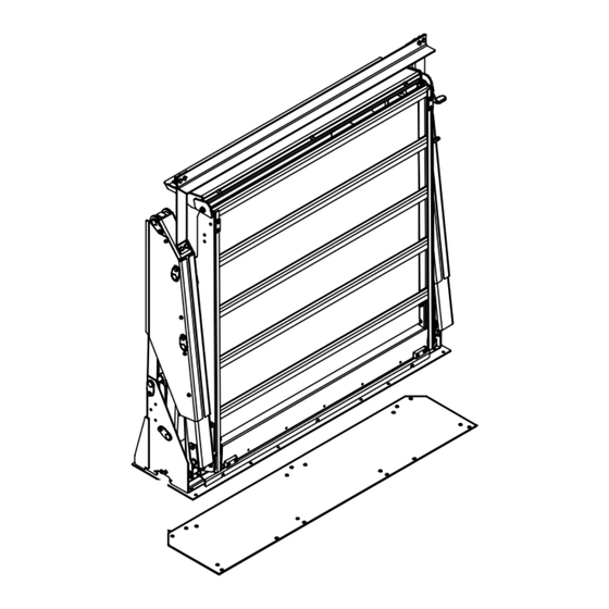
2. Verify mounting kit, liftgate, and other components (Figure 1 and Table 1).
LIFTGATE
DRILL
TEMPLATE
(UNDER LIFTGATE)
3. Remove the pump box cover by removing five (5) screws (Figure 3) .
4. Unscrew the solid plastic plug from the pump reservoir and Install the vent plug provided,
if not already installed (Figure 2).
5. Replace the pump box cover and screws.
6. Remove and Save the six (6) screws fastening the base plate cover to the base plate (Figure 3).
7. Remove and Sav e base plate cover (Figure 3).
With the screws removed, it can slide out from under the platform.
8. Remove and Save the floor transition that is under the base plate cover.
Platform
Base Plate
Cover Screw
DPN: 095260
BRACKET KIT
Figure 1: Part identification.
Lift Angle
(2) Pump Box
Cover Screw
Base Plate Cover
Figure 3: Base plate cover and pump box.
Page 1 of 14
Table 1: Parts list.
QTY.
PART NO.
1
CVT56
Liftgate
1
015241
Drill Template
1
015323
Bracket Kit
(3) Pump Box
Cover Screw
Floor Transition
(under base plate cover)
DESCRIPTION
OWNER'S / OPERATOR'S
MANUAL
V2 Series
1100 LB Capacity
TOMMY GATE
Vent plug
Figure 2: Vent plug.
Lift Angle
Rev 1
8-24-18
Advertisement

Related Manuals for Tommy Gate V2 Series

Summary of Contents for Tommy Gate V2 Series
- Page 1 V2 Series Mounting Instructions Sprinter 2500, 170 WB, NON-Extended Body 2007-present Preparing the Gate 1. Remove the bracket kit and pallet sides from the liftgate pallet. Table 1: Parts list. Part of the pallet side is bolted to the liftgate platform.
- Page 2 V2 Series Mounting Instructions Preparing the Gate (continued) Caution: Be careful not to tip the liftgate over during the next steps. The liftgate will stand upright, but could be knocked over with a moderate force. 9. Remove the screws and bolts fastening the liftgate to the pallet.
- Page 3 V2 Series Mounting Instructions Preparing the Van (continued) 13. Check for obstructions before drilling in the next steps. Note: Do not drill all holes in the template, they are not all used for this application. Only drill holes when indicated.
- Page 4 V2 Series Mounting Instructions Installing the Floor Supports 1. Position the 1/4" floor supports in the van (Figure 8). 2. Position a 1/4" spacer at each "C" location (Figure 8). These spacers are being added to the shims at this location.
- Page 5 V2 Series Mounting Instructions Installing the Liftgate Caution: Be careful not to tip the liftgate over during the next steps. The liftgate will stand upright, but could be knocked over with a moderate force. 1. Lift the liftgate by the lifting angle with a fork truck (Figure 10).
- Page 6 V2 Series Mounting Instructions Installing the Liftgate (continued) 5. Install a square washer, 3/8" flat washer, lock washer, and hex nut on each of the "C" and "D" location bolts (Figure 11). Do not tighten at this time. 6. Install a square washer, 3/8" flat washer, lock washer, and hex nut on the "A" location bolt (Figure 11).
- Page 7 V2 Series Mounting Instructions Installing the Liftgate (continued) 8. Install an "A" bracket onto the "B" and "F" location bolt s (Figure 12). Be aware that there is a left and right of these brackets. 9. Install a "B" bracket onto the "B" and "F" location bolt s (Figure 12). Be aware that there is a left and right of these brackets.
- Page 8 4. Drill a 7/8" hole in the rear of the battery box, avoiding the battery, to run the power cables through. Note: Follow the Tommy Gate Recommended Electrical Wiring Guidelines and wiring diagram (Figure 16) in the following steps. 5. Route the power cables under the vehicle from the liftgate, along the frame, to a location near the foot well (Figure 14).
- Page 9 Routing the Power Cables (continued) 12. Install the copper lugs and heat shrink tubing on all required ends. 13. Connect the circuit breaker and battery as outlined in the Tommy Gate Recommended Electrical Wiring Guidelines and wiring diagram (Figure 16).
-
Page 10: Electrical Wiring Diagram
V2 Series Mounting Instructions ELECTRICAL WIRING DIAGRAM The original TOMMY GATE hydraulic lift Pendant Control NOTE !!! IF GATES ARE NOT WIRED PLEASE READ AND FOLLOW ALL IN ACCORDANCE WITH THIS DIAGRAM DIRECTIONS BEFORE PROCEEDING YOUR WARRANTY WILL BE VOID. - Page 11 V2 Series Mounting Instructions Finishing the Liftgate Installation 1. Install the "Do's and Do Not's" decal in a highly visible area in the vehicle cab. This decal is with the Owner's / Operator's Manual. 2. Verify that all mounting bolts and nuts have been installed and tightened.
- Page 12 V2 Series Mounting Instructions Adjusting the Platform to Stop at Bed Height 1. Lower the platform below bed height. 2. Raise the platform as high as it will go with just the pendant toggle. 5/16" Nut 3. Check if the platform loading surface is even with base plate cover (Figure bb).
- Page 13 Painting the Liftgate (if needed) Your Tommy Gate has been primed with a gray polyurethane and painted with a black semi-gloss polyurethane topcoat to protect it from the environment. No additional paint is required unless shipping or installation damage or outdoor storage exposure has deteriorated the Tommy Gate paint.
- Page 14 (2) Battery power for your Tommy Gate should come directly from the battery or approved connection point through the supplied circuit breaker or fuse. The circuit breaker or fuse should be installed as close to the battery as possible.
Need help?
Do you have a question about the V2 Series and is the answer not in the manual?
Questions and answers