
Related Manuals for Polaris DP-20


Summary of Contents for Polaris DP-20
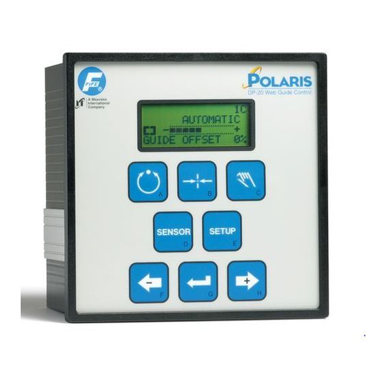
- Page 1 POLARIS DP-20 WEB GUIDE CONTROLLER User Manual AUTOMATIC × -ãããããÜÜÜÜÜ+ 06-05-2007 Figure Sheet 1-862-D © 2007 Fife Corporation. All rights reserved.
- Page 2 THIS PAGE INTENTIONALY LEFT BLANK 06-05-2007 DP-20 WEB GUIDE CONTROLLER Figure Sheet 1-862-D...
- Page 3 DP-20 WEB GUIDE CONTROLLER USER MANUAL COPYRIGHT COPYRIGHT All rights reserved. Any reproduction of this User Manual, in any form, in whole or in part, requires the prior written consent of Fife Corporation. The information given in this User Manual is subject to change without notice.
- Page 4 THIS PAGE INTENTIONALY LEFT BLANK 06-05-2007 DP-20 WEB GUIDE CONTROLLER Figure Sheet 1-862-D...
-
Page 5: Table Of Contents
DP-20 WEB GUIDE CONTROLLER USER MANUAL TABLE OF CONTENTS GENERAL INTRODUCTION DP-20 General Information ....................1-1 OPERATOR INTERFACE Function of the Operator Level Keys................2-1 Features of the LCD Panel.....................2-2 SETUP MENU STRUCTURE Setup Menu Notes ......................3-1 Setup Menu Chart ......................3-2 SYSTEM SETUP MENUS AVAILABLE FROM AUTOMATIC MODE 1X.1, System Gain ......................4-1... - Page 6 DP-20 WEB GUIDE CONTROLLER USER MANUAL 3X.2.6, Set Jog Speed ...................6-18 3X.2.7, Set Sensor Type ..................6-19 Advanced Menus ......................6-20 3X.3.1, Restore Settings ..................6-20 3X.3.2, Backup Settings ..................6-20 3X.3.3, Set Password, Enter Password ..............6-21 3X.3.3, Set Password, Delete Password..............6-22 3X.3.3, Set Password, Change Password .............6-23 3X.3.4, Set Output A Delay ..................6-24...
-
Page 7: General Introduction
Guide or Edge Guiding from either edge. Edge of Line or Center of Line Guiding is also supported. The DP-20 can be either panel mounted or wall mounted (with optional mounting bracket). The DP-20 Web Guide Controller is designed to control one motor, up to and including a 1.3 Amp motor, provided by Fife Corporation. 06-05-2007... - Page 8 THIS PAGE INTENTIONALY LEFT BLANK 06-05-2007 DP-20 WEB GUIDE CONTROLLER Figure Sheet 1-862-D...
-
Page 9: Operator Interface
DP-20 WEB GUIDE CONTROLLER USER MANUAL OPERATOR INTERFACE Function of the Operator Level Keys AUTOMATIC This key initiates the Automatic mode. Correction is applied to the web by moving the guide in response to the output of the sensor(s) that has been selected. -
Page 10: Features Of The Lcd Panel
While in any of the setup menus, a flashing dot (see arrow) in SETUP (SC) this line indicates that a timer is running. The DP-20 is waiting for a ~ƒ GAIN response from the operator. If no response is detected in 3 minutes, the ãÜÜÜÜÜÜÜÜÜ... - Page 11 DP-20 WEB GUIDE CONTROLLER USER MANUAL LINE 2 While at the Operator Level, this line contains the name of AUTOMATIC the currently selected Operation mode. × -ãããããÜÜÜÜÜ+ LINE 2 While in the setup menus, this line indicates that a Setup ×...
- Page 12 DP-20 WEB GUIDE CONTROLLER USER MANUAL LINE 4 While in the Setup Menus, this line indicates the value × 3A.2.2 SETUP (MAN) associated with the menu as defined in Line 3. If it is possible to modify GUIDE POINT the value, it will be flashing.
-
Page 13: Setup Menu Structure
DP-20 WEB GUIDE CONTROLLER USER MANUAL SETUP MENU STRUCTURE Setup Menu Notes 1. The SETUP key is used to enter the Setup Menus. 2. The ENTER key is used to store changes in the Setup Menus. 3. Pressing the MANUAL key in most Setup Menus will exit the Setup Menus and return to the Operator Level. -
Page 14: Setup Menu Chart
DP-20 WEB GUIDE CONTROLLER USER MANUAL Setup Menu Chart AUTOMATIC MODE 1X.1 1X.2 1X.3 1X.4 Gain Guide Point Measurement Exit Menus SERVO-CENTER MODE 2X.1 2X.2 2X.3 2X.4 Servo-Center Servo-Center Measurement Exit Menus Gain Guide Point MANUAL MODE SELECT MENU 3X.1 3X.2... -
Page 15: 1, System Gain
DP-20 WEB GUIDE CONTROLLER USER MANUAL SYSTEM SETUP MENUS AVAILABLE FROM AUTOMATIC MODE 1X.1, System Gain 1. Press the SETUP key to enter the Setup ×Ø 1C.1 Menus. The GAIN menu will be displayed on SETUP (AUTO) GAIN the LCD Panel. -
Page 16: 3, Measurement
DP-20 WEB GUIDE CONTROLLER USER MANUAL 3. Press the ENTER key to allow adjustment of ×Ø 1C.2.1 SETUP (AUTO) the System Guide Point. The current Guide GUIDE POINT Point value will begin flashing on line 4. -ÜÜÜåÜÜÜ+ 0.0% 4. Use the ARROW keys to adjust the System ×Ø... - Page 17 DP-20 WEB GUIDE CONTROLLER USER MANUAL 3. Press the ENTER key to view the Measurement ×Ø 1C.3.1 menus. The level of the guiding signal from the MEASUREMENT × SENSOR (X5) Left Edge Sensor (Line Center if a line sensor -ããããÜÜÜÜ+ is being used) is displayed on Line 4.
- Page 18 DP-20 WEB GUIDE CONTROLLER USER MANUAL 10. Use the ARROW keys to scroll to the desired ×Ø 1C.3.8 Measurement menu. Next in the list is the MEASUREMENT SERIAL NUMBER SERIAL NUMBER. The serial number of the SN:10000 DP-20 is displayed on Line 4.
-
Page 19: 1, Servo-Center Gain
DP-20 WEB GUIDE CONTROLLER USER MANUAL SYSTEM SETUP MENUS AVAILABLE FROM SERVO-CENTER MODE 2X.1, Servo-Center Gain 1. Press the SETUP key to enter the Setup × 2A.1 SETUP (SC) Menus. The Servo-Center ( ) GAIN menu will ~ƒ ~ƒ GAIN be displayed on the LCD Panel. -
Page 20: 3, Measurement
DP-20 WEB GUIDE CONTROLLER USER MANUAL 4. Use the ARROW keys to adjust the SC Guide ×Ø 2C.2.1 Point to the desired position as indicated on SETUP (SC) ~ƒ GUIDE POINT line 4. -ÜÜåÜÜÜÜ+ -21.0% 5. If desired, press both of the ARROW keys ×Ø... - Page 21 DP-20 WEB GUIDE CONTROLLER USER MANUAL 5. Use the ARROW keys to scroll to the desired ×Ø 2C.3.3 MEASUREMENT Measurement menu. Next in the list is the ~ƒ SENSOR (X2) Servo-Center Sensor. The sensor signal is -ããããÜÜÜÜ+ displayed on Line 4.
- Page 22 THIS PAGE INTENTIONALY LEFT BLANK 06-05-2007 DP-20 WEB GUIDE CONTROLLER Figure Sheet 1-862-D...
-
Page 23: Basic Menus
DP-20 WEB GUIDE CONTROLLER USER MANUAL SYSTEM SETUP MENUS AVAILABLE FROM MANUAL MODE Basic Menus 3X.1.1, System Gain 1. Press the SETUP key to enter the Setup ×Ø 3C.1 SETUP (MAN) Menus. The SELECT MENU screen will be SELECT MENU displayed on the LCD Panel. -
Page 24: 1.3, Guide Polarity
DP-20 WEB GUIDE CONTROLLER USER MANUAL 3. Use the ARROW keys to scroll until GUIDE ×Ø 3C.1.2 SETUP (MAN) POINT is displayed on line 3. GUIDE POINT -ÜÜÜåÜÜÜ+ 0.0% 4. Press the ENTER key to allow adjustment of ×Ø 3C.1.2.1 SETUP (MAN) the System Guide Point. -
Page 25: 1.4, Calibration, Edge Sensors
DP-20 WEB GUIDE CONTROLLER USER MANUAL 5. Press the ENTER key to allow adjustment of × 3A.1.3.1 SETUP (MAN) the Guide Polarity. The current Guide Polarity GUIDE POLARITY setting will begin flashing on line 4. 6. Use ARROW keys change ×... -
Page 26: 1.4, Calibration, Line Sensor, Center Of Line Guiding
DP-20 WEB GUIDE CONTROLLER USER MANUAL 7. Press the ENTER key. WAIT... will be displayed Ø 3B.1.4.2 UNCOVER SENSOR for a few seconds on line 4 of the LCD Panel. -ÜÜÜÜÜÜÜÜÜÜ+ Maintain the web position during this wait WAIT... period. -
Page 27: 1.4, Calibration, Line Sensor, Edge Of Line Guiding
DP-20 WEB GUIDE CONTROLLER USER MANUAL 5. If necessary, use the ARROW keys to select ý 3D.1.4.1 SETUP (MAN) the Center of Line sensor input. will be ý SELECT SENSOR displayed on line 1. (X4) 6. Press the ENTER key to begin the calibration. - Page 28 DP-20 WEB GUIDE CONTROLLER USER MANUAL 2. Press the ENTER key to enter the BASIC Ł 3E.1.1 SETUP (MAN) Menus. The GAIN menu will be displayed. GAIN ãÜÜÜÜÜÜÜÜÜ 10.0% 3. Use ARROW keys scroll until Ł 3E.1.4 SETUP (MAN) CALIBRATION is displayed on line 3.
-
Page 29: 1.4, Calibration, Servo-Center Sensor
DP-20 WEB GUIDE CONTROLLER USER MANUAL 10. If the contrast is not sufficient for guiding, Ł 3E.1.4.6 FAILED will be displayed on line 2. Press the FAILED -áÜÜÜÜÜÜÜÜÜ+ MANUAL key to exit the setup menus and return to the Operator Level. Repeat this procedure, as necessary. -
Page 30: 1.5, Auto Setup
DP-20 WEB GUIDE CONTROLLER USER MANUAL 8. Press the ENTER key. If the contrast is ~ƒ 3F.1.4.4 SUCCESSFUL sufficient, SUCCESSFUL will be displayed for a -ãããããããããá+ 95% few seconds on line 2, then the unit will automatically exit the menus and return to the Operator Level. -
Page 31: 1.6, Servo-Center Gain
DP-20 WEB GUIDE CONTROLLER USER MANUAL 6. Press the ENTER key to begin the Auto Setup. Ø 3B.1.5.3 POSITION WEB IN If the web is not positioned near the center of CENTER OF SENSOR the sensor field of view, the LCD Panel will -ãããããÜÜÜÜÜ+... -
Page 32: 1.7, Servo-Center Polarity
DP-20 WEB GUIDE CONTROLLER USER MANUAL 6-10 5. Use the ARROW keys to adjust the Gain value × 3A.1.6.1 SETUP (SC) to the desired level as indicated on line 4. If an ~ƒ GAIN ARROW key is held down, the speed of the ããÜÜÜÜÜÜÜÜ... -
Page 33: 1.8, Measurement
DP-20 WEB GUIDE CONTROLLER USER MANUAL 6-11 3X.1.8, Measurement 1. Press the SETUP key to enter the Setup ×Ø 3C.1 SETUP (MAN) Menus. The SELECT MENU screen will be SELECT MENU displayed on the LCD Panel. BASIC 2. Press the ENTER key to enter the BASIC ×Ø... -
Page 34: Special Menus
DP-20 WEB GUIDE CONTROLLER USER MANUAL 6-12 9. Use the ARROW keys to scroll to the desired ×Ø 3C.1.8.6 MEASUREMENT Measurement menu. Next in the list is the DIGITAL INPUTS DIGITAL INPUTS. The status of the inputs is 000000 displayed on Line 4. The order in which the inputs are displayed is 5,4,3,2,1,0. -
Page 35: 2.2, Set Operation Mode Enable
DP-20 WEB GUIDE CONTROLLER USER MANUAL 6-13 4. If necessary, press the SENSOR key to select × 3A.2.1 SETUP (MAN) the desired sensor mode as indicated on line 1. DEADBAND -ÜÜÜÜÜÜÜ+ 0.0% 5. Press the ENTER key to enter the DEADBAND ×... -
Page 36: 2.3, Set Sensor Mode Enable, Edge Sensors
DP-20 WEB GUIDE CONTROLLER USER MANUAL 6-14 6. Use the ARROW keys to scroll to the desired × 3A.2.2.2 selection as indicated on line 4 of the LCD SETUP (MAN) |AUTO|SC |MAN | Panel. YES indicates that the corresponding |YES |YES | operation mode is enabled. -
Page 37: 2.3, Set Sensor Mode Enable, Line Sensor
DP-20 WEB GUIDE CONTROLLER USER MANUAL 6-15 6. Use the ARROW keys to scroll to the desired × 3A.2.3.2 SETUP (MAN) selection, as indicated on line 4 of the LCD | × | Ø | ×Ø | Panel. YES indicates that the corresponding |YES |YES |NO sensor mode is enabled. -
Page 38: 2.4, Set Jog Enable
DP-20 WEB GUIDE CONTROLLER USER MANUAL 6-16 4. Use the ARROW keys to scroll until SENSOR ý 3D.2.3 SETUP (MAN) ENABLE is displayed on line 3. The current SENSOR ENABLE selection is displayed on Line 4. | ý | Ł... -
Page 39: 2.5, Set Jog Polarity
DP-20 WEB GUIDE CONTROLLER USER MANUAL 6-17 6. Use the ARROW keys to scroll to the desired × 3A.2.4.2 SETUP (MAN) selection, as indicated on line 4 of the LCD |AUTO|SC |MAN | Panel. YES indicates that the jog is enabled in... -
Page 40: 2.6, Set Jog Speed
DP-20 WEB GUIDE CONTROLLER USER MANUAL 6-18 4. Use the ARROW keys to scroll until SET JOG × 3A.2.5 SETUP (MAN) POLARITY is displayed on line 3. The current SET JOG POLARITY setting will be displayed on Line 4. 5. Press the ENTER key to enter the Set Jog ×... -
Page 41: 2.7, Set Sensor Type
DP-20 WEB GUIDE CONTROLLER USER MANUAL 6-19 7. Press the ENTER key to store the change or MANUAL press the MANUAL key to abort the procedure. × -ãããããáÜÜÜÜ+ The system will exit the setup menus, and return to the Operator Level. -
Page 42: Advanced Menus
DP-20 WEB GUIDE CONTROLLER USER MANUAL 6-20 Advanced Menus 3X.3.1, Restore Settings 1. Press the SETUP key to enter the Setup × 3A.1 SETUP (MAN) Menus. The SELECT MENU screen will be SELECT MENU displayed on the LCD Panel. BASIC 2. -
Page 43: 3.3, Set Password, Enter Password
DP-20 WEB GUIDE CONTROLLER USER MANUAL 6-21 3. Press the ENTER key to enter the Advanced × 3A.3.1 SETUP (MAN) Menus. The RESTORE SETTINGS menu will RESTORE SETTINGS be displayed. 4. Use the ARROW keys to scroll until BACKUP ×... -
Page 44: 3.3, Set Password, Delete Password
DP-20 WEB GUIDE CONTROLLER USER MANUAL 6-22 6. Using the proper keys, enter the desired × 3A.3.3.2 SETUP (MAN) password. The password can be 1 to 6 keys in ENTER PASSWORD length. Each key press is indicated by an “*“ on ****** Line 4. -
Page 45: 3.3, Set Password, Change Password
DP-20 WEB GUIDE CONTROLLER USER MANUAL 6-23 6. Using the proper keys, enter the current × X3A.3.3 SETUP (MAN) password. Each key press is indicated by an “*“ ENTER PASSWORD on Line 4. ****** 7. Press the ENTER key to accept the password. -
Page 46: 3.4, Set Output A Delay
DP-20 WEB GUIDE CONTROLLER USER MANUAL 6-24 6. Using the proper keys, enter the current × X3A.3.3 SETUP (MAN) password. Each key press is indicated by an ENTER PASSWORD “*“ on Line 4. ****** 7. Press the ENTER key to accept the password. -
Page 47: 3.5, Set Output B Delay
DP-20 WEB GUIDE CONTROLLER USER MANUAL 6-25 3. Press the ENTER key to enter the Advanced × 3A.3.1 SETUP (MAN) Menus. The RESTORE SETTINGS menu will RESTORE SETTINGS be displayed. 4. Use the ARROW keys to scroll until SET ×... -
Page 48: 3.6, Set Loss Of Null Output Range
DP-20 WEB GUIDE CONTROLLER USER MANUAL 6-26 5. Press the ENTER key to enter the SET × 3A.3.5.1 SETUP (MAN) OUTPUT DELAY menu. The current delay time SET OUTPUT DELAY will begin flashing. OUTPUT B: 0.00s 6. Use the ARROW keys to adjust the delay time ×... -
Page 49: 3.7, Digital I/O, Enable/Disable
DP-20 WEB GUIDE CONTROLLER USER MANUAL 6-27 7. Press the ENTER key to store the change or MANUAL press the MANUAL key to abort the procedure. × -ãããããáÜÜÜÜ+ The system will exit the setup menus, and return to the Operator Level. -
Page 50: 3.8.2, Test Signals, Toggle Outputs
DP-20 WEB GUIDE CONTROLLER USER MANUAL 6-28 2. Use ARROW keys scroll until × 3A.3 SETUP (MAN) ADVANCED is displayed on line 3. SELECT MENU ADVANCED 3. Press the ENTER key to enter the Advanced × 3A.3.1 SETUP (MAN) Menus. The RESTORE SETTINGS menu will RESTORE SETTINGS be displayed. -
Page 51: 3.8.3, Test Signals, Guide Test Mode
DP-20 WEB GUIDE CONTROLLER USER MANUAL 6-29 3. Press the ENTER key to enter the Advanced × 3A.3.1 SETUP (MAN) Menus. The RESTORE SETTINGS menu will RESTORE SETTINGS be displayed. 4. Use the ARROW keys to scroll until TEST ×... - Page 52 DP-20 WEB GUIDE CONTROLLER USER MANUAL 6-30 4. Use the ARROW keys to scroll until TEST × 3A.3.8 SETUP (MAN) SIGNALS is displayed on line 3. TEST SIGNALS 5. Press the ENTER key to enter the TEST × 3A.3.8.1 SETUP (MAN) SIGNALS menu.
-
Page 53: Language Menu
DP-20 WEB GUIDE CONTROLLER USER MANUAL 6-31 9. Use the ARROW keys to modify the oscillation × 3A.3.8.3.1 RUNNING speed, as displayed on line 4. The left × MODE1 ARROW key decreases the time per direction -ÜÜÜÜÜÜÜÜ+ 0.50s change (increases speed). The right ARROW key increases the time per direction change (decreases speed). -
Page 54: Custom Menus
DP-20 WEB GUIDE CONTROLLER USER MANUAL 6-32 4. Use the ARROW keys to scroll until the desired Ø 3B.4.2 SETUP (MAN) language is displayed. SPRACHE WAEHLEN DEUTSCH 5. Press the ENTER key to store the change or MANUELL press the MANUAL key to abort the procedure. -
Page 55: 5.2, Set Asc Limits
DP-20 WEB GUIDE CONTROLLER USER MANUAL 6-33 3X.5.2, Set ASC Limits This procedure is used to set the ASC Limits. These limits are configurable for each sensor mode. Use the “ASC CONTROL“ menu to enable the ASC function. 1. Press the SETUP key to enter the Setup ×... -
Page 56: 5.3, Set Asc Source
DP-20 WEB GUIDE CONTROLLER USER MANUAL 6-34 10. Press the ENTER key to store the new ASC MANUAL LIMITS, or press the MANUAL key to abort the Ø -ãããããáÜÜÜÜ+ changes. The system will exit the setup menus, and return to the Operator Level. -
Page 57: Parallel Matrix
DP-20 WEB GUIDE CONTROLLER USER MANUAL PARALLEL MATRIX Parallel Input Matrix INPUTS MODE EXTERNAL LOCK AUTOMATIC MANUAL SERVO-CENTER JOG LEFT * JOG RIGHT * RGPC LEFT * RGPC RIGHT * RGPC RESET * SENSOR, EDGE L OR LINE CENTER **... - Page 58 THIS PAGE INTENTIONALY LEFT BLANK 06-05-2007 DP-20 WEB GUIDE CONTROLLER Figure Sheet 1-862-D...
-
Page 59: System Notes
DP-20 WEB GUIDE CONTROLLER USER MANUAL SYSTEM NOTES 1. Disconnect power from the DP-20 before connecting or disconnecting any cables. 2. All cable connectors must be tightened sufficiently to provide the required connection for the cable shielding. 3. Sensor selection changes are allowed in Manual and Servo-Center modes, only. - Page 60 THIS PAGE INTENTIONALY LEFT BLANK 06-05-2007 DP-20 WEB GUIDE CONTROLLER Figure Sheet 1-862-D...
-
Page 61: Troubleshooting
DP-20 WEB GUIDE CONTROLLER USER MANUAL TROUBLESHOOTING Fault Diagnostics – Fault Rectification An incorrect setting on the DP-20 is often the cause of incorrect or undesirable guiding characteristics. Faults and the procedures for rectifying the faults are described below. Fault Description... -
Page 62: Fault Codes
DP-20 WEB GUIDE CONTROLLER USER MANUAL Fault Codes When a fault is indicated on the LCD Panel, the Menu Number on line 1 of the LCD Panel is re- defined as follows; XX.X.X.X MENU NUMBER OPERATION MODE SENSOR MODE __.0 FAULT INDICATION __._.XXX... -
Page 63: Return Shipment Instructions
Return Shipment Instructions If it is necessary to return the Polaris DP-20 to Fife Corporation for service, care must be taken to properly package the unit to prevent damage during shipment. Pay particular attention to the power receptacle on the rear panel of the unit. -
Page 64: Motor/Valve List
DP-20 WEB GUIDE CONTROLLER USER MANUAL Motor/Valve List LCD Indication Current Motor/Valve Resistor Typical Assembly 0.6A –TACH 2.05K 0.6 A 92308-001 Motor, Tachless 2.05K Tachless Symat 25 1.3A –TACH 3.48K 1.3 A 92309-001 Motor, Tachless 3.48K Tachless Symat 50 0.6A MOTOR 6.81K 0.6 A... -
Page 65: Specifications
DP-20 WEB GUIDE CONTROLLER USER MANUAL 10-1 SPECIFICATIONS General Universal Input Line - 100 VAC -10% to Voltage Range 240 VAC +10% Input Line Frequency - 47-63 Hz Power consumption - 130 VA Internal Fuse - 3.15 A (not user serviceable) Operating Ambient - 0°... -
Page 66: Certifications And Compatibility With Industrial Environments
DP-20 WEB GUIDE CONTROLLER USER MANUAL 10-2 Certifications and Compatibility with Industrial Environments Product Certification - UL / cUL / CE Protection Class - IP 54 Maximum Cable Lengths Sensors (Except SE-26A) - 50 m (165 ft) SE-26A Sensor - 25 m (82 ft)