Table of Contents
Advertisement
Quick Links
No: 24614 – 07/18 rev. 2
Catalog Numbers • Les Numéros de Catalogue • Números de Catálogo: LMLS-500/LMLS-500-L
Country of Origin: Made in China • Pays d'origine: Fabriqué en Chine • País de origen: Hecho en China
Models ending in -U are BAA and TAA compliant (Product produced in the U.S.)
UNIT DESCRIPTION
The LMLS-500 is an open loop photosensor that measures
daylight in order to automatically switch or dim up to three zones
of lighting. It is part of a Digital Lighting Management (DLM)
system and sends light level signals to control loads connected
to DLM switching or dimming room controllers. The LMLS-500
has a photodiode with an extended range of 1-6,553 footcandles
(fc) and photopic correction to mimic the human eye for precise
measurement of visible light.
The LMLS-500 operates on Class 2 power supplied to a DLM
local network by one or more DLM room controllers. Once set
up, the LMLS-500 uses switching or dimming setpoints and other
control parameters to manage the light levels throughout the day
regardless of changing daylight contribution.
Sensor Installation and Configuration Overview
1. Mount the photosensor so that the Daylight Viewing Port
directly views the daylight entering the space through
a window or a skylight. See Placement Guidelines and
Mounting the Photosensor.
2. Complete all wiring and turn ON power to the room
controller.
3. Use the LMCS-100 or LMCT-100 configuration tool to
complete the configuration process. The LMLS-500 will not
operate properly until the configuration and calibration is
successful.
a. Select the LMLS-500 to configure and select Zone
Setup.
b. Choose the desired number of zones (1-3), then select
the operating mode for each zone (Switched, Bi-Level,
Tri-Level, Dimmed).
c. Assign individual loads to each of the configured zones.
d. Calibrate the LMLS-500. Use a light meter to measure
the light level at each zone with the lights ON and OFF to
determine the relationship between the light level at the
task and light level at the LMLS-500.
e. Adjust Zone Settings and Advanced Settings to meet
specific sequence of operation requirements.
f. Use Test Mode to verify the LMLS-500 operation.
Wattstopper
Digital Lighting Management Open Loop Multiple Zone Photosensor
Installation Instructions • Instructions d'Installation • Instrucciones de Instalación
SPECIFICATIONS
Light sensor range ................................................... 1 to 6,553 fc
Voltage .............................................................................24VDC
Current Consumption .............................max 13mA, typical 3mA
Power Supply .............................. Wattstopper Room Controllers
Connection to the DLM Local Network ......................1 RJ45 port
Environment:
Operating Temperature ......................32° to 131°F (0° to 55°C)
Storage Temperature ....................... 23° to 140°F (-5° to 60°C)
Relative Humidity ........................... 5 to 95% (non condensing)
Other:
RoHS compliant, 5-year warranty
Dimensions:
LMLS-500/500-L
Length ................................................................3.9" (99mm)
Width .................................................................1.2" (30mm)
Depth ................................................. Minimum 1.0" (25mm)
.......................................................... Maximum 1.5" (38mm)
Tube Diameter ........................................................0.88" (22mm)
Ceiling Tile Thickness:
LMLS-500 .........................................................0"- 5/8" (16mm)
LMLS-500-L .................................. 5/8" (16mm) - 1.25" (31mm)
Factory Defaults
Switching Operation:
ON Setpoint* ......................................................................35 fc
OFF Setpoint* ....................................................................53 fc
ON Time Delay ................................................................20 sec
OFF Time Delay ..............................................................10 min
Dimming Operation:
Setpoint* .............................................................................50 fc
Ramp Rate Up .......................................................20% per sec
Ramp Rate Down .....................................................2% per sec
Cut Off Delay ....................................................................Never
Advanced Parameters:
Allow Override ....................................................................... No
Override Time.................................................................. Infinity
Hold Off .................................................................................No
Scenes Stop Daylighting ....................................................... No
Ignore After Hours ................................................................. No
* Setpoints change automatically upon calibration
®
Advertisement
Table of Contents

Related Manuals for LEGRAND Wattstopper LMLS-500


Summary of Contents for LEGRAND Wattstopper LMLS-500
-
Page 1: Specifications
Wattstopper ® Digital Lighting Management Open Loop Multiple Zone Photosensor No: 24614 – 07/18 rev. 2 Installation Instructions • Instructions d’Installation • Instrucciones de Instalación Catalog Numbers • Les Numéros de Catalogue • Números de Catálogo: LMLS-500/LMLS-500-L Country of Origin: Made in China • Pays d’origine: Fabriqué en Chine • País de origen: Hecho en China Models ending in -U are BAA and TAA compliant (Product produced in the U.S.) SPECIFICATIONS Light sensor range ........... -
Page 2: Placement Guidelines
PLACEMENT GUIDELINES WARNING: DO NOT USE THE DLM LOCAL NETWORK TO CONTROL LOADS OTHER THAN LIGHTING IF THE LOAD IS NOT IN VIEW OF A PERSON AT ALL CONTROL LOCATIONS. DO NOT USE DLM TO CONTROL ANY LOAD THAT MIGHT BE DANGEROUS OR CAUSE A HAZARDOUS SITUATION IF ACCIDENTALLY ACTIVATED. The LMLS-500 switches or dims electric light in response to daylight. -
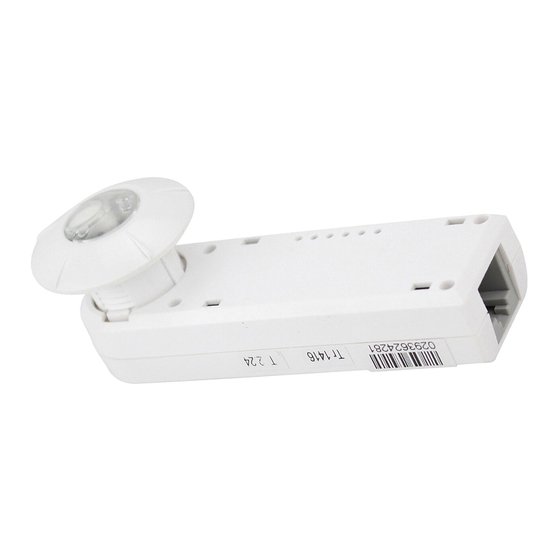
Page 3: Mounting The Photosensor
MOUNTING THE PHOTOSENSOR In most applications, the unit is mounted through a ceiling tile, with only the lens being visible from inside the room; the remainder of the unit rests on top of the tile. It can also be mounted on or through the wall of a skylight light well. In these types of applications, an accessory plastic mounting bracket is required. -
Page 4: Wiring Directions
WIRING DIRECTIONS OPERATION Installation shall be in accordance with all applicable regulations, The LMLS-500 communicates to all other Lighting Management wiring practices, and codes. devices connected to the DLM Local Network. It is dependent on a DLM Room Controller (LMRC-100 series for ON/OFF switched The DLM Local Network is free topology low voltage wiring. -
Page 5: Operating Modes
OPERATING MODES Plug n’ Go The LMLS-500, unlike most other DLM Components, will not auto-configure. The LMLS-500 must be manually configured using the LMCT-100 or LMCS-100. Push n’ Learn Push and Learn™ (PnL) provides for remote load binding and configuration within the room, without requiring direct access to the Room Controller(s). - Page 6 CONFIGURATION The configuration process establishes the appropriate parameters for operation. This is done through the use of an LMCT-100 configuration tool. If no configuration steps are taken, the sensor will use its default values for setpoints. The LMCT-100 Wireless IR Configuration Tool is a handheld tool for setup and testing of Wattstopper Digital Lighting Management (DLM) devices.
-
Page 7: Zone Setup
SPECIFIC PHOTOSENSOR SEARCH PHOTOSENSOR The Search Photosensor function allows you to identify which D a y l i g h t i n g L M L S - 5 0 0 LMLS-500 will be commissioned. After enabling and pointing the P o i n t t o t h e d e s i r e d LMCT-100 at any DLM device, a list of all LMLS-500s in the DLM S p e c i fi... - Page 8 ZONE SETUP (CONTINUED) Next Tri-Level To continue to assign Daylight Load binding to load 2, choose Tri-level mode provides four light levels within the daylighting zone NEXT. controlled by the photosensor by using 2 load circuits. Load 1 - OFF Z o n e S e t u p L M L S - 5 0 0 Off = 0%...
- Page 9 Bi-Level Sequence of Operation (per zone)* Off/Med/Max When the ambient light level reaches the OFF Setpoint again, the Med & Max assigned load turns OFF. Load 1 - Med & Max Ambient Light Load 2 - Max When the ambient light level reaches the ON Setpoint, the Med &...
- Page 10 CALIBRATION Calibration allows you to establish a relationship between the workplane illuminance and the measured daylight at the photocell. Use the LMCT-100 for the Calibration process. 1. Complete all wiring and turn power ON to the connected room controllers. 2. Select the LMLS-500 to be calibrated using the LMCT-100. 3.
-
Page 11: Zone Settings
ZONE SETTINGS Zone Settings allows you to modify Send L M L S - 5 0 0 0 2 9 3 7 2 4 9 0 9 the photosensor Daylighting D a y l i g h t i n g L M L S - 5 0 0 Setpoints, Time Delays and Ramp Z o n e S e t u p... -
Page 12: Advanced Settings
If Hold Off = <Yes>, the sensor will limit the loads to the level ZONE SETTINGS (CONTINUED) presently allowed by daylight contribution. This means that the loads may not initially turn ON (if the ambient light level is high Send - above the ON or Dimming Setpoint), but will become active D a y l i g h t i n g L M L S - 5 0 0... -
Page 13: Control Mode
CONTROL MODE Control Mode allows you to select the control status of the Demo: photosensor. After choosing Control Mode and pressing Select, Demo mode will allow the photosensor to select a set of point to the LMLS-500 and press Select. The current control mode preset parameters. -
Page 14: Troubleshooting
TROUBLESHOOTING Lights do not switch or dim when desired, under daylight control • Use the pushbutton on the photosensor face to manually test load control (see SENSOR PUSHBUTTONS on page 3). If the lights do not switch ON and OFF, check Zone Settings to rebind the loads. If the lights do switch ON and OFF, use the Zone Settings screen to verify that the ON and OFF setpoints are correct (if Switching / Bi-Level / Tri-Level), or if dimmed, dimming setpoint is correct. - Page 16 No. 24614 – 07/18 rev. 2 © Copyright 2018 Legrand All Rights Reserved. 800.879.8585 © Copyright 2018 Tous droits réservés Legrand. www.legrand.us/wattstopper © Copyright 2018 Legrand Todos los derechos reservados.
Need help?
Do you have a question about the Wattstopper LMLS-500 and is the answer not in the manual?
Questions and answers