
Summary of Contents for IAI IA-101-X-MW
- Page 1 PC Software for X-SEL IA-101-X-MW IA-101-X-MW-JS IA-101-XA-MW IA-101-X-USBS IA-101-X-USBMW IA-101-TT-USB 22th Edition Operation Manual IAI Corporation...
- Page 3 • Information contained in this operation manual is subject to change without notice for the purpose of product improvement. • If you have any question or comment regarding the content of this manual, please contact “IAI Customer Center Eight” or the IAI sales office near you.
-
Page 5: Table Of Contents
Table of Contents Support Models.........................1 Installing V6.0.0.0 Compatible with the IA Super SEL Controller E/G Types and the DS Controller ..........................2 Software License Agreement ....................5 A Word of Caution........................6 Safety Guide ..........................7 1. Before You Begin......................15 Items Supplied with This Software (Product Components)..............15 System Requirements..........................17 Installing the Software ..........................18 1.3.1... - Page 6 4. Program Edit Window.......................97 Explanation of the Items Displayed in the Program Edit Window............97 Saving a Program, Transferring and Closing the Edit Window............. 105 4.2.1 Saving a Program Online, Transferring and Closing the Edit Window .......... 105 4.2.2 Transferring a Program Created Offline..................108 Saving All Programs to a File .........................110 Running the Program ..........................113 Cycle Time Measurement ........................114...
- Page 7 11. Monitor ...........................199 12. RC Gateway Function Setting ..................223 13. How to Reset an Absolute Encoder ................224 13.1 Orthogonal Axis (Absolute Specification) (excluding XSEL-RA/SA, RAX/SAX) ........224 13.2 Orthogonal Axis (Battery-less Absolute Specification and XSEL-RA/SA, RAX/SAX) ......227 13.3 Scara Axis ............................. 230 13.3.1 Absolute Reset Preparation ......................
-
Page 9: Support Models
Support Models Various data file extensions Support Model Name Started Program Program Global Backup Version Position Parameter Symbol Coordinate (Individually) (Batch) data Data XSEL-J/K V1.0.0.0 XSEL-JX/KX V2.0.0.0 XSEL-P/Q x2pg x2pa x2pt x2pm x2sm x2gd x2bk V3.0.0.0 XSEL-P/Q (compatible with increased memory) x2pg2 x2pa2 x2pt2... -
Page 10: Installing V6.0.0.0 Compatible With The Ia Super Sel Controller E/G Types And The Ds Controller
Installing V6.0.0.0 Compatible with the IA Super SEL Controller E/G Types and the DS Controller V6.0.0.0 compatible with the IA Super SEL Controller E/G Types and the DS Controller is included in the CD-ROM and can be installed based on the following procedure. (Note) V6.0.0.0 runs with the following Windows operating systems. - Page 11 [4] Click TOOL. [5] The PC SOFT V6.0.0.0 folder containing the V6.0.0.0 installer will appear. Click PC SOFT V6.0.0.0 folder. [6] Click the ENGLISH folder.
- Page 12 [7] Double-click PC Interface Software…. The PC Interface Software for X-SEL installation screen will appear. Install the software based on the step [3] and thereafter described in 1.3.1 How to Install the PC Interface Software for X-SEL.
-
Page 13: Software License Agreement
Software. The User or a third party agrees not to claim compensation for damage from IAI for any loss suffered by the User or a third party as a result of installing and using the Licensed Software. -
Page 14: A Word Of Caution
A Word of Caution [1] This software is copyrighted by IAI Corporation (IAI). [2] The software and the manual can only be used under the terms and conditions of the license agreement. [3IAI cannot assume responsibility for any damage or loss resulting from the use of this software or the manual. -
Page 15: Safety Guide
Safety Guide Before using the product, ensure safety by following the safety precautions provided below and taking the necessary measures. Regulations and Standards Governing Industrial Robots Safety measures on mechanical devices are generally classified into four categories under the International Industrial Standard ISO/DIS 12100, “Safety of machinery,”... - Page 16 Requirements for Industrial Robots by Ordinance on Industrial Safety and Hygiene Drive-source Work area Work condition Measure Article cutoff Signs for starting operation Article 104 Outside the During automatic Not cut off Installation of railings, movement range operation Article 150-4 enclosure, etc.
- Page 17 Applicable Models of IAI’s Industrial Robots According to Notice of Ministry of Labor No. 51 and Labor Standards Bureau Director notice (No. 340), machines meeting the following conditions are not classified as industrial robots: (1) Single-axis robot with a motor wattage of 80 W or less...
- Page 18 Safety Precautions for Our Products The common safety precautions for the use of any of our robots in each operation. Precautions Work Description Model This product has not been planned and designed for the application where high level of Selection safety is required, so the guarantee of the protection of human life is impossible.
- Page 19 Precautions Work Description Installation and (1) Installation of Robot Main Body and Controller, etc. Start Make sure to securely hold and fix the product (including the work part). A fall, drop or abnormal motion of the product may cause a damage or injury. Also, be equipped for a fall-over or drop due to an act of God such as earthquake.
- Page 20 Work Description Precautions Installation and Take the measure so that the work part is not dropped in power failure or emergency stop. Start Wear protection gloves, goggle or safety shoes, as necessary, to secure safety. Do not insert a finger or object in the openings in the product. Failure to do so may cause an injury, electric shock, damage to the product or fire.
- Page 21 Precautions Work Description Maintenance and When the work is carried out with 2 or more persons, make it clear who is to be the leader Inspection and who to be the follower(s) and communicate well with each other to ensure the safety of the workers.
- Page 22 Caution Indications The safety precautions are divided into “Danger”, “Warning”, “Caution” and “Notice” according to the warning level, as follows, and described in the Instruction Manual for each model. Level Degree of Risk/Damage Symbol This indicates an imminently hazardous situation which, if the Danger Danger product is not handled correctly, will result in death or serious...
-
Page 23: Before You Begin
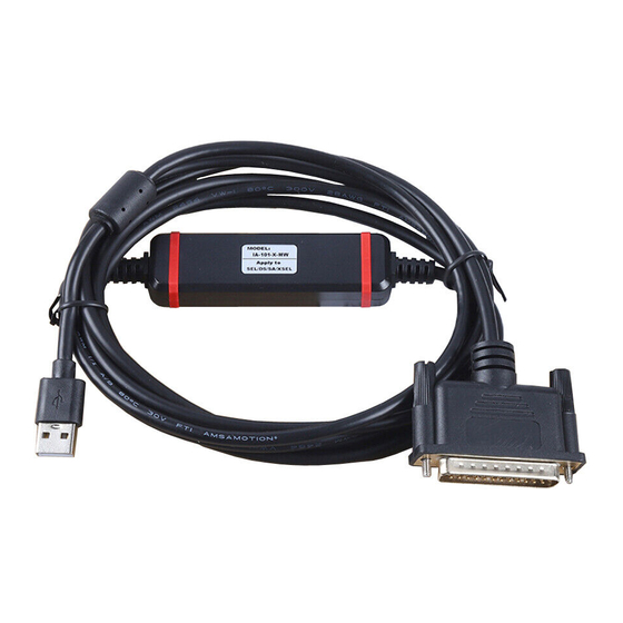
One set Enclosed connection cables vary depending on the PC interface software type. The types and connection cables are shown in the table below. Type External Connection Cable IA-101-X-MW-JS RS232C cable (CB-ST-E1MW050-EB): 1 cable Conversion cable (CB-SEL-SJS002): 1 cable IA-101-X-MW... - Page 24 Warning: The internal components of the controller may burn if the following cable is used to connect XSEL-Q, QX, S, SX, SA, SAX, SAXD to a computer. PC software IA-101-X-MW Accessory cable CB-ST-E1MW050 (black) Even though the PC software can be used, make sure to use the cable CB-ST-A2MW050 (gray).
-
Page 25: System Requirements
(The software is installed on the hard disk.) Serial port RS232C Required for PC software of the following model number: (EIA-S74 compliant) Model number: IA-101-X-MW-JS, IA-101-X-MW, IA-101-XA-MW USB port Required for PC software of the following model number: Model number: IA-101-X-USBS, IA-101-X-USBMW, IA-101-TT-USB, IA-101-TTA-USB,... -
Page 26: Installing The Software
Installing the Software This software is run from the hard disk. This section explains how to install the software. 1.3.1 How to Install the PC Interface Software for X-SEL If a version of the PC Interface Software earlier than V6.0.0.0 is already installed, first uninstall the PC Interface Software before installing V6.0.0.0. - Page 27 [3] The screen will change to the installation screen (Fig. 1.3) for PC interface software for X-SEL. Click Next >. Fig. 1.3 Installation Screen [4] The Customer Information registration screen (Fig. 1.4) will be displayed. Enter your information and click Next >.
- Page 28 [5] Specify a destination folder to install the PC interface software for X-SEL. (Fig. 1.5). Normally, you can install it to the displayed folder. After specifying it, click Next > Fig. 1.5 Specification of Destination Folder [6] The wizard is ready to begin installation. Clicking Install will begin actual installation. Fig.
- Page 29 Fig. 1.8 Installation Completion [8] Once the installation program is completed, the items of IAI, X_SEL, and PC Interface software will be displayed in this order from Program (P) in the Start menu. Selecting these items will start this software.
-
Page 30: How To Install The Usb Conversion Adapter Driver Software
1.3.2 How to Install the USB Conversion Adapter Driver Software When a USB port is used, it is required to install USB conversion adapter driver software. [Compatible software] • IA-101-X-USBS (with USB cable) • IA-101-X-USBMW (with USB conversion adapter + cable) •... - Page 31 [4] When the folder of IAI USB (copy data) already exists in the copy destination, you are prompted to overwrite it. Click OK to overwrite it, or click Cancel to stop copying. Fig. 1.12 Overwrite Confirmation Screen [5] The complete screen (Fig. 1.13) will be displayed.
- Page 32 [8] Then, insert the USB conversion adapter (IA-CV-USB) into the USB port of your PC. In the case of the SSEL/ASEL/PSEL/MSEL controller, TT or TTA (table top actuator), connect the PC and SSEL/ASEL/PSEL/MSEL controller, TT or TTA (table top actuator) with the attached USB cable. (Note) If the USB ports of PC and controller are connected directly with USB cables, each controller should be connected to each PC and use the USB Conversion Adapter Driver Software to let the...
- Page 33 Click Browse, and find and select “C: IAI USB.” Fig. 1.16 Search and Installation Options Selection Screen [12] The installation of the “IAI USB Composite Device” driver will begin. The wizard will prompt you with a warning to ask if you want to continue with the installation.
- Page 34 [13] When the IAI USB Composite Device driver installation finish is displayed, the installation of the driver is completed. Click Finish. Fig. 1.18 IAI USB Composite Device Installation Finish Screen [14] Subsequently, the Welcome to the Found New Hardware Wizard screen will open.
- Page 35 Fig. 1.20 Search and Installation Options Selection Screen [16] The installation of the “IAI USB to UART Bridge Controller” driver will begin. The wizard will prompt you with a warning to ask if you want to continue with the installation.
- Page 36 [17] The installation of the “IAI USB to UART Bridge Controller” driver is complete when the completion of the installation is displayed. Click Finish. Fig. 1.22 IAI USB to UART Bridge Controller Installation Completion Screen [18] The installation of all drivers is completed.
- Page 37 Fig. 1.24 Screen to Confirm Whether or Not an Older Version is Installed [4] The IAI Corporation USB to UART Bridge Controller Driver Installer screen appears. Click Next >. Fig. 1.25 IAI Corporation USB to UART Bridge Controller Driver Installer Screen...
- Page 38 [5] The drivers are now installing... screen appears. Fig. 1.26 The drivers are now installing Screen [6] It is displayed on the IAI Corporation USB to UART Bridge Controller Driver Installer screen, "The drivers were successfully installed on this computer". Click Finish.
- Page 39 [9] Launch Device Manager. Right-click “CP2102 USB to UART Bridge Controller” and click “Update Driver Software..” Fig. 1.28 Device Manager Screen [10] The Update Driver Software screen appears. On the Update Driver Software screen, click the “Browse my computer for driver software” button. Fig.
- Page 40 C: Program Files\IAI\IAI USBv4\Vista-8. Fig. 1.30 Update Driver Software Screen [12] The driver software update completion screen (IAI USB to UART Bridge Controller) appears. Click “Close” on the Update Driver Software screen. Fig. 1.31 Driver Software Update Completion Screen (IAI USB to UART Bridge Controller)
-
Page 41: How To Install Driver Software For Usb Connection Of Xsel-Ra/Sa/Rax/Sax/Raxd/Saxd
It is not necessary to have work processes from [1] to [5] for Windows 10. Go on to Step [6]. [1] Insert the CD-ROM containing this software into your CD-ROM drive. [2] The installed data selection screen will be displayed. Click the “Driver of USB for IAI Controller (for XSEL-RA/SA Series)”. - Page 42 [4] The installation of the driver will begin. The window shown below appears during the process. Continue operation in the steps shown in the figure. (The contents of the display may differ depending on the OS.) Click Install button Fig. 1.34 Install Start Screen (for Windows 7/8) Select Install this driver software anyway Fig.
- Page 43 Click Continue Anyway Fig. 1.36 Install Start Screen (for Windows XP) [5] After the install, the following window will open. Click Finish. Fig. 1.37 Devece Driver Install Wizard Complete Screen...
- Page 44 [6] Connect the personal computer to the controller using the USB cable. After connection being established, turn on the power to the controller if it is not on. [7] Installation process of the driver software automatically starts. [8] The following window may appear in some cases depending on the OS or PC environment. Continue operation in the steps shown in the figure.
- Page 45 (c) For Windows XP 1) Select Install the software automatically [Recommended] Click Next >. Fig. 1.40 Found New Hardware Wizard Click Continue Anyway Fig. 1.41 Hardware Installation Screen...
- Page 46 [9] Driver Software Installation install complete. (The contents of the display may differ depending on the OS) Click Close or Complete. Fig. 1.42 Driver Software Installation Complete Screen (For Windows 7) Fig. 1.43 Installation Complete Screen (For Windows XP) [13] The driver installation is now complete.
- Page 47 [Remarks] Once the installation of the USB driver is complete, COM port gets automatically added. [The way to change the COM port, refer to 1.3.4 How to Change COM Port of IAI USB” in XSEL PC Software Instruction Manual] (The name of the COM port is differ from the one on USB converter adapter) The names of COM port is “IAI...
-
Page 48: How To Change The Usb Com Port
(Note) COM? is the COM port number before the port is changed. IAI USB to UART Bridge Controller (COM?) Fig. 1.45 Device Manager Screen [3] Property screen of IAI USB to UART Bridge Controller (COM?) will be displayed. Click Options (A) on the Property screen. Fig. 1.46 Property Screen... - Page 49 [4] COM? Port Option screen will be displayed. Change the COM port number in the COM Port Number (P) box to the number to be set. Click OK. COM port number (P): Fig. 1.47 COM? Port Option Screen [5] COM? Port Option screen will be disappeared. COM port number will be changed by clicking OK on the Property screen (Fig.
-
Page 50: Connection To Controller
Connection to Controller Fig. 1.48 X-SEL-K (J) Type Controller... - Page 51 The internal components of the controller may burn if the following cable is used to connect XSEL-Q to a computer. PC software IA-101-X-MW Accessory cable CB-ST-E1MW050 (black) Even though the PC software can be used, make sure to use the cable CB-ST-A2MW050...
- Page 52 * Figure shows example of TT. Fig. 1.50 Table Top Actuator (TT, TTA)
- Page 53 Fig. 1.51 X-SEL-KX (JX) Type Controller...
- Page 54 The internal components of the controller may burn if the following cable is used to connect XSEL-QX to a computer. PC software IA-101-X-MW Accessory cable CB-ST-E1MW050 (black) Even though the PC software can be used, make sure to use the cable CB-ST-A2MW050...
- Page 55 The internal components of the controller may burn if the following cable is used to connect XSEL-S to a computer. PC software IA-101-X-MW Accessory cable CB-ST-E1MW050 (black) Even though the PC software can be used, make sure to use the cable CB-ST-A2MW050...
- Page 56 The internal components of the controller may burn if the following cable is used to connect XSEL-SX to a computer. PC software IA-101-X-MW Accessory cable CB-ST-E1MW050 (black) Even though the PC software can be used, make sure to use the cable CB-ST-A2MW050...
- Page 57 The internal components of the controller may burn if the following cable is used to connect XSEL-SXD to a computer. PC software IA-101-X-MW Accessory cable CB-ST-E1MW050 (black) Even though the PC software can be used, make sure to use the cable CB-ST-A2MW050...
- Page 58 The internal components of the controller may burn if the following cable is used to connect XSEL-SA to a computer. PC software IA-101-X-MW Accessory cable CB-ST-E1MW050 (black) Even though the PC software can be used, make sure to use the cable CB-ST-A2MW050...
- Page 59 The internal components of the controller may burn if the following cable is used to connect XSEL-SAX to a computer. PC software IA-101-X-MW Accessory cable CB-ST-E1MW050 (black) Even though the PC software can be used, make sure to use the cable CB-ST-A2MW050...
- Page 60 The internal components of the controller may burn if the following cable is used to connect XSEL-SAXD to a computer. PC software IA-101-X-MW Accessory cable CB-ST-E1MW050 (black) Even though the PC software can be used, make sure to use the cable CB-ST-A2MW050...
- Page 61 Emergency Stop Switch Enable Switch Conversion Cable USB Cable Mode Switch Panel Unit 1-axis 2-axis Fig. 1.59 SSEL Type Controller...
- Page 62 USB Cable Fig. 1.60 ASEL Type Controller...
- Page 63 USB Cable Fig. 1.61 PSEL Type Controller...
- Page 64 Teaching tool Actuator (IXP) (Note 1) Safety Circuit (Enable) Emergency (Note 1) Stop Actuator (RCP Series) Power supply (Single-phase Fieldbus AC100~230V) Host Device (Note 1) Absolute Battery (Note 1) Contact for Cutoff (when supplying / cutting off power source externally) Note1 Please prepare separately.
-
Page 65: Starting The Software (Online Connection)
Starting the Software (Online Connection) [1] Turn off the power to the controller and PC, and connect the controller to the PC using the standard RS232 cable or USB cable that comes with the software. Set the mode switch on the controller to the MANU side. - Page 66 [4] If XSEL-P/Q (application version 0.36 or later), XSEL-PX/QX (application version 0.17 or later), XSEL-R/S, XSEL-RX/SX, XSEL-RXD/SXD, XSEL-RA/SA, RAX/SAX, RAXD/SAXD, SSEL, ASEL, PSEL, or MSEL (application version 0.01 or later) is connected, the Two or more programs start permission/prohibition setting screen (Fig. 1.64) will be displayed. Set whether you prohibit or permit the simultaneous starting of multiple programs during the manual mode, and click the OK button.
- Page 67 P/Q type, PX/QX type, R/S type, RX/SX type, RXD/SXD type, RA/SA type, RAX/SAX type, RAXD/SAXD type, SSEL, ASEL, PSEL: Channel 0 (“OPEN 0”) The “Important” information provided in the above box applies to a condition where the controller is in the MANU mode and I/O parameter No. 90 is not set to “2” (IAI protocol).
-
Page 68: Operation System Command Restriction
Operation System Command Restriction A system was added to check to the user if there is a stop switch to stop the actuator immediately at hand, and if there is no stop switch, the actuator operation gets controlled from the XSEL PC software when connected with a controller. - Page 69 * Put a check mark on “Don’t show this window from next time on.” in the safety circuit confirmation window and the confirmation window for safety circuit will not show up again when the controller is connected. (Operation will be made with the setting of the previous connection) If it is required to show the safety circuit confirmation window again, put a check mark on “In connect, confirm safety circuit.”...
- Page 70 When “Yes” was selected in the previous safety circuit confirmation window and a check mark was put on “Don’t show this window from next time on.”, a warning message shown in the figure below will be displayed when a controller is connected. Click this button and Environment Setup window opens.
-
Page 71: How To Save Data
2. How to Save Data The controller adopts a flash memory. Accordingly, some data is stored in the memory areas backed up by a battery, while other data is stored in the flash memory areas. Also note that transferring data from the PC software or teaching pendant to the controller will only write the data in the controller’s memory, as illustrated below, and the data will be cleared once the controller power is turned off or the controller is reset. - Page 72 Position No. 10001-20000 and user retained memory (RC-axis position in XSEL) are added to X-SEL-P/Q, PX/QX controller with gateway function. (Other parameter No. 20 = “2” (Backup battery installed)) * Encoder parameters are stored in the EEPROM of the actuator’s encoder, not in the controller’s EEPROM. Therefore, encoder parameters will be loaded to the controller every time the controller power is turned on or a software reset is executed.
-
Page 73: When A Backup Battery Is Not Used (Table Top Actuator [Tt], Ssel, Asel, Psel)
Programs, parameters and symbols are loaded from the flash memory after the controller is restarted. Unless written to the flash memory, edited programs, parameters and symbols will return to the original data once the controller is restarted. The controller always operates according to the data (excluding parameters) stored in its memory (indicated by dotted lines). - Page 74 Position No. 10001-20000 and user retained memory (RC-axis position in XSEL) are added to X-SEL-P/Q, PX/QX controller with gateway function. (Other parameter No. 20 = “0” (Backup battery not installed)) Programs, parameters and symbols are loaded from the flash memory after a restart. Unless written to the flash memory, edited programs, parameters and symbols will return to the original data once the controller is restarted.
-
Page 75: Xsel-R/S/Rx/Sx/Rxd/Sxd
XSEL-R/S/RX/SX/RXD/SXD An example of 20,000 positions is given below. Data editing on the Data retained while the power Data retained after the power PC or teaching is on and cleared after reset is turned off pendant Main CPU flash memory Main CPU RAM memory Programs Parameters (other than slave... -
Page 76: Xsel-Ra/Sa/Rax/Sax/Raxd/Saxd
XSEL-RA/SA/RAX/SAX/RAXD/SAXD Data editing on the Data retained while the power Data retained after the power PC or teaching is on and cleared after reset is turned off pendant Main CPU RAM memor Main CPU flash memory Programs Parameters (other than sleve card parameters) Write to flash Symbols... -
Page 77: Tta
Editing data in PC and teaching Retain data while power ON Retain data even when power OFF pendant Delete data at reset Main CPU RAM memory Main CPU flash memory Program parameter Flash writing (Other than driver Transfer card parameter) Symbol position (No.10001 to 30000) Transfer at reset... -
Page 78: Msel
MSEL E d it ing da t a in P C and R e t a in da t a w h ile po w e r O N R e t a in da t a e v en w hen po w e r O F F t ea c h ing pendan t D e le t e da t a a t re s e t M a in C P U R A M... -
Page 79: Notes
Notes Note on transferring data and writing it to the flash memory: Never turn off the main power while data is still being transferred or written to the flash memory. The data may be lost and the controller operation may be disabled. Note on saving parameters to a file: Encoder parameters are saved in the EEPROM of the actuator’s encoder (unlike other parameters, they are not stored in the controller’s EEPROM). - Page 80 Note on the increased number of parameters: The number of the parameters has been increased for the X-SEL-P/Q, PX/QX controllers (w/gateway function) compatible with increased memory. The Number of Parameters X-SEL-PX/QX X-SEL-P/Q, PX/QX X-SEL-P/Q incompatible incompatible with compatible with with increased memory increased memory increased memory For all axes...
-
Page 81: Menu Window
3. Menu Window Explanation of the Menu 3.1.1 Online Screen (1) X-SEL-J/K or TT controller When this software has been started, the main window in Fig. 3.1 will open showing the menu items with icons on the tool bar in the case of the X-SEL-J/K or TT controller. The tree view appearing on the left side of the window can be displayed by clicking View (V) from the menu bar and then selecting Tree View (T). - Page 82 (2) X-SEL-P/Q, R/S, RA/SA, TTA and MSEL controllers When this software has been started, the main window in Fig. 3.2 will open showing the menu items with icons on the tool bar in the case of the X-SEL-P/Q, R/S and TTA controllers. The tree view appearing on the left side of the window can be displayed by clicking View (V) from the menu bar and then selecting Tree View (T).
- Page 83 (4) X-SEL-PX/QX, RX/SX, RXD/SXD, RAX/SAX, RAXD/SAXD and MSEL-PCX/PGX controllers When this software has been started, the main window in Fig. 3.2 will open showing the menu items with icons on the tool bar in the case of the X-SEL-PX/QX, RX/SX, RXD/SXD and MSEL-PCX/PGX controllers. The tree view appearing on the left side of the window can be displayed by clicking View (V) from the menu bar and then selecting Tree View (T).
- Page 84 (6) SSEL controller in the positioner mode When this software has been started, the main window in Fig. 3.6 will open showing the menu items with icons on the tool bar in the case of the SSEL controller in the positioner mode. The tree view appearing on the left side of the window can be displayed by clicking View (V) from the menu bar and then selecting Tree View (T).
-
Page 85: Offline Screen
(8) PSEL controller When this software has been started, the main window in Fig. 3.8 will open showing the menu items with icons on the tool bar in the case of the PSEL controller. The tree view appearing on the left side of the window can be displayed by clicking View (V) from the menu bar and then selecting Tree View (T). -
Page 86: Explanation Of The Commands
Explanation of the Commands (1) File (F) [1] New (N) Create new SEL data. • Program (S) Open the edit window for creating a new program. • Position (O) Open the edit window for creating new position data. This menu item will become faint-colored and render the command inoperable in the case of the SSEL, ASEL, and PSEL controllers in the positioner mode. - Page 87 (1) File (F) (continued) Close (C) Close the currently active window. Save (S) Save the data in the active edit window by overwriting the corresponding file. Save As (A) Save the data in the active edit window to a different file under a desired name.
- Page 88 (1) File (F), [6] Print Setting (P) (continued) In PC software V9.00.00.00 or later, whether or not to print the folder name can be selected. If this check box is selected, the folder name will not be printed when the file data is printed. If this check box is selected, the folder name will not be printed when...
- Page 89 (2) Edit (E) This menu lets you perform operations used in editing data. Undo (U) Up to the most recent 10 operations can be canceled. However, they cannot be canceled when you perform any of the following operations: • Transfer of data on the editing screen such as the program edit window to the controller •...
- Page 90 (4) Program (S) This menu lets you perform operations relating to programs. (Available only in the online mode.) (Refer to “4. Program Edit Window.”) [1] Edit (E) Load a selected program from the controller for editing. Cycle time can be measured in XSEL-RA/SA/RAX/SAX/RAXD/SAXD (main CPU application version V1.10 and later).
- Page 91 (6) Parameter (P) This menu lets you operate parameters. (Available only in the online mode.) (Refer to “8. Parameter Edit Window.”) [1] Edit (E) Load position parameters from the controller for editing. [2] Easy Parameter Setup (S) Parameter edit is to be conducted in the setting screen of each feature for those features listed below.
- Page 92 (9) Monitor (M) This menu lets you monitor various statuses, global variables, port statuses, and so on. (Available only in the online mode.) (Refer to “11. Monitor.”) Open the task status monitor window. [1] Task Status (T) Open the system status monitor window. [2] System Status (S) Open the axis status monitor window.
- Page 93 Change Baud Rate (B) Change the baud rate used for communication between the controller and Offline Operation (Communication port close) (O) RC Gateway (Y) Operational manual for gateway function is in a separate volume. Operational manual Management number X-SEL controller P/Q/PX/QX and R/S/RX/SX/RXD/SXD ME0188 RC gateway function...
- Page 94 (10) Controller (C) [7] All Data Backup (X) ▪ Save to File (S) (continued) [When the RC-axis position data in RC controller is used] RC-axis position data in RC controller can not be saved in the PC interface software for X-SEL. Fig.
- Page 95 (10) Controller (C) [7] All Data Backup (X) ▪ Transfer to Controller/Divide File (L) (continued) The following section explains about “Transfer to Controller” and “Divide File.” ▪ Transfer to Controller On the Data Transfer/Division Selection Screen, click Transfer to Controller. The File Setup Screen will appear. Select Backup All Saved Data (all data including programs, positions, etc.) and transfer to the controller.
- Page 96 (10) Controller (C) [7] All Data Backup (X) ▪ Transfer to Controller/Divide File (L) (continued) [When RC-axis position data in RC controller is used] RC-axis position data in RC controller cannot be transferred in PC interface software for X-SEL. Fig. 3.25 Warning Screen (Transferring RC-axis position data when position data in RC is used.) When a user data retained memory with a different composition is transferred, the following warning screen will be displayed.
- Page 97 (10) Controller (C) [7] All Data Backup (X) ▪ Transfer to Controller/Divide File (L) (continued) • Divide Files Divide all the saved backup data (all data including program and position) into program, position, parameter, symbol, X-SEL-JX/KX, PX/QX, RX/SX/RXD/SXD,RAX/SAX/RAXD/SAXD and MSEL-PCX/PGX axis data. Click Divide Files on the Transfer/Divide data screen.
- Page 98 (10) Controller (C) (continued) [10] Restoration of Data Written into Flash ROM (for 1 generation before) (Q) This item is displayed for TTA, MSEL controller. • Program (S) Restore the program data written into Flash ROM to the written data for 1 generation before.
- Page 99 (10) Controller (C) (continued) ▪ User Data Retained Memory (U) In the case of X-SEL-P/Q/PX/QX, R/S/RX/SX/RXD/SXD, RA/SA/RAX/SAX/RAXD/SAXD with gateway function, clear all the contents of user data retained memory containing RC-axis position data in X-SEL controller. (PC interface software version 7.2.0.0 or later) * If the Edit screen for RC-axis position (in X-SEL-P/Q/PX/QX and R/S/RX/SX/RXD/SXD controllers) is opened without resetting the software or turning off the power after performing this operation and...
- Page 100 (10) Controller (C) (continued) [19] Operation-pause Reset Request (L) Issue an operation-pause reset request to the controller. [20] Set Time (T) Set time. This function is available on the XSEL-R/RX/RXD/S/SX/SXD, XSEL-RA/RAX/RAXD/SA/SAX/SAXD, TTA and MSEL controller. [21] About ROM Version (V) Show the various ROM version information regarding the controller. [22] Control Constant Table Management Information (Z) Show the control constant table management information.
-
Page 101: Explanation Of The Toolbar
Explanation of the Toolbar This section explains the toolbar (Fig.3.29) shown at the top of the main window (below the menu bar). Fig. 3.29 Toolbar (Other than TTA, MSEL) Open File Same as clicking File (F) and then selecting Open (O). Save Same as clicking File (F) and then selecting Save (S). - Page 102 This list box is used to enable/disable the safety velocity limit in the manual mode. [Safety Vel Specified] --- Enable the safety velocity limit. (The maximum speed during CP operation will be limited to 250 mm/sec or below [PTP operation: 3% or below] regardless of program or parameter settings.) [Safety Vel Not Specified] --- Disable the safety velocity limit.
-
Page 103: Tree View
Tree View You can display various data edit windows in the online mode by double-clicking the corresponding items displayed in the tree view (Fig. 3.31, Fig. 3.32) that appears on the left side of the main window. You can show or hide the tree view by clicking View (V) from the menu bar and then selecting Tree View (T). Controller model The example of Fig. - Page 104 Controller model The example of Fig. 3.32 also applies to X-SEL-PX/QX, RX/SX/RXD/SXD, RAX/SAX/RAXD/SAXD and MSEL-PCX/PGX controllers. Remaining steps that can be stored in the controller Currently registered programs Number of registered steps in ( ) Program name in [ ] (if a symbol is registered) Unregistered programs Position data edit item Double-click to open the position edit window.
-
Page 105: Program Edit Window
4. Program Edit Window Explanation of the Items Displayed in the Program Edit Window (1) Click Program (S) from the menu bar, and then select Edit (E). (2) When the program number selection window opens, select the program you want to edit, and then click Load. - Page 106 Fig. 4.2 Program Edit *1 Only XSEL-RA/SA, RAX/SAX and RAXD/SAXD are available for setting with binary and hexadecimal systems in Operand1 and Operand2. Fig.4.3 Setting with Binary and Hexadecimal Systems [How to set up] When using the binary numbers, apply “&B” at the top of the value. When using the hexadecimal numbers, apply “&H”...
- Page 107 If even one line is changed, all step numbers will be displayed in red. Right-clicking a desired input item in each line will display a pop-up menu (Fig. 4.4). The items in the pop-up menu are explained below. Cut (T) Same as clicking Edit (E) from the menu bar and then selecting Cut (T).
- Page 108 In the program edit window, selecting Edit (E) from the menu and then Undo (U) can cancel up to the most recent 10 operations. Alternatively, pressing the Ctrl key and Z key simultaneously can cancel the operations. However, the cancel function will become disabled when any of the following operations is performed: Transfer of data on the edit screen to the controller ...
- Page 109 Right-clicking on the SEL Command Explanation window will open a pop-up menu containing the following items. Input (I) Input the command in the cursor line to the step data (into the cursor line in the program edit window). Font (F) You can set a desired font for displaying the SEL command explanations.
- Page 110 (4) This window has the various buttons shown below. (a) (b) (c)(d) (e) (f) (g) (h) (I) (j) (k)(l) Fig. 4.8 Buttons (a) Save to File (f) Run 1 Step Click this button to save the program in a file with The program will run one step every time this a name.
- Page 111 (5) Checking the program The software will check the program you have created, for SEL syntax errors. [1] Click the Check Program button in the program edit window. [2] If any error is found, the error list will be displayed. Check Program button Fig.
- Page 112 [a] Syntax Error Message (error content) [b] Variable No. Use Condition Variable No. Category (Integer, real number) Scope (Global, local) * If the applicable variable number is specified indirectly, the Category and Scope fields will show “Unknown.” [c] Input/Output/Flag No. Port/Flag No.
-
Page 113: Saving A Program, Transferring And Closing The Edit Window
Saving a Program, Transferring and Closing the Edit Window 4.2.1 Saving a Program Online, Transferring and Closing the Edit Window (1) Saving to a file the program data you are editing Click the Save to File button in the program edit window. This is the same as clicking File (F) and then selecting Save As (A). - Page 114 (3) Writing to the flash ROM Once the program has been transferred to the controller, the following confirmation dialog box with the message, “Write Flash ROM?” will be displayed. Fig. 4.13 Confirmation Fig. 4.14 Confirmation (X-SEL-J/K, P/Q, TT, SSEL, ASEL, PSEL, (X-SEL-JX/KX, PX/QX) TTA, MSEL-PCX/PGX) In case of SSEL, ASEL, PSEL, X-SEL-P/Q and PX/QX compatible with increased memory (with gateway...
- Page 115 (4) Closing the program edit window Attempting to close the program edit window will display the following confirmation dialog box with the message, “Save edited data in the Controller?” Fig. 4.17 Confirmation Yes (Y) The edited data will be transferred to the controller → (3), “Writing to the flash ROM” No (N) The software will close the program edit window without saving the edited data.
-
Page 116: Transferring A Program Created Offline
4.2.2 Transferring a Program Created Offline A program created offline can be transferred to a controller by following the steps below. (1) Select File → Open from the menu. In the screen of “Open File”, select a program created offline and open it. (2) If a controller is connected, Controller Transfer button gets activated once the program is opened. - Page 117 (4) Next, a screen to select the program number for destination will be shown. Click on a program number line for destination to select a destination. Press Write. Fig.4.20 Program No. Select (5) A confirmation screen stating “Write Flash ROM” will appear. Press Yes.
-
Page 118: Saving All Programs To A File
Saving All Programs to a File (1) Saving all programs to a file You can save programs No. 1 to 64 in the controller (or programs No. 1 to 128 for XSEL-P/Q and PX/QX (with gateway function) complied with increased memory, or programs No. 1 to 128 for R/S, RX/SX and RXD/SXD, compatible with increased memory SSEL or programs No. - Page 119 (3) Important note on transferring an all programs file to the controller [1] Transferring all program files to a controller at once will clear all existing programs No. 1 to 64 ( or programs No. 1 to 128 for XSEL-P/Q and PX/QX (with gateway function) complied with increased memory, or programs No.
- Page 120 [5] If the data saved by the Program File Format 2 (extended format) is transferred to a controller incompatible with increased memory, the programs of No.65 or later will not be transferred. The following warning screen will be displayed. Clicking Yes will transfer all programs. Clicking No will not transfer all programs.
-
Page 121: Running The Program
Running the Program You can run the program in the program edit window. To run the program you are editing, transfer it to the controller first. Note) Once transferred to the controller, the program can be run without being written to the flash ROM first. -
Page 122: Cycle Time Measurement
Cycle Time Measurement Target Controller : XSEL-RA/SA/RAX/SAX/RAXD/SAXD (Main CPU application version V1.10 and later) By setting up the measurement start point and end point in the program, the cycle time during program operation can be measured. (V13.02.00.00 and later) 4.5.1 How to Measure Cycle Time Select Program (S) ... - Page 123 [1] Setting of Cycle Time Measurement Area Section (Note) The section of area to be set up should be just one section. Two or more sections cannot be established. (Note) When establishing the input / extension status setting, set S and E in the command (Cmnd column) description step.
- Page 124 (2) Measurement One Step Setup [1] Right-click on Column T (blank cell) of the step that you would like to measure. S: Measurement start point will be displayed. Fig. 4.32 Measurement start point Setup [2] Secondly, right-click on the point that S is being displayed. SE: The measurement point will be displayed.
- Page 125 Follow the steps below when it is required to set up again or cancel the items that you have already set up. When S and E are displayed right-click on the cell of S, and S will be erased. If E is displayed, it means that the measurement area section setting is not activated.
- Page 126 [2] Displaying Cycle Time Measurement Result Once a program gets operated, cycle time will be measured and the result will be displayed at the position marked in red. Once the program starts executed and the step with “S” being shown gets executed, measurement will start and display shows -----.---s.
- Page 127 [Note] Measurement keeps executed unless the execution of the step with E displayed in Column T is completed. In case setting is established in an area section that is looped in short period of time, it could seem as if -----.---s is kept displayed because measurement will start straight after the previous measurement is finished.
-
Page 128: Copying/Moving/Clearing A Program
5. Copying/Moving/Clearing a Program Program Copy/Move Window The steps to copy or move a program to other program number are explained below. Click Program (S) from the menu bar, and then select Copy/Move (C). The program copy/move window will open. Program number to copy/move from Program number to copy/move to In the case of the SSEL, ASEL, or PSEL... - Page 129 In case of SSEL, ASEL, PSEL, X-SEL-P/Q and PX/QX compatible with increased memory (with gateway function), R/S, RX/SX, RXD/SXD, RA/SA, RAX/SAX and RAXD/SAXD the following screens will be displayed. (PC interface software version 7.2.0.0 or later) This is not displayed for XSEL-RA/SA, RAX/SAX, RAXD/SAXD, SSEL,...
-
Page 130: Program Clear Window
Program Clear Window The steps to clear a program are explained below. (1) Click Program (S) from the menu bar, and then select Clear (L). (2) The program clear window will open. In the case of the SSEL, ASEL, and PSEL controllers, the number of remaining steps will be 2000 or less. - Page 131 In case of SSEL, ASEL, PSEL, RA/SA, RAX/SAX, RAXD/SAXD, X-SEL-P/Q and PX/QX compatible with increased memory (with gateway function), or R/S, RX/SX and RXD/SXD, the following screens will be displayed. (PC interface software version 7.2.0.0 or later) This is not displayed for XSEL-RA/SA, RAX/SAX, RAXD/SAXD, SSEL,...
-
Page 132: Position Data Edit Window
6. Position Data Edit Window Explanation of the Items Displayed in the Position Data Edit Window (1) Click Position (O) from the menu bar, and then select Edit (E). (2) The position data window (Edit Position Data) will open. This window has the following controls and fields. (5) Setting functions (Orthogonal axis) (1) Position data (2) Common buttons (4) Axis-specific buttons (Orthogonal axis) - Page 133 (1) Position data (6) Axis-specific buttons (SCARA axis) (8) Movement selection (3) Common buttons (7) Setting functions (SCARA axis) Fig. 6.4 Position Data Edit (X-SEL-JX/KX) (1) Position data Fig. 6.5 Position Data (X-SEL-JX/KX) (1) Position data (2) Common buttons (6) Axis-specific buttons (SCARA axis) (7) Setting functions (SCARA axis) (8) Movement selection (5) Setting functions (Orthogonal axis) (1) Position data...
- Page 134 (4) Axis-specific buttons (5) Setting functions (1) Position data (2) Common buttons (Orthogonal axis) (Orthogonal axis) Fig. 6.8 Position Data (XSEL-R/S, RA/SA) (1) Position data Fig. 6.9 Position Data (XSEL-R/S) For XSEL-RA/SA, the following position output operation data is displayed in the position edit data. 10) Position output operation data Fig.
- Page 135 Movement setting (6) Axis-specific buttons (SCARA axis) (1) Position data (2) Common buttons (9) Axis-specific button/setting function/movement setting display axis switching SCARA axis setting (7) Setting functions (SCARA axis) (4) Axis-specific Orthogonal buttons axis (Orthogonal setting axis) (5) Setting functions (Orthogonal axis) Fig.
- Page 136 (1) Position data Fig. 6.13 Position Data (X-SEL-RX/SX) For XSEL-RAX/SAX, the following position output operation data is displayed in the position edit data. 10) position output operation data Fig. 6.14 Position Data (XSEL-RAX/SAX) (2) Common buttons (6) Axis-specific buttons (SCARA axis) Movement setting (1) Position data (9) Axis-specific button/setting function/movement setting display axis switching...
- Page 137 (1) Position data Fig. 6.17 Position Data (X-SEL-RXD/SXD) For XSEL-RAXD/SAXD, the following position output operation data is displayed in the position edit data. 10) Position output operation data Fig. 6.18 Position Data (XSEL-RAXD/SAXD) (2) Common buttons (4) Axis-specific buttons (Orthogonal axis) (5) Setting functions (Orthogonal axis) (1) Position data Data in the change line will be displayed in red.
- Page 138 (1) Position data Fig. 6.20 Position Data (SSEL, ASEL and PSEL) (7) Setting functions (4) Axis-specific buttons (1) Position data (SCARA axis) (2) Common buttons (8) Movement selection Fig. 6.21 Position Data Edit (MSEL-PCX/PGX Controller) Fig. 6.22 Position Data (MSEL-PCX/PGX) No.
- Page 139 Axis 1 to 4 Specify each desired position for Axis 1 to Axis 4. In the case of the JX/KX, PX/QX, RX/SX, RXD/SXD, RAX/SAX, RAXD/SAXD, and MSEL-PCX/PGX controllers, specify a desired position for each SCARA axis. The setting range is from –99999.999 to 99999.999. Axis 5, 6 Specify a desired position for Axis 5 and Axis 6.
- Page 140 Specify a desired deceleration. Available range is from 1 to 9.99. However, for X-SEL-PX/QX, 1 to 4 axes, bigger one between from 0.01 to All Axis Common Parameter No. 23 “SCARA Axis CP Deceleration Maximum” and Parameter No. 204 “Linear Axis Deceleration Maximum”...
- Page 141 (2) Common buttons (X-SEL-J/K, P/Q, PX/QX, R/S, RX/SX, Fig.6.25 Common Buttons (X-SEL-J/K, P/Q, PX/QX, R/S, RX/SX, RA/SA, RAX/SAX, RA/SA, RAX/SAX, TT, TT, SSEL, ASEL, PSEL, TTA and MSEL) SSEL, ASEL, PSEL, TTA and MSEL) (3) Common buttons (X-SEL-JX/KX, RXD/SXD and Fig.
- Page 142 Jog – This button is not displayed for X-SEL-JX/KX. The axes specified as the ones to be operated by the common buttons and whose servo is ON will jog backward while this button is pressed. However, axis specification has limitations. Jog + This button is not displayed for X-SEL-JX/KX.
- Page 143 Move Continuously Clicking this button will move all axes indicated by (in the case of the SCARA axis, the 1st arm, 2nd arm, and R-axis are interlocked) to the position of the position number corresponding to the cursor position. Thereafter, each axis will continue to move to the position set by the data in next position number.
- Page 144 (4) Axis-specific buttons (Orthogonal axis) (Note) The display on SCRA axis of MSEL-PCX/PGX is the same. The axis you want to move using the common buttons Current position of the selected axis Error code Fig. 6.29 Axis-specific buttons (Orthogonal axis) Axis number Select the axis to be operated Error code...
- Page 145 (5) Setting functions (Orthogonal axis) Set the velocity (Vel), acceleration (Acc), deceleration (Dcl) and inching distance (Inc.) to be used when the actuator is operated using the various buttons. If a value is entered in any of the Vel, Acc and Dcl fields in the position data area, the value in the applicable position data field will be given priority for movement to the corresponding position number.
- Page 146 (6) Axis-specific buttons (SCARA axis) Axis number Select the axis you want to move using the common buttons. Current position of the selected axis "W" in the case of the work coordinate system or "A" in the case Error code of each axis system Fig.
- Page 147 (7) Setting functions (SCARA axis) Set the velocity (Vel), acceleration (Acc), deceleration (Dcl) and inching distance (Inc.) to be used when the actuator is operated using the various buttons. Fig. 6.36 Settings of Velocity, Acceleration, Deceleration and Inching Distance Jog/Inc Vel [mm/sec], Acc [G], Dcl [G], Inc [mm] The above settings are effective on both the work and tool coordinate systems.
- Page 148 (8) Movement Selection Various buttons are provided to set Current arm system, Jog movement coordinate system, Work coordinate system select No. and Tool coordinate system select No. Fig. 6.38 Selection of Current Arm System and Various Coordinate Systems Current arm system The arm can be changed by clicking the Change button.
- Page 149 (9) Axis-specific button/setting function/movement selection display axis switching Fig. 6.44 Axis-specific Button/Setting Function/Movement Selection Display Axis Switching. Switch the axes displayed in the axis-specific button, setting function and movement selection areas. Axis1-8: Display the axis-specific buttons, setting functions and movement selections of all effective axes. (This item is displayed only when the X-SEL-PX/QX, RX/SX, RXD/SXD and RAX/SAX, RAXD/SAXD controllers are connected and Axis 5 and subsequent axes are effective axes.) Axis1-4: Display the axis-specific buttons, setting functions and movement selections only for SCARA...
- Page 150 [Output Function Code] Turns ON/OFF after movement:It turns ON/OFF the specified output ports and flags after moved to the ● applicable position. Turns ON/OFF after passed specified distance:It turns ON/OFF the output ports and flags at the position ● where proceeded from the movement start position for the distance specified in Function Parameter 1 during movement to the applicable position.
- Page 151 Display of Output Port (V11.00.00.00 and later) Output port can be displayed on position edit window. To show the display, it is necessary to establish the following parameter settings. I/O Parameter Name Setting Details Number of Use of PC/TP User Set the number of output ports to be displayed on No.74 Output Ports (such as hand)
-
Page 152: Saving Position Data, Transferring And Closing The Edit Window
Saving Position Data, Transferring and Closing the Edit Window 6.2.1 Saving a Program Online, Transferring and Closing the Edit Window (1) Saving to a file the position data you are editing Click the Save to File button in the position edit window. This is the same as clicking File and then selecting Save As. - Page 153 Error/warning display before data transfer When transferring position data to the controller, the position data to be transferred is checked for problems and if any of the data cannot be transferred (due to excessive speed, acceleration, deceleration, etc.), applicable errors/warnings are displayed in a list. Select the "Show errors only"...
- Page 154 (3) Writing to the flash ROM Once the position has been transferred to the controller, the following confirmation dialog box with the message, “Write Flash ROM?” will be displayed. Fig. 6.51 Confirmation Fig. 6.52 Confirmation (X-SEL-J/K, P/Q, TT, SSEL, ASEL, PSEL, (X-SEL-JX/KX, PX/QX) TTA, MSE-PCX/PGX) In case of SSEL, ASEL, PSEL, X-SEL-P/Q and PX/QX compatible with increased memory (with gateway...
- Page 155 (4) Closing the point edit window Attempting to close the point edit window will open the following confirmation dialog box with the message, “Save edited data in the Controller?” Fig. 6.55 Confirmation Yes (Y) The edited data will be transferred to the controller → (3), “Writing to the flash ROM” No (N) The software will close the point edit window without saving the edited data.
-
Page 156: Transferring A Position Created Offline
6.2.2 Transferring a Position Created Offline A position created offline can be transferred to a controller by following the steps below. (1) Select File → Open from the menu. In the screen of “Open File”, select a position created offline and open it. (2) If a controller is connected, Controller Transfer button gets activated once the position is opened. - Page 157 (4) Next, a screen to select the position number for destination will be shown. Select numbers to indicate transfer from what number to what number of the positions to be performed. Press OK. Fig.6.58 Position No. Select (5) A confirmation screen stating “Write Flash ROM” will appear. Press Yes.
-
Page 158: Copying/Moving/Clearing Position Data
7. Copying/Moving/Clearing Position Data Copying/Moving Position Data (1) Click Position (O) from the menu bar, and then select Copy/Move (C). (2) The position data copy/move window (Copy/Move Position Data) will open. Copying position data: In Source to Copy/Move, specify the Top No. and Last No. of the position range you want to copy or move. - Page 159 In case of SSEL, ASEL, PSEL, X-SEL-P/Q and PX/QX compatible with increased memory (with gateway function), R/S, RX/SX, RXD/SXD, RA/SA, RAX/SAX and RAXD/SAXD the following screens will be displayed. (PC interface software version 7.2.0.0 or later) This is not displayed for XSEL-RA/SA, RAX/SAX, RAXD/SAXD, SSEL, ASEL and PSEL.
-
Page 160: Clearing Position Data
Clearing Position Data (1) Click Position (O) from the menu bar, and then select Clear (L). (2) The position data clear window (Clear Position Data) will open. Fig. 7.6 Clear Position Data In Clear Scope, specify the Top No. and Last No. of the position range you want to clear. Then, click Clear. - Page 161 In case of SSEL, ASEL, PSEL, X-SEL-P/Q and PX/QX compatible with increased memory (with gateway function), R/S, RX/SX, RXD/SXD, RA/SA, RAX/SAX, RAXD/SAXD the following screens will be displayed. (PC interface software version 7.2.0.0 or later) This is not displayed for XSEL-RA/SA, RAX/SAX, RAXD/SAXD, SSEL, ASEL and PSEL.
-
Page 162: Parameter Edit Window
8. Parameter Edit Window Explanation of the Parameter Edit Window (1) Click Parameter (P) from the menu bar, and then select Edit (E). (2) The parameter edit window (Edit Parameter) will open. You can select a desired parameter and change the value. Values that are grayed out are read-only and cannot be changed. - Page 163 In the parameter edit window, clicking Edit (E) from the menu bar and then selecting Undo (U) can cancel up to the most recent 10 input operations. Alternatively, pressing the Ctrl key and Z key simultaneously can cancel the operations. However, the cancel function will become disabled when any of the following operations is performed: ...
-
Page 164: Saving Parameter Data And Closing The Edit Window
Saving Parameter Data and Closing the Edit Window (1) Saving to a file the parameter data you are editing Click the Save to File button in the parameter edit window. This is the same as clicking File (F) and then selecting Save As (A). (2) Transferring to the controller the parameter data you are editing You can save the parameter data you are editing to the controller’s memory. - Page 165 (3) Writing to the flash ROM Once the parameter has been transferred to the controller, the following confirmation dialog box with the message, “Write Flash ROM?” will be displayed. Fig. 8.3 Confirmation Fig. 8.4 Confirmation (X-SEL-J/K, P/Q, TT, SSEL, ASEL, PSEL, (X-SEL-JX/KX, PX/QX) TTA, MSEL-PCX/PGX) In case of SSEL, ASEL, PSEL, X-SEL-P/Q and PX/QX compatible with increased memory (with gateway...
- Page 166 (4) Restarting the controller (software reset) After the data has been written to the flash ROM, the following confirmation dialog box with the message, “Restart the controller” will be displayed. The new parameters will become effective. The new parameters will not become effective. The parameters will become effective after the controller is restarted (software reset) or the controller power is reconnected.
-
Page 167: Transferring A Parameter File
Transferring a Parameter File Pay attention to parameter categories when transferring parameter data files to the controller. The controller is shipped with its axis-related parameters set, for each axis, to values appropriate for the type of the actuator connected. There are three categories of axis-related parameters: axis-specific parameters, driver card parameters and encoder parameters. -
Page 168: Selecting Categories Of Parameters To Be Transferred
8.3.1 Selecting Categories of Parameters to Be Transferred (1) Select Open from the File menu or click the corresponding button in the toolbar. In the file selection dialog box, select the parameter file (extension: .xpm) you want to transfer to the controller. Load the file into the PC software and open the parameter edit window. - Page 169 Fig. 8.11 Select Parameter Category Window (X-SEL-JX/KX) (This window is supported by PC software version 3.0.1.0 or later.) Fig. 8.12 Select Parameter Category Window (SSEL, ASEL, PSEL) (This window is supported by PC software version 3.0.1.0 or later.) [1] Transfer parameters list The parameters to be transferred to the controller are displayed in accordance with the selections made in [2] through [5] explained below.
- Page 170 [2] General parameter categories Click the checkbox corresponding to each category of parameters you want to transfer (the clicked checkbox will be selected). Only the parameters of the selected category or categories will be transferred to the controller. [3] Parameter transfer options – Select parameter transfer options Of the parameters selected in the General parameter categories group, select whether to transfer actuator-related parameters only, transfer non-actuator parameters only, or transfer all selected parameters.
-
Page 171: Default Specifications
Note) In case the numbers of axes differ between the controller side and file side for IXA SCARA Robot (3-axis and 4-axis types), sending and receiving of parameters related to each axis should not be available. [5] Parameter transfer options – Controller basic unit Transmit options Select whether to enable transfer of controller basic unit dependent parameters. -
Page 172: Easy Parameter Setup
• Fieldbus (CC-Link, DeviceNet, PROFIBUS-DP, EtherCAT) Setup of Fieldbus communication and I/O assignment can be conducted. • Ethernet Setup of I/O communication, IAI protocol B/TCP communication and program message communication by Ethernet can be conducted. • Vision System Setup of Vision System I/F feature can be conducted. - Page 173 The top menu of Easy Parameter Setup appears. Click on a button for a feature of which you would like to set up or change the parameter. Fig. 8.17 Easy Parameter Setup Top Menu (Note) For some controllers, Fieldbus button may be replaced with a network name that is equipped to a controller.
- Page 174 (3) For example, if you click RS232C button, the setup window for RS232C will appear. Set up or change the parameters. 1) Set up or change parameters 2) Click “Transmit to Controller” Fig. 8.18 Example for Setup Window (RS-232C) After setting up or changing the parameters, click Transmit to Controller and the setup change data gets transmitted to the controller and the setup window closes.
- Page 175 (Note) To have Easy Parameter Setup, it is necessary that .NET Framework 4.0 (Full) or 4.5 is installed to the PC on which the PC software for X-SEL is used. If attempting to install the PC software for X-SEL (V12.02.00.00 or later) to a PC that .NET Framework 4.0 (Full) or 4.5 is not installed, installation window for .NET Framework 4.0 (Full) will appear.
- Page 176 [Caution 1] Administrative permission is required to install .NET Framework 4.0 (Full). Log in to the user with the administrative permission for installation. [Caution 2] If .NET Framework 4.0 (Full) is installed to Windows XP, .NET Framework 1.0 gets disabled to install. When it is necessary to use .NET Framework 1.0, install .NET Framework 1.0 before installing .NET Framework 4.0 (Full).
-
Page 177: How To Initialize Xsel-R/S, Rx/Sx, Rxd/Sxd, Ra/Sa, Rax/Sax, Raxd/Saxd, Ssel, Asel, Psel
How to Initialize XSEL-R/S, RX/SX, RXD/SXD, RA/SA, RAX/SAX, RAXD/SAXD, SSEL, ASEL, PSEL, MSEL high resolution type, TTA AC servo type / high resolution type Parameters (at the time of shipment) Note: Initialization of parameters (at the time of shipment) can be performed only for XSEL-R/S, RX/SX, RXD/SXD, RA/SA, RAX/SAX, RAXD/SAXD, SSEL, ASEL, PSEL, MSEL-PCX/PGX, PC/PG Controller high resolution type and TTA AC servo type / high resolution type. - Page 178 (3) Selecting the displayed menu Parameter of Shipping displayed in (2) will display a dialog in Fig. 8.24. If you have no problem, click Yes. Fig. 8.24 Warning Dialog (4) After completion of rewriting, write the parameters to the flash ROM. Note: Encoder parameters are not initialized.
-
Page 179: Parameter Comparison
Parameter Comparison Comparison of the parameter files below can be performed. (V13.02.04.00 or later) Saved parameter files Parameters in the controller and saved parameters [Comparable Parameter Files] Parameters in the same controllers and files of the same activated axis pattern at the same time 8.6.1 How to Compare Parameters Choose either to open parameter files by selecting File (F) ... - Page 180 A dialog will open if there are files exist available for parameter comparison. Fig. 8.26 Select Dialog Window A note will show up stating “There is no parameter comparable data. Make sure that the file of the same controller type and same effective axis pattern or the same controller type and same effective axis pattern as the data in the controller are open.”...
- Page 181 After the parameter comparison is finished, the form gets changed and numbers in difference are displayed and parameters in difference turns to yellow. Fig. 8.28 CompResult Fig. 8.29 Edit Window after Comparison Result [1] SyncScroll: Effect : When it is displayed in blue, the scroll of the grid gets synchronized to the move. The form that the button is not pressed also moves.
-
Page 182: Symbol Edit Window
9. Symbol Edit Window About Symbols In the X-SEL controller, variable numbers, flag numbers and other values can be treated as symbols. (1) Values supporting symbol conversion The following values can be treated as symbols: Variable number, flag number, tag number, subroutine number, program number, position number, input port number, output port number, input/output ports, axis number, constant (2) Symbol description rules [1] First character: A single-byte alphabet or single-byte underscore. -
Page 183: Explanation Of The Symbol Edit Window
Explanation of the Symbol Edit Window (1) Click Symbol (Y) from the menu bar, and then select Edit (E). (2) The symbol edit window (Edit Symbol) will open. Save to File Clicking this button will open a dialog box where you can save the parameter data to a file under a desired name. - Page 184 (4) A symbol character string can be dragged and dropped between the symbol edit window and program edit window. By dragging a symbol character string on the symbol edit window while pressing the Ctrl key and then dropping it into any cell of Cnd, Operand 1, Operand 2 and Pst, the symbol character string can be copied. The reverse operation (drag &...
- Page 185 (5) Only XSEL-RA/SA, RAX/SAX and RAXD/SAXD are available for setting with binary and hexadecimal systems in the definition value for the integral multiplier. Fig.9.5 2 Setting with Binary and Hexadecimal Systems [How to set up] When using the binary numbers, apply “&B” at the top of the value. When using the hexadecimal numbers, apply “&H”...
-
Page 186: Saving Symbol Data And Closing The Edit Window
Saving Symbol Data and Closing the Edit Window (1) Saving to a file the symbol data you are editing Click the Save to File button in the symbol edit window. This is the same as clicking File (F) and then selecting Save As (A). After clicking Save to File button, File Save Select screen will be displayed. - Page 187 (3) Writing to the flash ROM Once the symbol has been transferred to the controller, the following confirmation dialog box with the message, “Write Flash ROM?” will be displayed. Fig. 9.7 Confirmation Fig. 9.8 Confirmation (X-SEL-J/K, P/Q, TT, SSEL, ASEL, (X-SEL-JX/KX, PX/QX) PSEL,TTA, MSEL-PCX/PGX) In case of SSEL, ASEL, PSEL, X-SEL-P/Q and PX/QX compatible with increased memory (with gateway...
- Page 188 (4) Closing the symbol edit window Attempting to close the symbol edit window will display the following confirmation dialog box with the message, “Save edited data in the Controller?” Fig. 9.11 Confirmation The edited data will be transferred to the controller. The software will close the symbol edit window without saving the edited data.
-
Page 190: Coordinate System Definition Data Edit Window
10. Coordinate System Definition Data Edit Window 10.1 Explanation of Coordinate System Definition data Edit Window In the case of the X-SEL-PX/QX, RX/SX, RXD/SXD, RAX/SAX, RAXD/SAXD, MSEL-PCX/PGX, “SCARA Work Coordinate Offset,” “SCARA Tool Coordinate Offset,” and "SCARA Simple Interface Check Zone" will be displayed. - Page 191 (2) The coordinate system definition data edit window will be displayed. This window provides the following items: A. Work Coordinate System Offset No. Indicate the work coordinate system No. X [mm] Enter the offset data for the X-axis. Y [mm] Enter the offset data for the Y-axis.
-
Page 192: Work Coordinate System
10.2 Work Coordinate System A total of 32 different coordinates, provided as a combination of three-dimensional orthogonal coordinates and rotation axis coordinates, are defined by the offset of each axis with respect to the base coordinate system. Note that work coordinate system No. 0 is reserved in the system as the base coordinates (= work coordinate system offsets are 0). - Page 193 (1) Setting of work coordinate system Set the offsets with respect to the base coordinate system. Setting example of work coordinate system When defining work coordinate system No. 1 and No. 2 as illustrated below. Set the offsets for work coordinate system No.1 as Xofw1 = 150, Yofw1 = 200, Zofw1 = 0 and Rofw1 = 30. Set the offsets for work coordinate system No.2 as Xofw2= -400, Yofw2= 100, Zofw2=25 and Rofw2= -20.
- Page 194 (2) Positioning in a work coordinate system Perform positioning after selecting a desired work coordinate system. Use the SLWK instruction to select a desired work coordinate system No. in the SEL program. Once set, the work coordinate system selection No. will remain effective after the program ends, and even after the power is reconnected if the system memory backup battery is installed.
- Page 195 [2] When performing PTP positioning to position No. 5 and No. 6 in work coordinate system No. 2. Fig. 10.6 Position Data Screen: Work Coordinate System No. 2 Setting Sample program SLWK 2 Select work coordinate system No. 2. SLTL 0 Select tool coordinate system No.
-
Page 196: Tool Coordinate System
10.3 Tool Coordinate System A total of 128 different coordinates, provided as a combination of three-dimensional orthogonal coordinates and rotation axis coordinates, are defined by the dimensions (offsets) of the tool (hand etc.) installed on the tool installation surface. Note that tool coordinate system No. 0 is reserved in the system as the tool coordinate system with 0 offsets. - Page 197 (1) Setting of tool coordinate system Set the offsets from the center of tool installation surface to the tool end. Setting example of tool coordinate system When defining tool coordinate system No. 1 as illustrated below: 45° Set the offsets for tool coordinate system No. 1 as Xoft1 = 45, Yoft1 = 35, Zoft1 = -10 and Roft1 =45. Shown below is the tool coordinate system definition data edit screen when tool coordinate system No.
- Page 198 (2) Positioning based on tool coordinate system offsets Perform positioning after selecting a desired tool coordinate system. Use the SLTL instruction to select a desired tool coordinate system No. in the SEL program. Once set, the tool coordinate system selection No. will remain effective after the program ends, and even after the power is reconnected if the system memory backup battery is installed.
- Page 199 [2] When performing PTP positioning of the tool end in tool coordinate system No. 1 to position No. 5 and No. 6 in work coordinate system No. 2: Fig. 10.12 Tool Coordinate System Offset Fig. 10.13 Work Coordinate System Offset Setting Screen Setting Screen Fig.
-
Page 200: Simple Interference Check Zone
10.4 Simple Interference Check Zone The simple interference check zone is an area set for the purpose of interference check between the robot and the peripherals. Entry of the center of tool installation surface into the simple interference check zone can be detected when tool coordinate system No. - Page 201 Setting example of simple interference check zones Define simple interference check zones No. 1, No. 2 and No. 3 as shown below: +Xb Xb=475 Xb=400 Simple interference Simple interference check zone No. 2 check zone No. 1 Yb=425 +Yb -Yb Simple interference check zone No.
- Page 202 Fig. 10.16 Simple Interference Check Zone Definition Coordinates Setting Screen (X-SEL-RXD/SXD, RAXD/SAXD) Zone No.: Indicates the zone number. Coordinate No.: Indicates the coordinate number. Coordinate 1 and Coordinate 2 are available. Physical/Expansion Output Port No./Global Flag No.: Select a desired output number to be output when the axis enters the check zone. (In the case of the X-SEL-RX/SX, RXD/SXD, RAX/SAX, RAXD/SAXD controller, an expansion output port number can also be entered.) Error Type:...
- Page 203 When simple interference check zone No. 1 is selected, entry of the tool into the rectangular solid will not be detected if Rb is outside the 0 to 180°range. To enable detection regardless of the R-axis coordinate, leave Coordinate 1 and Coordinate 2 in the R column in the Zone 1 line blank. With simple interference check zone No.
-
Page 204: Coordinate System Definition Data Clear Window
10.5 Coordinate System Definition Data Clear Window The procedure to delete coordinate system definition data is explained below: [1] Click Coordinate System (D) from the menu bar, and then select Clear (L). [2] The coordinate system definition data clear window will be displayed. Click in the applicable checkbox to select the type of data you wish to delete. - Page 205 In the case of X-SEL-PX/QX compatible with increased memory (with gateway function), the following screen will be displayed. (PC interface software version 7.2.0.0 or later) Fig. 10.20 Confirmation (X-SEL-PX/QX) Click Yes → The memory data will be written to the flash ROM. Click No →...
-
Page 206: Printing Of Coordinate System Definition Data
10.6 Printing of Coordinate System Definition Data The procedure to print coordinate system definition data is explained below. [1] Click the button in the menu if the coordinate system data definition edit window. [2] Select whether to print all types or the coordinate system data being displayed. Fig. -
Page 207: Monitor
11. Monitor You can check the current statuses of various items from the Monitor menu. (1) Task status monitor window This window shows the statuses of running programs. Fig. 11.1 Task Status No.: Program No. Name: Symbol Sts: Task status Task status managed by the internal OS. - Page 208 In the case of the SSEL, ASEL or PSEL controller, the Status of Positioner Mode can be checked by Status 3. (3) Axis status monitor window This window shows the status of each axis. Fig. 11.5 Axis Status (V12.02.01.00 or later) The figure on the left side shows up for some features.
- Page 209 (4) Input port, virtual input port, output port and virtual output port windows These windows show the ON/OFF status of each input/output. 1: ON, 0: OFF Display below is shown for those other than TTA, SSEL, ASEL, PSEL and MSEL. Fig.
- Page 210 In XSEL-RA/SA, RAX/SAX, RAXD/SAXD, TTA and MSEL, the virtual input/output port No. 7000 to 7599 are shown all together. [Refer to SEL Language Programming Manual for the assignment of the virtual input/output ports] The display on the right will be shown when a tick mark is put in the “Symbol” box, and the display on the left will be shown when a tick mark is removed.
- Page 211 In the input port window, you can set an input port debug filter. “Input port debug filter” is a function that causes the controller to recognize a given physical input port as ON or OFF regardless of the actual input status of the physical input port. (This function is supported by X-SEL PC software version 1.1.1.0 or later.) To set a debug filter, use the following four buttons provided on the Debug filter setting panel in the input port window (available in the MANUAL mode).
- Page 212 Fig. 11.12 Warning Message Note The status (ON/OFF) of each input port as recognized by the controller changes the moment the debug filter is cleared or controller operation mode (MANUAL or AUTO) is changed. (1) Upon clearing a filter Actual input status Filter type ————...
- Page 213 (5) Global flag, global integer variable, global real variable and global string windows Fig. 11.13 Global You can change the values in global variables or assign values to global variables. You can also change the characters in global strings or assign characters to global strings. The 1/0 (ON/OFF) of global flags can be switched by double-clicking the applicable global flag or pressing the Ctrl key and space key simultaneously.
- Page 214 (6) Local Data (Version V9.00.01.00 or later) Select “Monitor (M)” → “Local Data (B)” in the main menu and the Show Local Data window opens. The Program No. selected in the Show Local Data window and the local data in the Category of Local Data are displayed.
- Page 215 All are shown at once at the first time one on top of another. Fig. 11.17 Local Data Display Window (display at first time) Drag one by one from the top to bottom and show all in the screen. Numbers in the brackets [ ] show the program numbers.
- Page 216 (7) Detailed error information Clicking Monitor (M) from the main menu and then selecting Detailed Error Information (E) will display the Error Number Select screen. Clicking OK after setting the Error Number Select will display the Detailed Error Information screen. Fig.
- Page 217 In the case of the X-SEL-R/S, RX/SX, RXD/SXD, RA/SA, RAX/SAX, RAXD/SAXD, TTA and MSEL controller, the header of the time of error column displayed as part of detailed error information becomes “Data (time the error occurred)” instead of “After Reset (elapsed time after the reset).” Fig.
- Page 218 If the system memory backup battery is installed, the error list contents will not be cleared even if the power is turned OFF. When clearing the error list contents, click the alarm list clear key. A warning in Fig. 11.23 will be displayed.
- Page 219 By setting thresholds for total number of movements and total distance travelled, you can notify an external device, by means of a message level error or output signal that each threshold has been exceeded. (Alert function) [How to set a threshold under the alert function] Method 1: Change the value of Axis-specific parameter No.
- Page 220 When the flash ROM has been written, the confirmation message, “Restart the controller?” appears. Fig. 11.26 Confirmation Yes (Y) Restart the controller (reset the software). No (N) Do not restart the controller (reset the software). [How to Clear Pairing ID] (1) Right-click a blank space in the tool bar while pressing the Ctrl button.
- Page 221 (9) Monitoring data This item cannot be displayed for X-SEL-JX/KX controllers. With regard to the orthogonal axis selected for Target Axis, the operation amount, velocity instruction and feedback pulse can be displayed. Select the item you want to display for Data Type. Clicking the key can save the acquired data in a file.
- Page 222 Save the data in a file. (CSV format) Start data acquisition. Stop data acquisition. Change the scale of the graph. Select the target axis to monitor. 30 seconds at maximum when buffering Time (msec) Display the synthetic velocity of orthogonal axes. The synthetic velocity can be checked when orthogonal axes are controlled simultaneously and circle movement is performed using CIR2 instruction.
- Page 223 Save the data in a file. (CSV format) Buffering indicates the sampling number. The cycle of one sample can be set with “Other Parameter No.51.” Time Display the synthetic velocity of orthogonal axes. The synthetic velocity can be checked when orthogonal axes are controlled simultaneously and circle movement is This should be the number of samples when buffered.
- Page 224 In other than TTA and SCARA-axis of MSEL, the operation amount, speed command, feedback pulse and position deviation of the axes selected in Applicable Axis can be shown. Select the item desired to be shown in Data Type. (Note) SCARA Axis cannot be monitored for MSEL. Save the data in a file.
- Page 225 ☉ Monitoring of I/O Data (PC interface software version 7.07.04.00 or later) I/O data can be shown on the monitor data in the controllers listed below. X-SEL-P/Q (V1.23 or later on controller main application) SSEL (V0.41 or later on controller main application) XSEL-R/S, RX/SX, RXD/SXD XSEL-RA/SA, RAX/SAX, RAXD/SAXD TTA...
- Page 226 2) Set the I/O data to monitor Fig. 11.35 I/O Monitor Setting Data with a check mark is available for monitoring [IO Data Type] Select a type of I/O to monitor. : Input port and virtual input port : Output port and virtual output port IN/OUT : Virtual input and output port (XSEL-RA/SA, RAX/SAX, RAXD/SAXD, TTA and MSEL-PCX/PGX only) : Global flag (local flag not acceptable)
- Page 227 5) Select the data type, output multiplying factor and display offset for the monitor data. Select the output multiplying Put a check mark on the factor for the display of servo servo data to monitor. data graph. Select offset for the display of I/O data graph.
- Page 228 7) Click on the button to start monitoring and output a graph. Click on button, and monitoring process stops. [Graph Display Setting] Output Multiplying Factor = Twice Offset = +3 [Graph Display Setting] Output Multiplying Factor = Doubles Offset = 0 Fig.
- Page 229 Additional Display in Servo Monitor Display in V13.00.00.00 and Later “Monitoring Data Type Detail Information” and “Display of Current Value of Each Axis in Monitoring” are added in V13.00.00.00 and later. Fig. 11.40 Servo Monitor Screen (V13.00.00.00 or later) 1) Click on “Display Content Detail”...
- Page 230 2) The current values of each axis in monitoring gets displayed. Fig. 11.42 Current Value Display ・Current values will be updated only when non-buffering monitor is under execution. ・“Rated Current Ratio [%]” is displayed only for the models available for monitoring of the feedback current.
-
Page 231: Rc Gateway Function Setting
12. RC Gateway Function Setting Operational manual for RC gateway function is in a separate volume. Operational manual Catalogue number X-SEL controller P/Q/PX/QX RC gateway function ME0188... -
Page 232: How To Reset An Absolute Encoder
13. How to Reset an Absolute Encoder 13.1 Orthogonal Axis (Absolute Specification) (excluding XSEL-RA/SA, RAX/SAX) If the voltage of the absolute-encoder backup battery in the X-SEL controller becomes low or after the battery or encoder cable has been disconnected, an encoder battery error will occur. In this case, the absolute encoder must be reset. - Page 233 (5) When the following ‘Warning’ dialog box appears, click Yes Fig. 13.4 Warning (6) After the Encoder Rotation Data Reset 1 process is completed, the red arrow will move to the next item below. Click the applicable button. Repeat this operation until all of the following processes are completed (every time a process is completed, the red arrow will move to the next item below): 1) Reset Controller Error 2) Servo ON...
- Page 234 (8) Click on Start button and a warning window shows up. Release the emergency stop, check the content and click Yes. Home-return operation starts on the indicated axis. Absolute reset completes after home return. Fig. 13.6 Warning (9) Click on the × in the [Absolute Reset] window to close it. (10) Click ×...
-
Page 235: Orthogonal Axis (Battery-Less Absolute Specification And Xsel-Ra/Sa, Rax/Sax)
13.2 Orthogonal Axis (Battery-less Absolute Specification and XSEL-RA/SA, RAX/SAX) Main Application: SSEL V0.57 or later, ASEL V0.45 or later XSEL PC Software: V12.02.05.00 or later Main Application : XSEL-P/Q V1.52 or later XSEL PC Software : V12.02.06.00 or later Main Application : XSEL-R/S, RX/SX V1.23 or later XSEL PC Software : V13.00.00.00 or later... - Page 236 (3) A warning window shows up. Check the content and click OK Fig. 13.11 Warning (4) [Absolute Reset] window will show up. Select the tab for the axis that requires the absolute reset. Fig. 13.12 Absolute Reset Window (5) Click on Start button and a warning window shows up. Release the emergency stop, check the content and click Yes.
- Page 237 (10) Click × in [Absolute Reset] window to close the window and the screen switches to the confirmation window asking “Write Flash ROM?”. Put a check mark on “Parameter” and click Yes to start writing. After it is finished, conduct a software riset.
-
Page 238: Scara Axis
13.3 Scara Axis 13.3.1 Absolute Reset Preparation The following jigs are required to perform an absolute reset: Absolute Reset Adjustment jigs Type Remarks JG-1 Arm length 500/600 JG-2 Arm length 250/300/350 JG-3 Arm length 700/800 JG-4 Arm length 500/600 high-speed type JG-5 Arm length 120/150/180 Connect the cables of the actuator, controller and PC to make an operable status. -
Page 239: Starting The Absolute Reset Menu
13.3.2 Starting the Absolute Reset Menu (1) Open the Abs. Encoder Reset window from PC software. (Note) In the case of X-SEL-PX/QX, RX/SX, RAX/SAX select Abs Reset (Y) (Scara Axis). In the case of XSEL-RXD/SXD, RAXD/SAXD, select Abs Reset (Y). Fig. -
Page 240: Absolute Reset Procedure For Arm 1 Or 2
13.3.3 Absolute Reset Procedure for Arm 1 or 2 (1) Click the Encoder Rotation Data Reset1 button. Fig. 13.18 Encoder Rotation Data Reset1 Operation (2) Click the Reset Controller Error button. Fig. 13.19 Controller Reset Operation... - Page 241 (3) Click the Servo ON button. Fig. 13.20 Servo ON Operation (4) Jog the arm to near the reference position (see reference position drawing in step 7), and click the Jog end button. Fig. 13.21 Jog Operation (5) Click the Servo-Off button. Fig.
- Page 242 (6) Press the EMERGENCY STOP switch. (7) When performing an absolute reset for arm 1, set an adjustment jig (pin) in arm 1 to fix the arm at the reference position. When performing an absolute reset for arm 2, set an adjustment jig (pin) in arm 2 to fix the arm at the reference position.
- Page 243 Arm 1 (Arm length 250/300/350) Arm 2 (Arm length 250/300/350) Fig. 13.24 Arm length 250/300/350 Reference Position (Note) When performing an absolute reset for arm 1 of IX-NNN2515, rotate arm 2 slightly then set with an adjustment jig (pin) to set it. Warning ...
- Page 244 Absolute reset jig Arm 1 Positioning mark Arm 2 Positioning mark Absolute reset jig Arm 1 (Arm length 120/150/180) Fig. 13.25 Arm Length 120 /150/180 Reference Position *1: When an absolute reset is performed for arm 1 (arm length: 120) Arm 2 (Arm length 150/180) Fig.
- Page 245 (8) Click the OK button. Fig. 13.27 Confirmation Operation (9) Click the Encoder Rotation Data Reset2 button. Fig. 13.28 Encoder Rotation Data Reset2 Operation...
- Page 246 (10) Remove the adjustment jig. Install the cover and secure it with the setscrews for arm 1 only. (11) Release the EMERGENCY STOP switch. (12) Click the OK button. • An arrow is shown next to the Home pos. automatic update button. Do not this item (In particular, be sure this item is not set when performing an absolute reset without using a jig.) •...
-
Page 247: Absolute Reset Procedure For Rotation Axis + Vertical Axis
13.3.4 Absolute Reset Procedure for Rotation Axis + Vertical Axis (1) Click the Encoder Rotation Data Reset1 button. Fig. 13.30 Encoder Rotation Data Reset1 Operation (2) Click the Reset Controller Error button. Fig. 13.31 Reset Controller Error Operation... - Page 248 (3) Click the Servo ON button. Fig. 13.32 Servo ON Operation (4) Click the Temp. Standard posture standby button. • Please note that the vertical axis returns to its home position. Fig. 13.33 Temp. Standard Posture Standby Operation (5) Jog the rotation axis to the reference position (see reference position drawing in step 8), and click the Jog end button.
- Page 249 (6) Click the Servo-OFF button. Fig. 13.35 Servo-OFF Operation (7) Press the EMERGENCY STOP switch. (8) Affix the rotation axis at the reference position by setting the plate and pin of the adjustment jig as illustrated below. • Set the jig after confirming that the EMERGENCY STOP switch is pressed. •...
- Page 250 (Bottom view) Fig. 13.37 Arm Length 250/300/350 Reference Position Warning Always press the EMERGENCY STOP switch before setting an adjustment jig. Failure to do so may cause the actuator to malfunction and result in a serious accident.
- Page 251 Fig. 13.38 Arm Length 120 Reference Position...
- Page 252 (Bottom view) Fig. 13.39 Arm Length 150/180 Reference Position Warning Always press the EMERGENCY STOP switch before setting an adjustment jig. Failure to do so may cause the actuator to malfunction and result in a serious accident. Pay attention to the orientation of the D-cut surface of the plate jig.
- Page 253 (9) Click the OK button. Fig. 13.40 Confirmation Operation (10) Click the Encoder Rotation Data Reset2 button. Fig. 13.41 Encoder Rotation Data Reset2 Operation...
- Page 254 (11) Click the Home pos. automatic update button. Fig. 13.42 Home Pos. Automatic Update Operation (12) Remove the adjustment jig. (13) Release the EMERGENCY STOP switch. (14) Click the OK. Fig. 13.43 Confirmation Operation...
- Page 255 (15) Click the Servo ON button. Fig. 13.44 Confirmation Operation (16) Click the Standard posture standby button. • Please note that the vertical axis returns to its home position. Fig. 13.45 Standard Posture Standby Operation (17) Click the Servo-OFF button. Fig.
- Page 256 (18) Click the Encoder Rotation Data Reset3 button. Fig. 13.47 Encoder Rotation Data Reset3 Operation (19) Click the Home pos. automatic update button, and then click ““ in the top right-hand corner to exit the Abs. Encoder Reset window. • Be sure to perform “Software Reset” upon completion. Fig.
-
Page 257: Ix-Nnn10040 And 12040 Scara Axes
13.4 IX-NNN10040 and 12040 SCARA Axes In case the absolute data is lost, conduct “Stopper push type absolute reset”. [Refer to 13.3.1 How to Operate the Push Type Absolute Reset] In the following case, conduct “Stopper pressing position acquirement” before having the absolute reset Do not execute it after it comes to a circumstance that requires the absolute reset. -
Page 258: How To Operate The Push Type Absolute Reset
13.4.1 How to Operate the Push Type Absolute Reset 1) Backup the parameters so that they can be put back anytime to those before changing them. Select “Parameter” → “Edit” from PC Software Menu to show the Edit Parameter window. Press the “Save As”... - Page 259 [1] When Performing Push Stopper Type Absolute Reset to All Axes at Once To have the push stopper type absolute reset for all the axes at once, follow the steps shown below. 1) Select “All axes”. Fig. 13.52 Push Type Absolute Reset Window 2) Click “Encoder Rotation Data Reset / Reset Controller Error (Step 1/4)”.
- Page 260 3) In case there is a concern that a load may interfere with surroundings at the absolute reset, detach the load. Have the work during the emergency stop condition. After the work is finished, click on the “OK” button. Fig. 13.54 Confirmation Window 4) By referring to the displayed movement direction for each axis, adjust the axes to the initial posture.
- Page 261 [Initial posture] Arm1, Arm 2 Considering the stopper pressing position, adjust the posture to either of right arm system or left arm system. When the product is delivered, it is set to the right arm system. Adjust to the right arm system. In case the arm interferes with the peripheral in the right arm system, set it to the left arm system in advance, conduct “stopper pressing position acquirement”...
- Page 262 5) Click “Execution” button. Fig. 13.57 Execution Window 6) A Warning window shows up. Click “Yes”. Each operation for the push type absolute reset starts. Fig. 13.58 Warning Window 7) Once the push type absolute reset for all the axes is finished, the Information window will appear. Click “OK”...
- Page 263 [2] When performing Push Stopper Pressing Type Absolute Reset on Each Axis One by One To have the push stopper type absolute reset for each axis one by one, follow the steps shown below. Fig. 13.60 Push Type Absolute Reset Window (1) 1 Arm and 2 1) Select “Individual axis”...
- Page 264 2) Click “Encoder Rotation Data Reset / Reset Controller Error (Step 1/4)”. Fig. 13.61 Encoder Rotation Data Reset / Reset Controller Error 3) In case there is a concern that a load may interfere with surroundings at the absolute reset, detach the load.
- Page 265 [Initial posture] Arm1, Arm 2 Considering the stopper pressing position, adjust the posture to either of right arm system or left arm system. When the product is delivered, it is set to the right arm system. Adjust to the right arm system. In case the arm interferes with the peripheral in the right arm system, set it to the left arm system in advance, conduct “stopper pressing position acquirement”...
- Page 266 5) Click “Execution” button. Fig. 13.65 Execution Window 6) A Warning window shows up. Click “Yes”. Each operation for the push type absolute reset starts. Fig. 13.66 Warning Window 7) Once the push type absolute reset, the Information window will appear. Click “OK” button. Fig.
- Page 267 (2) Vertical Axis, Rotation Axis 1) Select “Individual axis” in the Push stopper type absolute reset window, and set Axis to “Vert. Axis + Rot. Axis”. Fig. 13.68 Push Type Absolute Reset Window 2) Click “Encoder Rotation Data Reset / Reset Controller Error (Step 1/4)”. Fig.
- Page 268 4) By referring to the displayed movement direction for each axis, adjust the axes to the initial posture. The posture differs depending on the movement direction. Click on “Display the explanation of initial posture” to check the explanations. Make to work on with the emergency stop activated when moving the axes with hand.
- Page 269 7) Once the push type absolute reset for the axis is complete, the information window will appear. Click “OK” button. Fig. 13.74 Information Window 8) When finishing the process, click ““ on the upper right side of the window. Once the window is closed, the parameters start to be written automatically to the flash ROM, and controller is rebooted by the software reset.
-
Page 270: How To Acquire The Stopper Interfering Point
13.4.2 How to Acquire the Stopper Interfering Point (Note 1) In the following case, conduct “Stopper pressing position acquirement ” before having the absolute reset. When the absolute reset cannot be performed in the direction of the stopper interfering movement with the initial posture at the delivery from the factory due to such reasons as interference to the peripheral equipment ... - Page 271 Push stopper position acquisition with the process shown below. 1) Backup the parameters so that they can be put back anytime to those before changing them. Select “Parameter” → “Edit” from PC Software Menu to show the Edit Parameter window. Press the “Save As”...
- Page 272 4) A Confirmation window shows up. Click “Yes”. Fig. 13.80 Confirmation Window If conducting on all the axes at once, have the process of [1]. When not all the axes, but having one or some of the 4 axes to be conducted, have the process of [2].
- Page 273 [1] When Acquiring Push Stopper Position for All Axes at Once To acquire the push stopper position for all the axes at once, follow the steps shown below. 1) Select “All axes” in the Push stopper position acquisition window. Fig. 13.81 Push Stopper Position Acquisition Window 2) In case there is a concern that a load may interfere with surroundings at the absolute reset, detach the load.
- Page 274 3) Adjust each axis to the initial posture. The posture differs depending on the movement direction. Click on “Display the explanation of initial posture” to check the explanations. Make to work on with the emergency stop activated when moving the axes with hand. Click on the “OK” button after the work is finished.
- Page 275 4) Select the direction to move for the vertical axis and rotation axis. It is not necessary to change the direction to move for the vertical axis and rotation axis. Make the vertical axis is in the coodinates minus direction. Once the selection is made, click on the “OK”...
- Page 276 7) Once the push stopper position acquirement for all the axes is complete, the Information window will appear. Click “OK” button. Fig. 13.88 Information Window 8) Close the Push stopper position acquisition window by clicking ““ on the upper right side of the window.
- Page 277 [2] When Acquiring Push Stopper Position on Each Axis One by One To have an acquirement on each axis, follow the steps below. (1) 1 Arm and 2 1) Select “Individual axis” in the Push stopper position acquisition window, and set Axis to “Arm 1” (or Arm 2).
- Page 278 3) Adjust Arm 1, Arm 2 to the initial posture. The posture differs depending on the movement direction. Click on “Display the explanation of initial posture” to check the explanations. Make to work on with the emergency stop activated when moving the axes with hand. Click on the “OK” button after the work is finished.
- Page 279 4) Select the movement method. Make to select motor drive on the selection of motor drive/hand. Change the movement direction if necessary. If clicking on “Auto. Select” button, the direction of movement from the current position of the initial posture is automatically selected. Once the selection is made, click on the “OK”...
- Page 280 (2) Vertical Axis, Rotation Axis 1) Select “Individual axis” in the Push stopper position acquisition window, and set Axis to “Vert. Axis + Rot. Axis”. Fig. 13.97 Push Stopper Position Acquisition Window 2) In case there is a concern that a load may interfere with surroundings at the absolute reset, detach the load.
- Page 281 3) Adjust vertical axis to the initial posture. The posture differs depending on the movement direction. Click on “Display the explanation of initial posture” to check the explanations. Make to work on with the emergency stop activated when moving the axes with hand. Click on the “OK” button after the work is finished.
- Page 282 6) A Warning window shows up. Click “Yes”. Process to acquire the push stopper position will start. Fig. 13.102 Warning Window 7) Once the push stopper position acquisition is complete, the Information window will appear. Click “OK” button. Fig. 13.103 Information Window 8) When finishing the process, click ““...
-
Page 283: Ixp Scara Axis
13.5 IXP SCARA Axis In absolute type (WA), make sure to conduct the absolute reset when the absolute data was lost or after the robot is dismantled to replace the motor and so on. Caution: There may be a risk of robot malfunction or critical operational error such as crash to the stopper or unavailability of expected operation if the absolute reset is not conducted after the motor is replaced and robot is dismantled. - Page 284 A warning window shows up. Check the content and click “OK”. Fig. 13.106 [Calibration Home/Abs. Encoder Reset] appears. Select the tab for the axis that requires the absolute reset. C0onduct absolute reset to all the axes. (Note) An arrow is displayed in the window for V12.02.01.00 and later. Fig.
- Page 285 Conduct absolute reset on [Axis 1 (J1)] or [Axis 2 (J2)]. Click on “Start” button while the [Axis 1 (J1)] or [Axis 2 (J2)] tab is selected, and a warning window shows up. Release the emergency stop, check the content and click “Yes”. When Each Axis Parameter No.10 “Home-Return Method”...
- Page 286 “Jog -> Basic position” window appears complete. Press “← (-)” and “→ (+)” buttons to move the arm to a place near the datum position. Refer to Step 7) for the datum position of the J1 axis and J2 axis. Also, change “JOG Vel”...
- Page 287 With the home-position adjustment tool (4) being inserted, click “OK” in “Emergency stop -> Positioning pin insertion” window. Fig. 13.111 Remove the home-position adjustment tool (4), and release the emergency stop. Click “OK” in “Positioning pin removeal -> Emergency stop release” window. Fig.
- Page 288 10) Conduct absolute reset on [Axis 3 (Z)]. Click on “Start” button while the [Axis 3 (Z)] tab is selected, and a warning window shows up. Release the emergency stop, check the content and click “Yes”. Home-return operation starts on the Z-axis.
- Page 289 11) Conduct absolute reset on [Axis 4 (R)]. Click on “Start” button while the [Axis 4 (R)] tab is selected, and a warning window shows up. Release the emergency stop, check the content and click “Yes”. There is no movement on the R-axis by home return. Fig.
- Page 290 13) Have the emergency stop conducted, and insert the home-position adjustment tool (3) at the datum position of R-axis. As shown in the figure below align the position of either the D-cut surface on the R-axis tip or the D-cut surface on the hole for insertion of the home-position adjustment tool (3). D-cut surface on the R-axis tip and the D-cut surface on the hole for insertion of the home-position adjustment tool (3) face in the same direction.
- Page 291 15) Remove the home-position adjustment tool (3), and release the emergency stop. Click “OK” in “Positioning pin removeal -> Emergency stop release” window. Fig. 13.118 16) Once “Calibration Home/Abs. Encoder Reset” window is closed, the screen switches to “Write Flash ROM?”...
-
Page 292: Zr Unit
13.6 ZR Unit 13.6.1 Absolute Reset on ZR Unit (Absolute Type Only) Under certain conditions such as when the ZR unit is connected to the controller for the first time, absolute encoder battery voltage is abnormal, or encoder cable has been disconnected, an encoder battery error will generate and absolute reset will be required. - Page 293 [2] Starting the Absolute Reset Menu (Ball-screw Spline Adjustment Window) (1) Start the ball-screw spline adjustment window from the PC software. Fig. 13.121 Absolute Reset Window Launching Operation (2) The ball-screw spline adjustment window starts. When a “Lnr. Axis No. (linear movement axis number)” is selected, “Rot. Axis No. (Rotational Movement Axis Number) (Mating Axis Number)”...
- Page 294 [3] Absolute Reset (Ball-screw Spline Adjustment) Procedure For absolute reset for the ZR unit (ball-screw spline adjustment), a series of operations of the up/down axis and rotary axis is performed. Since the adjustment procedure includes items that require robot operation, confirm the range of operation of the actuator, absence of obstructions, etc., to make sure the robot can be operated.
- Page 295 (3) When the dialog box appears, click the [Yes] button. Fig. 13.125 Encoder Multi-Rotation Data Reset 1 Operation (4) When the dialog box appears, click the [Yes] button. Fig. 13.126 Encoder Multi-Rotation Data Reset 1 Operation...
- Page 296 (5) Click the [Reset Controller Error] button. Fig. 13.127 Controller Error Reset Operation (6) Click the [Servo ON (Lnr. Axis, Rot. Axis] button. Fig. 13.128 Servo ON Operation...
- Page 297 (7) Click the [Temp. Standard posture standby (Lnr. Axis)] button. Note: Up-down axis will have a home-return operation. Fig. 13.129 Tentative Reference Posture Operation (8) Jog the rotational movement axis (R-axis) to the reference posture position (refer to the illustration of reference posture), and then click the [Jog end] button.
- Page 298 (9) Click the [Servo-OFF (Lnr. Axis, Rot. Axis)] button. Fig. 13.131 Servo OFF Operation (10) Press the emergency stop switch (emergency stop button on the PC cable). (11) Release the brake. Release the brake using the switch on the controller side.
- Page 299 Jig Installation method [1] Insert the ball-screw spline into the hole in the jig from below. [2] Cause the D-cut surface of the ball-screw spline to contact the surface a. [3] Cause the side surface of the ball-screw spline to contact the surface b. [4] Tighten the screw c to secure the jig onto the ball-screw spline.
- Page 300 (12) Click the [OK] button. Fig. 13.132 Adjustment Jig Installation Confirmation Screen Operation (13) Click the [Encoder Rotation Data Reset 2 (Rot. Axis)] button. Fig. 13.133 Encoder Multi-Rotation Data Reset 2 Operation...
- Page 301 (14) When the dialog box appears, click the [Yes] button. Fig. 13.134 Encoder Multi-Rotation Data Reset 2 Operation (15) When the dialog box appears, click the [Yes] button. Fig. 13.135 Encoder Multi-Rotation Data Reset 2 Operation...
- Page 302 (16) Click the [Home pos. automatic update (Indispensability) (Rot. Axis)] button. Fig. 13.136 Home Position Automatic Update Operation (17) Remove the adjustment tool. (18) Lock the brake (on the front panel of the controller). (19) Cancel the emergency stop (by releasing the emergency stop button on the PC cable). (20) Click the [OK] button.
- Page 303 (21) Click the [Servo ON (Lnr. Axis, Rot. Axis)] button. Fig. 13.138 Servo ON Operation (22) Click the [Standard Posture standby (Lnr. Axis) (Rot. Axis→0)] button. Note: Up-down axis starts home-return operation after the rotary axis finishes moving to 0 point. Fig.
- Page 304 (23) Click the [Servo-OFF (Lnr. Axis, Rot.Axis)] button. Fig. 13.140 Servo OFF Operation (24) Click the [Encoder Rotation Data 3 (Lnr. Axis)] button. Fig. 13.141 Encoder Multi-Rotation Data Reset 3 Operation...
- Page 305 (25) When the dialog box appears, click the [Yes] button. Fig. 13.142 Encoder Multi-Rotation Data Reset 3 Operation (26) Click the [Home pos. automatic update (Indispensability) (Lnr. Axis)] button, and then click ““ in the top right-hand corner of the window to close the window. Fig.
- Page 306 (27) Closing the ball-screw spline adjustment window following the ball-screw spline adjustment opens the following screen. Click the [Yes] button. Fig. 13.144 Confirmation (28) When all data has been written to the flash ROM, the following screen appears. Click the [Yes] button. Fig.
-
Page 307: Ball-Screw Spline Adjustment On Zr Unit (Incremental Type)
13.6.2 Ball-screw spline adjustment on ZR unit (Incremental type) Normally, adjustment of the ball-screw spline is not required. Perform it only when the combination of the main unit and the controller is changed because the ZR unit or controller is changed. [1] Ball-Screw Spline Adjusting Preparation The absolute rest jig is required for the adjustment of the ball-screw spline for the ZR unit. - Page 308 [2] Starting the Ball-screw Spline Adjustment Window (1) Start the ball-screw spline adjustment window from the PC software. Fig. 13.147 Ball-screw Spline Adjustment Window Launching Operation (2) The ball-screw spline adjustment window starts. When a “Lnr. Axis No. (llinear movement axis number)” is selected, “Rot. Axis No. (Rotational Movement Axis Number) (Mating Axis Number)”...
- Page 309 [3] Ball-screw Spline Adjustment Procedure For ball-screw spline adjustment for the ZR unit, a series of operations of the up/down axis and rotary axis is performed. Since the adjustment procedure includes items that require robot operation, confirm the range of operation of the actuator, absence of obstructions, etc., to make sure the robot can be operated. (1) Select a “Lnr.
- Page 310 (3) Click the [Servo ON (Lnr. Axis, Rot. Axis)] button. Fig. 13.151 Servo ON Operation (4) Click the [Temp. Standard posture standby (Lnr. Axis)] button. Note: Up-down axis will have a home-return operation. Fig. 13.152 Tentative Reference Posture Operation...
- Page 311 (5) Click on “Returning Home (Rot. Axis)” button. Note: Rotary axis starts home-return operation. Fig. 13.153 Home-Return Operation (6) Jog the rotational movement axis to the reference posture position (refer to the illustration of reference posture), and then click the [Jog end] button. Illustration of reference posture Fig.
- Page 312 (7) Click the [Servo-OFF (Lnr. Axis, Rot. Axis)] button. Fig. 13.155 Servo OFF Operation (8) Press the emergency stop switch (emergency stop button on the PC cable). (9) Release the brake. Release the brake using the switch on the controller side.
- Page 313 Jig Installation method [1] Insert the ball-screw spline into the hole in the jig from below. [2] Cause the D-cut surface of the ball-screw spline to contact the surface a. [3] Cause the side surface of the ball-screw spline to contact the surface b. [4] Tighten the screw c to secure the jig onto the ball-screw spline.
- Page 314 (10) Click the [OK] button. Fig. 13.156 Adjustment Jig Installation Confirmation Screen Operation (11) Click the [Home pos. automatic update (Indispensability) (Rot. Axis)] button. Fig. 13.157 Home Position Automatic Update Operation (12) Remove the adjustment tool. (13) Lock the brake (on the front panel of the controller). (14) Cancel the emergency stop (by releasing the emergency stop button on the PC cable).
- Page 315 (15) Click the [OK] button, and then click ““ in the top right-hand corner of the window to close the window. Fig. 13.158 Adjustment Jig Removal Confirmation Operation (16) Closing the ball-screw spline adjustment window following the ball-screw spline adjustment opens the following screen.
-
Page 316: Simple Absolute Unit For Psel Controller (Option)
13.7 Simple absolute Unit for PSEL Controller (Option) Perform an absolute reset for following conditions: Connect to PSEL controller after starting simple absolute unit Disconnect encoder cable of actuator from PSEL controller and reconnect them Error No. 41C “ABS unit encoder error (2)”, and Error No.41D “ABS unit encoder error (3)” has occurred ... - Page 317 (4) “PC Software for X-Sel” dialog box will appear on screen. If an error is detected, error message will appear. This message will disappear by click “OK” button. In case of detection of “ABS unit encoder error (2)”, following error message will appear on screen. Fig.
- Page 318 (6) Select Controller – Absolute reset from Menu. (7) [Warning] window will appear on screen. Click “OK” button. Fig. 13.164 Warning (8) [Abs. Encoder Reset] window will appear on screen. Click here to select axis to perform Absolute reset. Fig. 13.165 Absolute Reset Window...
- Page 319 (9) Click following process button sequentially. When each processing finishes, red arrow will move to next process. [1] Controller error reset [2] Servo OFF [3] Simple ABS unit status reset [4] Excitation detection completion status clear [5] Servo ON [6] Home return [7] Absolute reset [8] Absolute reset completion confirmation After clicking [Simple ABS unit status reset] button, Warning dialog of starting absolute reset will appear.
-
Page 320: Ixa Scara Axes
13.8 IXA SCARA Axes Conduct “Stopper Pressing Type Absolute Reset” if the motor was replaced. → Refer to 13.8.1 Stopper Pressing System Absolute Reset Operation. In the following case, conduct “Stopper pressing position acquirement” before having the absolute reset. Do not execute it after it comes to a circumstance that requires the absolute reset. Have it done while the normal operation can be performed. -
Page 321: Stopper Pressing System Absolute Reset Operation
13.8.1 Stopper Pressing System Absolute Reset Operation Backup the parameters so that they can be put back anytime to those before changing them. Select “Parameter” → “Edit” from PC Software Menu to show the Edit Parameter window. Press the “Save As” button in the Edit Parameter window to store the parameters in the file. Fig. - Page 322 [1] When Performing Stopper Pressing Type Absolute Reset to All Axes at Once To have the push stopper type absolute reset for all the axes at once, follow the steps shown below. Select “All axes”. * The screenshot shows the screen for the four-axis type. Some contents should not be displayed in the three-axis type.
- Page 323 Attach the rotary axis pressing absolute reset tool for the four-axis type. (It is not necessary for the three-axis type.) Have the work during the emergency stop condition. Regarding the R-axis absolute reset tool, take off the spline cover, apply Jig (A) to the flat on the spline shaft and affix it to Jig (B) with screws.
- Page 324 In case there is a concern that a load may interfere with surroundings at the absolute reset, detach the load. Have the work during the emergency stop condition. After the work is finished, click on the “OK” button. <For 4-Axis Type> Fig.
- Page 325 [Initial posture] ◎ Arm1 and Arm 2 Considering the stopper pressing position, adjust the posture to either of right arm system or left arm system. When the product is delivered, it is set to the right arm system. Adjust to the right arm system. In case the arm interferes with the peripheral in the right arm system, set it to the left arm system in advance, conduct “stopper pressing position acquirement”...
- Page 326 [Initial posture] ◎ Vertical Axis For the position, put it apart from the coordinate 0mm (upward end) for 10mm or more. Setting it at 10mm or less, Error No. B0D “Stopper Pressing Operation Start Position Error” may occur at operation. Vertical Axis = Negative Direction of Coordinate Fig.
- Page 327 A Warning window shows up. Click on the “Yes”. Each operation for the push type absolute reset starts. Fig. 13.184 Warning Window For the four-axis type, press Execute and proceed to “Removing”, and then take off the rotary axis pressing absolute reset jig. At this time, make sure the work is conducted with the emergency stop activated.
- Page 328 [2] When Performing Stopper Pressing Type Absolute Reset on Each Axis One by One To have the push stopper type absolute reset for each axis one by one, follow the steps shown below. (1) 1st Arm and 2nd Arm Select “Individual axis” in the Push type absolute reset window, and set Axis to “Arm 1” (or Arm 2). * The screenshot shows the screen for the four-axis type.
- Page 329 By referring to the displayed movement direction for each axis, adjust the axes to the initial posture. The posture differs depending on the movement direction. Click on “Display the explanation of initial posture” to check the explanations. Make sure to work on with the emergency stop activated when moving the axes with hand.
- Page 330 [Initial posture] ◎ Arm 1 and Arm 2 Considering the stopper pressing position, adjust the posture to either of right arm system or left arm system. When the product is delivered, it is set to the right arm system. Adjust to the right arm system. In case the arm interferes with the peripheral in the right arm system, set it to the left arm system in advance, conduct “stopper pressing position acquirement”...
- Page 331 Click on the “Execution” button. Fig. 13.193 Execution Window A Warning window shows up. Click on the “Yes”. Each operation for the push type absolute reset starts. Fig. 13.194 Warning Window Once the push type absolute reset, the Information window will appear. Click “OK”...
- Page 332 (2) Vertical Axis and Rotation Axis Select “Individual axis” in the Push type absolute reset window, and select “Vert. Axis + Rot. Axis” for the four-axis type and “Vert. Axis” for the three-axis type. * The screenshot shows the screen for the four-axis type. Some contents should not be displayed in the three-axis type.
- Page 333 Attach the rotary axis pressing absolute reset tool for the four-axis type. (It is not necessary for the three-axis type.) Have the work during the emergency stop condition. Regarding the R-axis absolute reset tool, take off the spline cover, apply Jig (A) to the flat on the spline shaft and affix it to Jig (B) with screws.
- Page 334 In case there is a concern that a load may interfere with surroundings at the absolute reset, detach the load. Have the work during the emergency stop condition. After the work is finished, click on the “OK” button. <For 4-Axis Type> Fig.
- Page 335 [Initial posture] ◎ Vertical Axis For the position, put it apart from the coordinate 0mm (upward end) for 10mm or more. Setting it at 10mm or less, Error No. B0D “Stopper Pressing Operation Start Position Error” may occur at operation. Vertical Axis = Negative Direction of Coordinate Fig.
- Page 336 A Warning window shows up. Click “Yes”. The operation for the push type absolute reset starts. Fig. 13.207 Warning Window For the four-axis type, press Execute and proceed to “Removing”, and then take off the rotary axis pressing absolute reset jig. At this time, make sure the work is conducted with the emergency stop activated.
-
Page 337: Procedure For Stopper Pressing Position Acquirement Operation
13.8.2 Procedure for Stopper Pressing Position Acquirement Operation In the following case, conduct “Stopper pressing position acquirement (Note 1)” before having the absolute reset. • When the absolute reset cannot be performed in the direction of the stopper interfering movement with the initial posture at the delivery from the factory due to such reasons as interference to the peripheral equipment •... - Page 338 Backup the parameters so that they can be put back anytime to those before changing them. Select “Parameter” → “Edit” from PC Software Menu to show the Edit Parameter window. Press the “Save As” button in the Edit Parameter window to store the parameters in the file. Fig.
- Page 339 [1] When Acquiring Stopper Pressing Position for All Axes at Once To acquire the push stopper position for all the axes at once, follow the steps shown below. Select “All axes” in the Push stopper position acquisition window. * The screenshot shows the screen for the four-axis type. Some contents should not be displayed in the three-axis type.
- Page 340 Attach the rotary axis pressing absolute reset tool for the four-axis type. (It is not necessary for the three-axis type.) Have the work during the emergency stop condition. Regarding the R-axis absolute reset tool, take off the spline cover, apply Jig (A) to the flat on the spline shaft and affix it to Jig (B) with screws.
- Page 341 In case there is a concern that a load may interfere with surroundings at the absolute reset, detach the load. At this time, make sure the work is conducted with the emergency stop activated. After the work is finished, click on the “OK” button. <For 4-Axis Type>...
- Page 342 [Initial posture] ◎ Arm 1 and Arm 2 Remove all the interferences of the peripheral devices, and set the posture to either of the left arm system or the right arm system. It is set to right arm system when the unit is shipped out. Arm 2 = Negative Direction of Arm 2 = Positive Direction of Coordinate...
- Page 343 [Initial posture] ◎ Vertical Axis For the position, put it apart from the coordinate 0mm (upward end) for 10mm or more. Setting it at 10mm or less, Error No. B0D “Stopper Pressing Operation Start Position Error” may occur at operation. Vertical Axis = Negative Direction of Coordinate Fig.
- Page 344 Select the direction to move for the vertical axis and rotation axis. It is not necessary to change the direction to move for the vertical axis and rotation axis. Make the Vert. Axis is in the Coordinates minus direction. Once the selection is made, click on the “OK” button. At this time, the moving directions of Arm 1 (1st Arm) and Arm 2 (2nd Arm) should be automatically selected from the current position in the initial posture set in 3.
- Page 345 A Warning window shows up. Click “Yes”. Process to acquire the push stopper position will start. Fig. 13.228 Warning Window For the four-axis type, press Execute and proceed to “Removing”, and then take off the rotary axis pressing absolute reset jig. At this time, make sure the work is conducted with the emergency stop activated.
- Page 346 10) Close the Push stopper position acquisition window by clicking “×” on the upper right side of the window. Once the window is closed, the parameters start to be written automatically to the flash ROM, and controller is rebooted by the software reset. 11) Once the controller reboot is finished, conduct the push type absolute reset on all the axes together.
- Page 347 [2] When Acquiring Stopper Pressing Position on Each Axis One by One Follow the steps below if it is necessary to acquire the stopper pressing position separately for each axis. (1) 1st Arm and 2nd Arm Select “Individual axis” in the Push stopper position acquisition window, and set Axis to “Arm 1” (or Arm 2).
- Page 348 [Initial posture] ◎ Arm1 and Arm 2 Remove all the interferences of the peripheral devices, and set the posture to either of the left arm system or the right arm system. It is set to right arm system when the unit is shipped out. Arm 2 = Negative Direction of Arm 2 = Positive Direction of Coordinate...
- Page 349 Select the movement method. Make to select Motor drive on the selection of Motor drive/Hand. Change the movement direction if necessary. If clicking on “Auto. Select” button, the direction of movement from the current position of the initial posture is automatically selected. Once the selection is made, click on the “OK”...
- Page 350 If it is necessary to have the Push stopper position an acquisition for another axis, move on to the axis selection. When finishing the process, click “×” on the upper right side of the Push stopper position acquisition window. Once the window is closed, the parameters start to be written automatically to the flash ROM, and controller is rebooted by the software reset.
- Page 351 (2) Vertical Axis and Rotation Axis Select “Individual axis” in the Push stopper position acquisition window, and set Axis to “Vert. Axis + Rot. Axis”. * The screenshot shows the screen for the four-axis type. Some contents should not be displayed in the three-axis type.
- Page 352 Attach the rotary axis pressing absolute reset tool for the four-axis type. (It is not necessary for the three-axis type.) Have the work during the emergency stop condition. Regarding the R-axis absolute reset tool, take off the spline cover, apply Jig (A) to the flat on the spline shaft and affix it to Jig (B) with screws.
- Page 353 In case there is a concern that a load may interfere with surroundings at the absolute reset, detach the load. At this time, make sure the work is conducted with the emergency stop activated. After the work is finished, click on the “OK” button. <For 4-Axis Type>...
- Page 354 ◎ Rotation Axis (For 4-Axis Type Only) For the position, put it apart from the stopper position for 10deg or more. Setting it too close to the stopper, Error No. B0D “Stopper Pressing Operation Start Position Error” may occur at operation. Fig.
- Page 355 Click “Execution” button. <For 4-Axis Type> Fig. 13.249 Execution Window <For 3-Axis Type> Fig. 13.250 Execution Window A Warning window shows up. Click “Yes”. Process to acquire the push stopper position will start. Fig. 13.251 Warning Window For the four-axis type, press Execute and proceed to “Removing”, and then take off the rotary axis pressing absolute reset jig.
- Page 356 When finishing the process, click “×” on the upper right side of the Push stopper position acquisition window. Once the window is closed, the parameters start to be written automatically to the flash ROM, and controller is rebooted by the software reset. 10) Once the controller reboot is finished, conduct the push type absolute reset on the axis with the push stopper position acquisition.
-
Page 357: Supplemental Information On Controller Menu Items
14. Supplemental Information on Controller Menu Items 14.1 Software Reset Selecting this menu item will restart the controller. Caution is required because data that is not yet written to the flash ROM will be lost after this operation. Click Controller (C) from the menu bar, and then select Software Reset (R). 14.2 Reset Error Selecting this menu item will reset message level errors and operation-cancellation level errors. -
Page 358: Drive-Source Recovery Request And Operation-Pause Reset Request
14.3. Drive-source Recovery Request and Operation-pause Reset Request 14.3.1 In the cases of Controllers Other Than SSEL, ASEL or PSEL Controllers (1) Drive-source recovery request [1] How to issue a drive-source recovery request A drive-source recovery request is required only in the following case: ... -
Page 359: In The Cases Of Ssel, Asel Or Psel Controllers
14.3.2 In the cases of SSEL, ASEL or PSEL Controllers (1) Drive-source recovery request [1] Case where a drive-source recovery request is required A drive-source recovery request is required only in the following case: When you specify any input port for the drive power cut-off release input signal (dedicated function), drive power cut-off occurs. -
Page 360: Setting Time
14.4 Setting Time Select “Controller (C)” “Time Setting (T)” from the PC Software Menu to display the Set Time screen. Fig. 14.1 Time Setting Screen Manual entry: Directly enter the time (date & time) you want to set to the controller. Show PC time: The time (date &... - Page 361 [2] Transmitting to the controller Global flags, global integer variables, global real variables and global strings can be transmitted to the controller. Select SEL global data backup (G) from the Controller (C) pop-up menu and then click Transmit to Controller(L). The SEL global data backup screen (Transmit to Controller) will be displayed.
-
Page 362: Control Constant Table Management Information
14.6 Control Constant Table Management Information The versions of control constant tables for the encoder and motor can be checked. Select Controller (C) from the menu tool bar and then click Control constant table management information (Z). (Supported by X-SEL-P/Q, PX/QX, R/S, RX/SX, RXD/SXD, RA/SA, RAX/SAX, RAXD/SAXD, SSEL, ASEL and PSEL only.) Fig. -
Page 363: Execution Stop Of Positioner Mode Of Ssel, Asel Or Psel Controller
14.7 Execution Stop of Positioner Mode of SSEL, ASEL or PSEL Controller If you select Execute when the SSEL, ASEL or PSEL controller is in the manual mode and positioner mode, the positioner mode can be executed from your PC. (The 7-segment display will show “PN##.”... -
Page 364: Getting Positioner Mode Information From Ssel, Asel And Psel Controllers
14.8 Getting Positioner Mode Information from SSEL, ASEL and PSEL Controllers Positioner mode maintenance information (system data) can be collected from the SSEL, ASEL and PSEL controllers. After the dialog indicating “Getting Pos. mode data” has been displayed, select the “Pos. mode sys1 data for PSEL”... -
Page 365: Positioner Mode Management Information For Ssel, Asel Or Psel Controller
14.9 Positioner Mode Management Information for SSEL, ASEL or PSEL Controller The operation mode and management information as to the positioner mode will be displayed. This information is intended for manufacturers. [1] Mng. Info. Tab • Mode: Display a specified positioner mode. •... -
Page 366: Excel File Save And Readout (Version V13.01.00.00 And Later)
14.10 Excel File Save and Readout (Version V13.01.00.00 and later) The position data can be saved and read out in the Excel file formats. However, it can only be available on a PC that Microsoft Office Excel has already been installed. 14.10.1 Excel File Save Click the Save to File button in the position edit window. - Page 367 [File Format] The file format available to save file is only “Excel 97-2003 Workbook (*.xls)”. (Note) Files cannot be saved or read out in other formats such as “Excel Workbook (.xlsx)”. [Position Data Format] The first line of the saved Excel data will become the next title and the data in the second line and below are to be stored.
-
Page 368: Excel File Readout
14.10.2 Excel File Readout Click the Open File button in the toolbar. It can also be conducted by operating File → Open. Open File dialog will appear. Select either “Excel 97-2003 Workbook (*.xls)” or “All Files (*.*)” and all the “.xls” files should appear. Fig. -
Page 369: Excel File Create And Edit
14.10.3 Excel File Create and Edit When creating and editing the position data in Microsoft Office Excel and reading out in the XSEL PC software, input the title line in the first line of the first Excel sheet, and input the position data from the second line. Or, by creating a new file and save it with a name in the XSEL PC software, an Excel file with title line and number column are already input can be generated. -
Page 370: Tool
15. Tool The Environment Setup window accessible from the Tool menu consists of the Setting and Timer tabs. (1) Setting Specify whether or not to check symbols during the program error check. If this checkbox is not selected, symbol errors will not be checked. - Page 371 For PC interface software version 7.2.0.0 or later, saving method can be chosen in the Environment Setup screen. • Always save by Format 2: Files are always saved by the extended format (Format 2). This is supported by the X-SEL-P/Q, PX/QX, SSEL, TTA, MSEL-PC/PG, PCX/PGX controllers compatible with increased memory.
- Page 372 In PC Software V9.00.00.00 or later, “Maximum number of errors/warnings shown on the Edit Position screen before transfer” is displayed. [For the function to display errors/warnings before data transfer (common to all models), refer to 6.2, “Saving Positions and Ending Editing.”] The largest axis number among the axes whose data can be edited is shown after “Permit editing of position data for all axes.”...
- Page 373 Cut, copy and paste in cell unit in the following edit screen are available in the PC software version V12.02.00.00 and later. • Edit Program window • Edit Positon window • Edit Symbol window • Edit RC Axis Position Data window Also, paste is operated in Edit Program window, it can be chosen from overwriting and inserting.
-
Page 374: Appendix
16. Appendix 16.1 Parameter Recovery Method for X-SEL-P/Q, PX/QX, R/S, RX/SX, RXD/SXD, RA/SA, RAX/SAX, RAXD/SAXD Controllers If parameter data is lost during parameter writing to the flash ROM due to main power OFF or any other factor, all parameters will be rewritten to initial values. In the case of the X-SEL-P/Q or PX/QX controller, an error will be detected after power reconnection or software reset since system-specific settings are lost immediately after parameter initialization. - Page 375 1. Setting of Effective Axis Pattern of the Controller Note: Prepare a parameter file for recovery. Check that the prepared parameter file for recovery is the file of the target controller. Match the parameter No.01 (effective axis pattern) of Common to All Axes to the effective axis pattern of the parameter file data for recovery (111111b etc.).
- Page 376 Once the transfer has been completed, the flash ROM write confirmation dialog will be displayed (Fig. 16.4). After confirming that Parameter is selected, click Yes to write the parameters to the flash ROM. P/Q Controller PX/QX Controller In the case of X-SEL-P/Q compatible with increased memory, PX/QX (with gateway function), R/S, RX/SX, RXD/SXD, RA/SA, RAX/SAX, RAXD/SAXD the following dialog box will be displayed.
- Page 377 2. Transfer of Actuator Non-specific Parameters First, open a parameter file for recovery. Clicking the transfer to the controller button will display the Select Parameter Category form. Fig. 16.6 Parameter File Form for Recovery...
- Page 378 Make settings in the Select Parameter Category form (Fig. 16.7) as shown below. [1] Select Transfer all selected parameters under the Select parameter transfer options. [2] Select Controller basic unit dependent parameters transferred under Controller basic unit transmit options. [3] Select “I/O”, “Common for All Axes”, “Others” and “Manufacturer Inside” in “Basic Setting”. Select “I/O System Device”...
- Page 379 3. Transfer of Actuator Specific Parameters Display the Select Parameter Category form from the parameter file for recovery in the same way as the previous section. Then, make settings in the Select Parameter Category form (Fig. 16.8) as shown below. [1] Select Specific Axis, Driver and Encoder in the General parameter categories group.
-
Page 387: Change History
[6] Local Data added in 11. Monitor September 2013 The 12th edition Pages 6, 16, 17 and 22: Added IA-101-X-MW-JS and IA-101-X-USBS Note added for how to absolute reset IX-1000/1200 SCARA Robot Added Ball-screw spline adjustment of ZR unit (incremental type) - Page 388 Revision Date Description of Revision October 2013 The 13th edition Added information on Tabletop Robot TTA actuator. June 2014 The 14th edition Added the contents of the MSEL-PCX/PGX. October 2014 The 15th edition Page 1: MSEL-PC/PG added in Support Models January 2015 The 16th edition Page 6, 16:...
- Page 389 Revision Date Description of Revision August 2016 The 20B edition Contents changed in the Software License Agreement Page 16,17: PC software IA-101-N with no enclosed cable added Page 50, 51, 52: USB feature added for XSEL-RA/SA, RAX/SAX, RAXD/SAXD September 2016 The 20C edition Page 60: The description that 9AC error is displayed when the...
- Page 390 Revision Date Description of Revision September 2017 The 21D edition Page 212 to 215: Note added for sampling cycle when buffered October 2017 The 21E edition Page 15 to 16, 43 to 52: Change made to Cable Type CB-ST-A1MW050-EB CB-ST-A2MW050-EB November 2017 The 21E edition Page 58, 94:...
- Page 392 825 PhairojKijja Tower 12th Floor, Bangna-Trad RD., Bangna, Bangna, Bangkok 10260, Thailand TEL +66-2-361-4458 FAX +66-2-361-4456 The information contained in this document is subject to change without notice for purposes of product improvement. Copyright © 2018. Mar. IAI Corporation. All rights reserved. 18.03.000...
Need help?
Do you have a question about the IA-101-X-MW and is the answer not in the manual?
Questions and answers