Table of Contents
Advertisement
Advertisement
Table of Contents

Subscribe to Our Youtube Channel
Related Manuals for GE TLE 160


Summary of Contents for GE TLE 160
- Page 1 Critical Power TLE Series 300/350/400/500 TLE Series 160/200/225/ 250 User Manual Uninterruptible Power Supply GE Consumer & Industrial SA General Electric Company CH – 6595 Riazzino (Locarno) Switzerland T +41 (0)91 / 850 51 51 F +41 (0)91 / 850 52 52 www.gecriticalpower.com...
- Page 2 The present publication and any other documentation supplied with the UPS system is not to be reproduced, either in part or in its entirety, without the prior written consent of GE. The illustrations and plans describing the equipment are intended as general reference only and are not necessarily complete in every detail.
- Page 3 START-UP AND COMMISSIONING A GE GLOBAL SERVICES FIELD ENGINEER must perform start-up and commissioning of the UPS. Please Contact GE GLOBAL SERVICES at least two weeks prior to schedule start-up and commissioning at 1-800-637-1738, or by E-mail at pqservice@ge.com Distributed in the USA by...
- Page 4 If any problems are encountered with the procedures contained in this manual, please contact your GE Service Center before you proceed. This document shall not be copied or reproduced without the permission of GE. Some of the information contained in this manual may be changed without notice to reflect technical improvements.
-
Page 5: Table Of Contents
Critical Power Table of content Page 1 IMPORTANT SAFETY INSTRUCTIONS ..........................6 2 LAYOUT ....................................9 LAYOUT TLE SERIES 160 - 220 - 225 - 250 ................................9 LAYOUT TLE SERIES 300 - 400 - 500 ..................................10 3 INTRODUCTION .................................11 4 DESCRIPTION..................................12 BLOCK DIAGRAM AND MAIN ELEMENTS ................................ -
Page 6: Important Safety Instructions
This may require additional field marking or labeling defining appropriate level of PPE (Personal Protection Equipment) to reduce the risk of Arc-flash related injuries. Contact our GE Service Center for product specific information. INSTALLATION - This UPS must be installed and connected only by trained personnel. - Page 7 Critical Power Safety instructions when working with battery EXTERNAL BATTERY MUST BE INSTALLED AND CONNECTED TO THE UPS BY QUALIFIED SERVICE PERSONNEL. INSTALLATION PERSONNEL MUST READ THIS ENTIRE SECTION BEFORE HANDLING THE UPS AND BATTERY. DANGER! Full voltage and current are always present at the battery terminals. The battery used in this system can provide dangerous voltages, extremely high currents and a risk of electric shock.
- Page 8 Critical Power Safety symbols and warnings Safety warnings The text of this manual contains some warnings to avoid risk to the persons and to avoid damages to the UPS system and the supplied critical loads. The non-observance of the warnings reminding hazardous situations could result in human injury and equipment damages.
-
Page 9: Layout
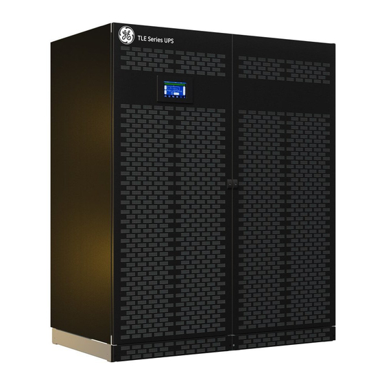
Critical Power LAYOUT LAYOUT TLE Series 160 - 220 - 225 - 250 Fig. 2.1-3 Control Panel Fig. 2.1-1 TLE Series 160 - 200 - 225 - 250 General view Fig. 2.1-4 Q1 - UPS Output switch Fig. 2.1-2 TLE Series 160 - 200 - 225 - 250 - General view with open doors Modifications reserved Page 9/91 GE_UPS_USM_TLE_SUL_M16_M50_2bU_V010.docx... -
Page 10: Layout Tle Series 300 - 400 - 500
Critical Power LAYOUT TLE Series 300 - 400 - 500 Fig. 2.2-3 Control Panel Fig. 2.2-1 TLE Series 300 – 400 - 500 - General view Fig. 2.2-4 Q1 - UPS Output switch Fig. 2.2-2 TLE Series 300 – 400 - 500 - General view with open doors Modifications reserved Page 10/91 GE_UPS_USM_TLE_SUL_M16_M50_2bU_V010.docx... -
Page 11: Introduction
RPA™ - Redundant Parallel Architecture™ Parallel System GE provides a unique technology called Redundant Parallel Architecture™ (RPA™) that can parallel Uninterruptible Power Supply (UPS) modules with true redundancy. -
Page 12: Description
With backfeed protection and compliance to EMC standards the TLE Series 160 - 500 complies to current standards. Reliability can be further increased by paralleling up to six UPS units utilizing GE’s unique RPA™ technology (Redundant Parallel Architecture). With RPA every UPS is controlled in a true peer-to-peer configuration with redundancy in all critical elements and functions, eliminating all single points of failure. -
Page 13: Block Diagram And Main Elements
Critical Power BLOCK DIAGRAM AND MAIN ELEMENTS Fig. 4.1-1 Block Diagram TLE Series 160 - 500 The TLE Series 160 - 500 system can be divided into the following main elements: Control System TLE Series 160 - 500 is designed with microprocessor-controlled signal processing circuits. The interface between the operator and the unit is provided by the monitoring system on the front panel. -
Page 14: Operation Modes
UPS control panel (see Section 6.4 / eBoost). NOTE ! The eBoost™ Operation Mode is available only if enabled at the factory or by a GE GLOBAL SERVICES FIELD ENGINEER. Modifications reserved Page 14/91 GE_UPS_USM_TLE_SUL_M16_M50_2bU_V010.docx... -
Page 15: Utility Failure Operation
Critical Power 4.2.3 Utility Failure Operation When the Utility is no longer within acceptable tolerances, the Battery will provide the DC power to the Inverter. The Inverter will maintain continuous AC power to the Load until the Battery Voltage reaches the lower limit of the Inverter operation capability. -
Page 16: Automatic Bypass
Critical Power 4.2.5 Automatic Bypass In normal operation, the Load is supplied by the Inverter. When the control system detects a fault in the Inverter, an overload condition or a short- circuit condition, the Automatic Bypass will transfer the critical Load to the Utility without interruption. -
Page 17: Rpa Parallel System Operation
Critical Power RPA PARALLEL SYSTEM OPERATION 4.3.1 Introduction to the RPA Parallel System Fig. 4.3.1-1 Block diagram RPA Parallel System operation Two or more equal power units can be paralleled to increase the output power (paralleling for capacity) or to improve the overall reliability of an UPS system (paralleling for redundancy). The outputs of parallel units are connected to a common power bus, and in normal operation the units connected on the parallel bus share the Load equally. -
Page 18: Features Of Rpa Parallel System
Critical Power 4.3.2 Features of RPA Parallel System The TLE Series 160 - 500 Parallel System is designed to provide a complete Redundant Parallel Architecture, and is free from common equipment. Not only the Inverters but also the Bypass functions are redundant. When one UPS needs maintenance or service, the Load is powered by the other units. -
Page 19: Iemi Operation Mode (Option)
Fig. 4.3.6-1 Functional diagram of a Parallel System RPA in IEMi Operation Mode GE offers the IEMi - Intelligent Energy Management integrated option to optimize energy cost while maintaining the highest possible reliability for Parallel Redundant Uninterruptible Power Supply units (max. -
Page 20: Ups Paralleled On The Same Battery
A Parallel System with a Common Battery for two or more UPS (max. 4 units), requires a particular installation and adequate setting of some parameters, (accessible only through password), and can therefore only be done by a GE QUALIFIED ENGINEER. Usually each UPS Unit runs with its own Battery. -
Page 21: Service And Technical Support
Fig. 4.5-1 Identification label WARRANTY GE, operating through its authorized agents, warrants that the standard products will be free of defects in materials and workmanship for a period as per contract specifications. NOTE ! This warranty does not cover failures of the product which result from incorrect installation, misuse, alterations by persons other than authorized agents, or abnormal working conditions. -
Page 22: Recycling Instructions
It does not contain CFCs (Carbon Fluor Clorid) or HCFCs (Halogen Carbon Fluor Clorid). PACKING MATERIAL RECYCLING GE, in compliance with environment protection, uses only environmentally friendly material. UPS packing materials must be recycled in compliance with all applicable regulations. -
Page 23: Control Panel
Critical Power CONTROL PANEL CONTROL PANEL Fig. 5.1-1 Control Panel The Control Panel, positioned on the UPS front door, acts as the UPS user interface. Main features: LCD Touch screen color graphic display. See Chapter 6. • Multilanguage communication interface: •... -
Page 24: Lcd Screen
Critical Power LCD SCREEN Composed of an LCD color “Touch Screen” which provides the following information to users: Synoptic diagram indicating UPS status. • UPS operating, AC and DC metering information. • History of events (alarms and messages). • Functionality can be programmed to meet customer needs by changing parameters. •... -
Page 25: Description Of The Selection Keys
Critical Power 6.1.1 Description of the selection keys Fig. 6.1.1-1 LCD screen Shows electric parameters values and statistics of use. MEASURES See Section 6.2. Shows in chronological order, all the events occurred (alarms, EVENTS messages, commands, handling, etc.). See Section 6.3. Allows the user to customize some UPS functions to specific SETUP requirements and to view UPS identification data. -
Page 26: Description Of The Signaling Leds
Inverter or from Automatic Bypass in case of eBoost™ Operation Mode). When blinking, indicates that a regular maintenance service is needed (SERVICE REQUIRED). May be reset by a GE Service Technicians only. See Section 9 – Maintenance – Service check. - Page 27 Critical Power LED ALARM (yellow color) It blinks when one or more alarm is activated. The internal Buzzer is ON. The LED remains blinking (with the alarm condition still present) and the buzzer stops when the key “MUTE” is pressed. The LED ALARM is also lighted when the Load is not protected by UPS or in case Q1 is open.
- Page 28 Critical Power LEDs on Synoptic Diagram LED 1 Rectifier LED 2 Inverter LED 3 Booster/Battery charger LED 4 Automatic Bypass LED 5 LOAD Examples of typical scenarios in the Synoptic Diagram: Load supplied by Inverter Load supplied by Automatic Bypass eBoost Operation Mode Load supplied by Battery IEMi Operation Mode, unit on-line...
-
Page 29: Measures
Critical Power MEASURES MEASURES The MEASURES mode is entered any time the “MEASURES” key is pressed. The LCD screen will indicate a series of screenshots showing the measures of all electric parameters like AC, DC and various statistics. In this mode the keys perform the following functions: Return to HOME screen. - Page 30 Critical Power BATTERY SCREEN Voltage The battery voltage. Current The battery current (negative values correspond to the discharge of the battery). Temperature The temperature of the battery (“XXX” indicates sensor disabled). Autonomy The estimated backup time with the present Load. Note: the backup time is computed given the unit load.
- Page 31 Critical Power BYPASS SCREEN Frequency The frequency of the input Utility. Voltage L1 / Voltage L2 / Voltage L3 3-phase Utility voltage PHASE /NEUTRAL. Current L1 / Current L2 / Current L3 Input Utility current for the 3-phases. Main failure count The total number of minor Utility faults (Bypass Utility out of tolerance faults).
- Page 32 Critical Power LOAD SCREEN Voltage L1 / L2 / L3 Output voltage PHASE/NEUTRAL for each phase. Current L1 / L2 / L3 The output current as RMS values for each phase. Percent load L1 / L2 / L3 The output Load as percentage for each phase.
-
Page 33: Events
See Section 6.6. Key to reset general alarm and buzzer. Shows the screen User Events. Shows the screen Service Events. Reserved for the GE Service Center. Shows the previous 50 events. Shows the previous 5 events. Shows the next 5 events. - Page 34 Data (MM/DD/YYYY). Exact hour of the moment when the event occurred (HH/MM/SS/ thousandth). Number of standard GE code of the event. Explicit text describing the event in the selected language. SCREEN SERVICE LOG Service Log Chronologically view 5 events per screenshot with service related info.
-
Page 35: Events (Alarms And Messages)
Each of the following listed events, alarm or message, can be displayed on the LCD screen, on a PC with the software “GE Data Protection” installed or with the monitoring system “GE iUPSGuard”. Alarms and Messages are differently specified because the alarms are indicating an abnormal... - Page 36 Critical Power Code Alarm Description This function, when enabled on input programmable relays (password required), warns the user about the 4104 BATTERY FUSES FAILURE external Battery Fuses failure or MCB opening. Signaled by NO free contact. Temperature sensor indicates a situation of overtemperature on the Rectifier bridge.
- Page 37 Critical Power Code Alarm Description Detection maximum current BOOSTER/BATTERY CHARGER booster/battery charger. 4143 CURRENT MAX The Booster/Battery charger and Inverter will switch off for protection purposes. The Booster’s driver indicates the presence of a 4146 4TH LEG DRIVER FAILURE defect which switches the power off. The Battery charger driver indicates a defect, 4147 BATTERY CHARGER DRIVER FAILURE...
- Page 38 K6 for 4406 SSM FAILURE 10 seconds. After 3 times K6 remains definitively open. Only a GE Service Technician can reset the alarm. The Utility Bypass Voltage is out of the tolerances (± 10%). 4410 BYPASS UTILITY OUT OF TOLERANCE K6 opens, synchronization with Utility is inhibited and transfer to Utility is blocked.
- Page 39 Description Detection of Battery overtemperature condition. 4697 BATTERY OVERTEMPERATURE Only a GE Service Technician can reset the alarm. In case of Utility Failure, with the actual Load, the 4698 BATTERY POWER INSUFFICIENT run time would be below stop operation time (default 3 minutes).
-
Page 40: Messages List
Critical Power 6.3.3 Messages list Code Message Description The microprocessor has detected an incorrect operation: Transfers the load on utility and performs a 4002 WATCHDOG RESET program reset. The Inverter will restart automatically and will supply the load. The voltage/current reading were not correctly 4003 SENSOR AUTO-CALIBRATION ERROR calibrated when the UPS was switched on. - Page 41 Critical Power Code Message Description Inverter cannot be switched OFF, because the 4303 INVERTER CANNOT BE TURNED OFF Load cannot be switched to Utility (voltage out of tolerance, not synchronized, BP blocked). The command to start the Inverter has been 4361 INVERTER ON activated on the control panel.
- Page 42 Critical Power Code Message Description The IEMi Operation Mode function is enabled, and 4604 COMMAND IEMi ON according to the time program the UPS system will run in IEMi Operation Mode. The IEMi Operation Mode has been disabled or the 4605 COMMAND IEMi OFF programmed time is expired.
-
Page 43: Setup
See Section 6.6. Key to reset general alarm and buzzer. Shows the screen User. Shows the screen Service Basic. Reserved for the GE Service Center, at this level the parameters access is protected by a code Shows the screen Service Full. - Page 44 Critical Power PRINTER SCREEN The UPS is capable of communicating to a serial printer, to printout disparate information. Please be sure to have a serial printer with a serial RS232 interface. This only printer-interface supported by the UPS. Baudrate This parameter controls the baud rate used for data transmission.
- Page 45 Critical Power eBOOST SCREEN (option) This screen is displayed only when eBoost™ Operation Mode is available (option). Enabled This parameter (values Yes/No) enables or disables the eBoost™ Operation Mode. If the value is “Yes” and the current time is in the interval for the current day, the eBoost™...
- Page 46 Critical Power HOURS/DAY The number of eBoost™ Operation Mode hours per weekday “Monday to Sunday” is displayed in the operation mode parameter window (ceiling value). NOTE ! To avoid undesired eBoost™ Operation Mode, verify: • Date and Time. • eBoost™ screen how many hours of eBoost™ Operation Mode have been selected for each day of the week.
- Page 47 Critical Power IEMi SCREEN (option) This screen is displayed only when IEMi Operation Mode is available (option). Enabled This parameter (values Yes/No) enables or disables the IEMi Operation Mode. If the value is “Yes” and the current time is in the interval for the current day, the IEMi Operation Mode.
- Page 48 Critical Power HOURS/DAY The number of IEMi Operation Mode hours per weekday “Monday to Sunday” is displayed in the operation mode parameter window (ceiling value). NOTE ! To avoid undesired IEMi Operation Mode, verify: • Date and Time. • IEMi screen how many hours of IEMi Operation Mode have been selected for each day of the week.
-
Page 49: Commands
Critical Power COMMANDS COMMANDS The COMMANDS mode is entered any time the “COMMANDS” key is pressed. Allows the user to execute UPS operation commands. In this mode the keys perform the following functions: Shows the main screen MEASURES. See Section 6.2. Shows the main screen EVENTS. - Page 50 Rectifier Rectifier ON Rectifier switching ON command. Rectifier RESET Rectifier restore command. Reserved for the GE Service Center. Led Rectifier status Indicates the Rectifier’s status: ON = lit OFF = turned Off Inverter Inverter ON Inverter switching ON command.
- Page 51 Parallel Bus (“Q1 – UPS Output switch” closed). Led System shutdown status Shows the “System shutdown” status: ACTIVE / NOT ACTIVE Booster Only for GE Service Center. Modifications reserved Page 51/91 GE_UPS_USM_TLE_SUL_M16_M50_2bU_V010.docx User Manual TLE Series 160 - 500 UL S2B...
- Page 52 Critical Power COMMANDS 2 SCREEN Allows the user to execute UPS operation commands. Buzzer TEST Acoustical alarm test (acoustical alarm should be always activated). Module shutdown procedure Guides throught the procedures to shutdown a single UPS or a RPA Parallel System unit. Attention: For a single UPS this implies the load disconnection.
-
Page 53: Rpa Parallel System
Critical Power RPA PARALLEL SYSTEM PARALLEL SYSTEM (option) The RPA PARALLEL SYSTEM is entered any time the “RPA” key is pressed. This screen is only displayed when the RPA Parallel System is available (option). The LCD screen will provide some information on the RPA Parallel System. - Page 54 Critical Power Description of the RPA Parallel System screen’s main elements RECT Rectifier green color = On grey color = Off CHRG / BST Battery Charger / Booster green color = On grey color = Off Inverter green color = On grey color = Off Automatic Bypass green color = On...
-
Page 55: Operation
If you encounter any problems during the following procedures, you should not continue, but contact your GE Service Center. This symbol refers to the operations of a RPA Parallel System. -
Page 56: Procedures For Single Tle Series 160 - 500
“OK”. Commissioning cannot be continued should one or more tests result to be negative. Please contact in this case your GE Service Center. At this stage the Electronic Power Supply and Control Panel are switched ON and the Buzzer sounds. - Page 57 Without such configuration it is not possible to continue with the commissioning procedure. WARNING The set-up of the UPS configuration parameters must be done only by a GE Service Technician The set-up of mistaken values could compromise the integrity and reliability of the...
- Page 58 Critical Power BATTERY Capacity Ah capacity of the Battery. Recharge Mode Recharge type of the Battery Normal Valve Regulated Lead Acid Battery (VRLA), NiCd without boost-charge and Flooded Lead Acid Battery without boost-charge. NiCd Nickel Cadmium Battery with boost-charge. Wet Lead Acid Boost Flooded Lead Acid Battery with boost-charge.
- Page 59 Critical Power 2. Close “Q1 - UPS Output switch” (Pos. I). • The Load is supplied by the Utility through the Automatic Bypass. • Rectifier starts automatically. LED 1 (Rectifier) blinking, indicates Soft-start. • At the end of Rectifier Soft-start the LED 1 (Rectifier) remains lit. The Synoptic Diagram must display the status “LOAD SUPPLIED BY AUTOMATIC BYPASS”.
-
Page 60: Complete Ups Shut-Down
Critical Power 7.1.2 Complete UPS shut-down NOTE ! Follow this procedure only in case the UPS system and the Load must be completely powered-down. If eBoost™ option is available, make sure that eBoost™ Operation Mode is disabled before starting this procedure. Initial status: Load supplied from Inverter. -
Page 61: Restore To Normal Operation After "System Shutdown" With Load Not Supplied
Critical Power 7.1.3 Restore to normal operation after “System shutdown” with Load not supplied WARNING ! Please check and ensure the conditions of the connected load are safe before proceeding, as this procedure will result in the connection of power to the load circuit(s). - Page 62 Critical Power NOTE ! Ensure the LED 1 (Rectifier) is lit before carrying out this procedure. It indicates that the DC-link 1 and DC-link 2 has reached 400Vdc (see screen MEASURES / Rectifier)! 2. Connect the Battery to the UPS by closing the “External Battery Protections”...
-
Page 63: Restore To Normal Operation After "Epo - Emergency Power Off" With Load Not Supplied
Critical Power 7.1.4 Restore to normal operation after “EPO - Emergency Power Off” with Load not supplied WARNING ! Please check and ensure the conditions of the connected load are safe before proceeding, as this procedure will result in the connection of power to the load circuit(s). - Page 64 Critical Power NOTE ! Ensure the LED 1 (Rectifier) is lit before carrying out this procedure. It indicates that the DC-link 1 and DC-link 2 has reached 400Vdc (see screen MEASURES / Rectifier)! 3. Connect the Battery to the UPS by closing the “External Battery Protections”...
-
Page 65: Procedures Single Tle Series 160 - 500 Functioning As Frequency Converter
“OK”. Commissioning cannot be continued should one or more tests result to be negative. Please contact in this case your GE Service Center. At this stage the Electronic Power Supply and Control Panel are switched ON and the Buzzer sounds. - Page 66 Without such configuration it is not possible to continue with the commissioning procedure. WARNING The set-up of the UPS configuration parameters must be done only by a GE Service Technician The set-up of mistaken values could compromise the integrity and reliability of the...
- Page 67 Critical Power BATTERY Capacity Ah capacity of the Battery. Recharge Mode Recharge type of the Battery Normal Valve Regulated Lead Acid Battery (VRLA), NiCd without boost-charge and Flooded Lead Acid Battery without boost-charge. NiCd Nickel Cadmium Battery with boost-charge. Wet Lead Acid Boost Flooded Lead Acid Battery with boost-charge.
- Page 68 Critical Power 2. Close “Q1 - UPS Output switch” (Pos. I). • Rectifier starts automatically. LED 1 (Rectifier) blinking, indicates Soft-start. • At the end of Rectifier Soft-start the LED 1 (Rectifier) remains lit. NOTE ! Ensure the LED 1 (Rectifier) is lit before carrying out this procedure. (see screen MEASURES / It indicates that the DC-link 1 and DC-link 2 has reached 400Vdc Rectifier)!
-
Page 69: Complete Shut-Down Of The Tle Series 160 - 500 As Frequency Converter
Critical Power 7.2.2 Complete shut-down of the TLE Series 160 - 500 as frequency converter NOTE ! Follow this procedure only in case the UPS system and the Load must be completely powered-down. Initial status: Load supplied from Inverter. 1. Perform the command “System shutdown”. Perform the command “System shutdown”... -
Page 70: Restore To Normal Operation After "System Shutdown" With Load Not Supplied
Critical Power 7.2.3 Restore to normal operation after “System shutdown” with Load not supplied WARNING ! Please check and ensure the conditions of the connected load are safe before proceeding, as this procedure will result in the connection of power to the load circuit(s). - Page 71 Critical Power 3. Insert the Inverter performing the command “Inverter ON". Perform the “Inverter ON” command from the screen: Commands 1 / Inverter / ON. • Soft-start of Inverter indicated with blinking LED 2 (Inverter). • At the end of Soft-start the LED 2 (Inverter) remains lit. •...
-
Page 72: Restore To Normal Operation After "Epo - Emergency Power Off" With Load Not Supplied
Critical Power 7.2.4 Restore to normal operation after “EPO - Emergency Power Off” with Load not supplied WARNING ! Please check and ensure the conditions of the connected load are safe before proceeding, as this procedure will result in the connection of power to the load circuit(s). - Page 73 Critical Power NOTE ! Ensure the LED 1 (Rectifier) is lit before carrying out this procedure. It indicates that the DC-link 1 and DC-link 2 has reached 400Vdc (see screen MEASURES / Rectifier)! 3. Connect the Battery to the UPS by closing the “External Battery Protections”...
-
Page 74: Procedures For Tle Series 160 - 500 Parallel System
“OK”. Commissioning cannot be continued should one or more tests result to be negative. Please contact in this case your GE Service Center. At this stage the Electronic Power Supply and Control Panel are switched ON and the Buzzer sounds. - Page 75 Without such configuration it is not possible to continue with the commissioning procedure. WARNING The set-up of the UPS configuration parameters must be done only by a GE Service Technician The set-up of mistaken values could compromise the integrity and reliability of the...
- Page 76 Critical Power BATTERY Capacity Ah capacity of the Battery. Recharge Mode Recharge type of the Battery Normal Valve Regulated Lead Acid Battery (VRLA), NiCd without boost-charge and Flooded Lead Acid Battery without boost-charge. NiCd Nickel Cadmium Battery with boost-charge. Wet Lead Acid Boost Flooded Lead Acid Battery with boost-charge.
- Page 77 Critical Power 2. Close “Q1 - UPS Output switch” (Pos. I) on all Units. • When closing “Q1 - UPS Output switch” on the last unit of the Parallel System, the Automatic Bypass of all Units connects to the Load. •...
- Page 78 Critical Power 5. Insert the Inverter performing the “Inverter ON” command on all other units. Do not start the next Inverter until the sequence of the previous ends. Perform the “Inverter ON” command from the screen: Commands 1 / INVERTER / ON. •...
-
Page 79: Separate A Ups Unit From The Redundant Parallel System
Critical Power 7.3.2 Separate a UPS unit from the Redundant Parallel System NOTE ! If eBoost™ option is available, make sure that eBoost™ Operation Mode is disabled before starting this procedure. If IEMi option is available, make sure that IEMi Operation Mode is disabled before starting this procedure. - Page 80 It will take 5 minutes for the DC capacitors to discharge. Open only the front door, do not open any other part of the UPS. NOTE ! For any further intervention contact nearest GE Service Center. Modifications reserved Page 80/91 GE_UPS_USM_TLE_SUL_M16_M50_2bU_V010.docx...
-
Page 81: Reconnect A Ups Unit To Redundant Parallel System
Critical Power 7.3.3 Reconnect a UPS unit to Redundant Parallel System NOTE: The Load is still powered by the other units supplying the parallel bus. This UPS unit will be powered on and connected to the parallel bus in order to share the Load with each other's. - Page 82 Critical Power NOTE ! Ensure the LED 1 (Rectifier) is lit before carrying out this procedure. (see screen MEASURES It indicates that the DC-link 1 and DC-link 2 has reached 400Vdc / Rectifier)! Before performing the next procedure (4) make sure that the LED 3 (Booster/Battery charger) is lit.
-
Page 83: Complete Parallel System Shut-Down
Critical Power 7.3.4 Complete Parallel System shut-down NOTE ! The UPS Parallel System and the Load have to be completely powered down. If eBoost™ option is available, make sure that eBoost™ Operation Mode is disabled before starting this procedure. If IEMi option is available, make sure that IEMi Operation Mode is disabled before starting this procedure. -
Page 84: Restore To Normal Operation After "System Shutdown" With Load Not Supplied
Critical Power 7.3.5 Restore to normal operation after “System shutdown” with Load not supplied WARNING ! Please check and ensure the conditions of the connected load are safe before proceeding, as this procedure will result in the connection of power to the load circuit(s). - Page 85 Critical Power NOTE ! Ensure the LED 1 (Rectifier) is lit before carrying out this procedure. It indicates that the DC-link 1 and DC-link 2 has reached 400Vdc (see screen MEASURES / Rectifier)! 2. Connect the Battery on all Units by closing the “External Battery Protections”...
-
Page 86: Restore To Normal Operation After "Epo - Emergency Power Off" With Load Not Supplied
Critical Power 7.3.6 Restore to normal operation after “EPO - Emergency Power Off” with Load not supplied WARNING ! Please check and ensure the conditions of the connected load are safe before proceeding, as this procedure will result in the connection of power to the load circuit(s). - Page 87 Critical Power NOTE ! Ensure the LED 1 (Rectifier) is lit before carrying out this procedure. It indicates that the DC-link 1 and DC-link 2 has reached 400Vdc (see screen MEASURES / Rectifier)! 3. Connect the Battery on all Units by closing the “External Battery Protections”...
-
Page 88: Options
GE Single MIB; GE Parallel MIB). The UPS can therefore be managed by a Network Management System (NMS) or by our applications (for instance GE iUPSGuard or GE Data Protection), which uses this information to determine the state of the UPS in order to guarantee safe and orderly shut-down of the server, when needed. -
Page 89: Maintenance
A UPS system, like other electrical equipment, needs periodic preventive maintenance. A regular maintenance check of your installation guarantees higher reliability of your safe power supply. GE recommends to perform the first service within 12 months from the commissioning date or within 18 months from delivery date. -
Page 90: Battery
Overall performance test including a Utility Failure simulation with and without the Load. Monitoring Battery operation in discharge and recharge mode including any boost charge duties. NOTE ! Ask to your local GE Service Center to submit the form of Preventive Maintenance Contract suitable for your specific needs. Modifications reserved Page 90/91 GE_UPS_USM_TLE_SUL_M16_M50_2bU_V010.docx... -
Page 91: Notes
Critical Power 10 NOTES 10.1 NOTES FORM It is recommended to note in this section Notes, with date and short description all the operations performed on the UPS, as: maintenance, components replacement, abnormal situations, etc. Date Description Done by Modifications reserved Page 91/91 GE_UPS_USM_TLE_SUL_M16_M50_2bU_V010.docx User Manual TLE Series 160 - 500 UL S2B...
Need help?
Do you have a question about the TLE 160 and is the answer not in the manual?
Questions and answers