Table of Contents
Advertisement
Quick Links
Advertisement
Chapters
Table of Contents
Troubleshooting

Related Manuals for Beta RR 250 2T EUROPA 2019


Summary of Contents for Beta RR 250 2T EUROPA 2019
- Page 1 STANDARD EDITION...
- Page 2 Thank you for choosing Beta as your next Motorcycle! All of us at Beta USA would like to say Thank You for your purchase and we hope you will enjoy many years of fun and excitement with your new Beta.
- Page 3 RR 250 2T EUROPA - RR 3002T EUROPA RR 250 2T - RR 3002T Thanks for you preference, and have a good time! This hand- book contains the information you need to properly operate and maintain your motorcycle. The data, specifications and images shown in this manual does not constitute an engagement on the part of BETAMOTOR S.p.A.
- Page 4 IMPORTANT We recommend you to check all the tightenings after the first one or two hours’ ride over rough ground. Special attention should be paid to the following parts: rear sprocket ensure that the footrests are properly fixed front/rear brake levers/calipers/discs check that the plastics are properly fastened engine bolts shock absorber bolts/swingarm...
-
Page 5: Table Of Contents
CONTENTS Operating instructions ................5 Symbols ....................5 Riding safety ..................6 CHAPTER 1 GENERAL INFORMATION ..........7 Vehicle identification data ............... 8 Tools kit ....................8 Familiarizing with the vehicle..............10 Specifications ..................11 Electrical system ................... 14 Recommended lubricants and liquid ............16 CHAPTER 2 OPERATION .............. - Page 6 Carburettor ..................56 Front brake..................58 Rear brake ..................61 Clutch control ..................64 Check and adjusting of steering play ............66 Fork ....................67 Front wheel ..................67 Tyres....................68 Rear suspension leverage ..............68 Chain ....................69 Headlight .................... 71 Replacing the headlight bulbs ..............
-
Page 7: Operating Instructions
OPERATING INSTRUCTIONS The vehicle must be accompanied by: number-plate, registration document, tax disc and insurance. Any modifications of the engine or other parts are punishable by severe sanctions including the confiscation of the vehicle. To protect your safety and that of others, always drive carefully and with your helmet on and always keep low beams on. -
Page 8: Riding Safety
RIDING SAFETY Observe the Highway Code. Always wear approved personal protective equipment. Always keep the crash helmet visor clean. Do not keep sharp or brittle objects in your pockets while riding. Properly adjust the rearview mirrors. Always ride in a seated position, with both hands on the handlebars and both feet on the footrests. -
Page 9: Chapter 1 General Information
CHAPTER 1 GENERAL INFORMATION CONTENTS Vehicle identification data ............... 8 Frame identification ................8 Engine identification ................8 Tools kit ....................8 Familiarizing with the vehicle..............10 Main parts: ..................10 Specifications ..................11 Weight ................... 11 Dimensions ..................11 Tyres .................... -
Page 10: Vehicle Identification Data
VEHICLE IDENTIFICATION DATA FRAME IDENTIFICATION Frame identification data A are stamped on the right side of the steering head tube. ENGINE IDENTIFICATION Engine identification data B are stamped in the area shown in the figure. TOOLS KIT The following items are supplied as stand- ard: operation, maintenance manual, tool kit and the cable adapter to connect the CAN socket to a scantool (see photo). - Page 11 The hex key 1 and its socket wrench (8 mm) are found inside the battery compart- ment. Remove the seat to reach them (page 82).
-
Page 12: Familiarizing With The Vehicle
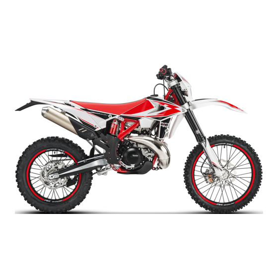
FAMILIARIZING WITH THE VEHICLE MAIN PARTS: 10 - Lower bumper 17 - Rear side panel 1 - Fuel tank (Bumper kit) 18 - Fork covers 2 - Tank cap 11 - Saddle 19 - Rear mudguard 3 - Silencer 12 - Engine 20 - Kickstarter 4 - Rear shock absorber 13 - Front mudguard... -
Page 13: Specifications
SPECIFICATIONS WEIGHT Weight in running order with full fuel and optional .............. 118 kg (front 57 Kg; rear 61 Kg) DIMENSIONS maximum length (with plate holder) ..........2270 mm maximum width ................807 mm overall height ................1270 mm wheelbase................. 1482 mm saddle height ................ -
Page 14: Front Suspension
FRONT SUSPENSION Open cartridge hydraulic upside-down fork (Ø48 mm shafts) spring ..................... K 4,2 oil type ................FUCHS SAE 5W oil quantity ..................510 g wheel excursion ................290 mm compression clicks (from completely closed) ..........12 rebound clicks (from completely closed) ..........12 sping preload clicks (from completely open) .......... - Page 15 Carburetor RR 250 Europe RR 250 RR 300 Europe RR 300 Version Main jet Slow jet Start jet Needle N84K N0ZJ N84K N2ZW Needle position (from top) 2° 3° 2° 2° Air screw turns (from all closed) 1+1/2 1+1/4 1+1/4 Cooling system .........
-
Page 16: Electrical System
ELECTRICAL SYSTEM ELECTRICAL DIAGRAM Key to colours Bi = White Ve = Green Ma = Brown Vi = Purple Bl = Blue Ne = Black Gi = Yellow Rs = Red Ar = Orange Az = Sky-blue Ro = Pink Gr = Grey... -
Page 17: Legend Electrical Diagram
LEGEND ELECTRICAL DIAGRAM RIGHT-HAND FRONT TURN INDICATOR 12V 6W FRONT BRAKE LIGHT BUTTON ENGINE STOP BUTTON START BUTTON SECOND MAP SWITCH (OPTIONAL) WHEEL REVOLUTION SENSOR TURN INDICATORS WARNING LIGHT RIGHT BUTTON OIL RESERVE WARNING LIGHT DASHBOARD HEADLIGHT TELL TALE LAMP LEFT BUTTON MIXER DIAGNOSIS WARNING LIGHT HORN BUTTON... -
Page 18: Recommended Lubricants And Liquid
RECOMMENDED LUBRICANTS AND LIQUID To maximize the vehicle’s performance and ensure many years of trouble-free opera- tion, we recommend using the following products: PRODUCT TYPE SPECIFICATIONS Injection Oil Motul 710 Motul Trasoil Expert 10W40 Transmission Oil Brake Fluid Motul RBF 600 Coolant/Antifreeze Motul Motocool Expert Fork Oil... -
Page 19: Chapter 2 Operation
CHAPTER 2 OPERATION CONTENTS Main parts ..................18 Fuel tank cap .................. 18 Fuel cock ..................18 Starter .................... 19 Mixer oil tank cap ................19 Clutch lever ..................19 LH switch ..................20 RH switch ..................20 Front brake lever and gas control ............20 Gear change lever................ -
Page 20: Main Parts
MAIN PARTS FUEL TANK CAP Use unleaded petrol (gasoline). Disconnect the ventilation pipe 1. To open the tank turn the cap 2 anticlock- wise. To close the fuel tank’s cap, set it on the tank and crew it clockwise. FUEL COCK Fuel cock has three positions: OFF: fuel supply closed. -
Page 21: Starter
STARTER The starter lever is located on the carbu- rettor. To operate the choke pull it upward. MIXER OIL TANK CAP The mixer oil tank cap is located under the saddle To gain access remove the saddle (page 82). To open the fuel tank cap turn it anticlock- wise. -
Page 22: Lh Switch
LH SWITCH The dip and service switch is located on the left side of the handlebar and is com- posed as follows: 1 - Horn button; 2 - Dip switch: parking lights and high beam; parking lights and low beam; 3 - Flash-to-pass button;... -
Page 23: Gear Change Lever
GEAR CHANGE LEVER Gear change lever is fitted to the left side of the engine. The positions corresponding to the different gears are shown in the figure. BRAKE PEDAL Brake pedal is located in front of the right- hand footrest. The rear brake is operated by pressing down the pedal. -
Page 24: Keys
If the vehicle is used off-road, the closed stand can be further fastened by means of rubber band. KEYS The vehicle is supplied with two keys (one key and its spare). STEERING LOCK To activate the steering lock: - turn the handlebar counter-clockwise; - push the key and turn counter-clockwise;... -
Page 25: Digital Rpm Indicator Operating Instructions
DIGITAL RPM INDICATOR OPERATING INSTRUCTIONS Index General information Operating condition General characteristics Dashboard start-up process 3.1.1 Wake up events LCD Display 3.2.1 LCD general characteristics 3.2.2 Speed 3.2.3 Odometer 3.2.4 Trip A 3.2.5 Trip B 3.2.6 Clock 3.2.7 Ride Time 3.2.8 Unit option display 3.2.9... - Page 26 3 GENERAL CHARACTERISTICS 3.1 DASHBOARD START-UP PROCESS The dashboard do some start-up process when is turned ON. There are three differ- ent wakes up events for starting the dashboard. This start-up process consists in turning ON the telltales and the LCD backlight and the LCD will show all the segments during 2 seconds.
- Page 27 3.2.1 LCD GENERAL CHARACTERISTICS Each information/data is refreshed independently at different rates, depending on information type and variability of this information. 3.2.2 SPEED Dashboard computes and displays the motorbike speed on LCD display. Speed information can be obtained from: Dedicated digital input for measuring speed sensor frequency. 3.2.2.1 Speed digital input configuration Configuration parameters for speed input and speed visualization.
- Page 28 3.2.3 ODOMETER Dashboard provides an odometer and is displayed on LCD display. This option can be displayed scrolling by “MODE” button. 6 digits and “ODO” icon lighted. Leading zeros not suppressed. Display range from 000000 to 999999 km or miles. If odometer is greater than 999999 km, odometer will be fixed as 999999km.
- Page 29 3.2.5 TRIP B This option can be displayed scrolling by “MODE” dashboard button. 4 digits (3digits + decimal point + 1 digit), “TRIP” icon lighted and “B” on the left. Leading zeros suppressed. Display range from 0.0 to 999.9 km or miles. Trip B counter counts from 0 up to 999.9 and then rolls over to 0 and continue counting.
- Page 30 3.2.7 RIDE TIME Dashboard provides a Ride Time and is displayed on LCD display. Time is obtained from internal crystal quartz and is kept with a push buttons. When the motorbike is turned on the ride time starts again. 3.2.8 UNIT OPTION DISPLAY Dashboard provides the possibility to change the units and be displayed.
- Page 31 3.2.10 MOTORBIKE BATTERY LEVEL Dashboard displays level of voltage of battery power supply: Relationship between bars and level of voltage: Bars Voltage [V] Bars Voltage [V] 11.5 13.5 12.5 14.5 Battery level is updated every 30 seconds. Each update increase or decrease 1 bar. WARNING If the word “HIGH”...
- Page 32 Mode Speed Function Button Time (sec) Activity CLOCK “On Entering MODE <2 Increase in the Hour digits MODE Stop Clock Mode“ MODE >2 Speedy increase in the Hour digits <2 Increase in the minutes digits >2 Speedy increase in the minutes digits MODE&SET >2 Exit clock set mode and save the value...
- Page 33 3.3 TELLTALES LED number indicator: LED 1 LED 2 LED 3 LED 4 Telltales/Indicator lights specifications: Number of telltales: 4 LED number Function Symbol LED 1 Blinkers LED 2 High beam LED 3 Oil Reserve MIL telltale (Engine management LED 4 system fault)
- Page 34 Power +12V are provided to the dashboard only when the bike is turned on (regulator line). Blinkers LED The system activates the indicator in synchrony with the activation of the direction indicators High beam LED The system activates the indicator in synchrony with the activation of the high beam. Oil reserve LED MIL LED Indicates a fault in the engine management system.
-
Page 35: Checks Before And After Use
CHECKS BEFORE AND AFTER USE For safe driving and long vehicle life you should: 1 Check the integrity of the oil pipe connecting the intake manifold to the electronic dosing. 2 Check all fluid levels. 3 Check the correct operation of the brakes and brake pad wear (page 60). 4 Check pressure, general condition and thickness of tread (page 68). -
Page 36: Refuelling
REFUELLING See page 16 for the fuel specifications. . Fuel tank capacity is shown on page 11. To refuel open the tank cap (page 18). After refuelling, screw the cap back and tighten securely. WARNING The refuelling should be performed with the engine off. WARNING Fire hazard. -
Page 37: Starting The Engine
STARTING THE ENGINE Move the fuel tank valve in ON or RES position (page 18). Check that the gears are in neutral (page 21). Pull the clutch lever (page 19). Close the side stand (page 21). WHIT ELECTRIC STARTER (page 20): Press the startup button for a max of 3 seconds. -
Page 39: Chapter 3 Adjustments
CHAPTER 3 ADJUSTMENTS CONTENTS Key to symbols..................38 Brakes ....................38 Front brake ..................38 Rear brake ..................38 Clutch ....................38 Adjustment of gas clearance ..............39 Adjusting the idle speed ................ 39 Carburetor settings according to the working conditions ....... 40 Exhaust valve control adjustment ............ -
Page 40: Key To Symbols
KEY TO SYMBOLS Tightening torque Threadlocker Medium Grease BRAKES FRONT BRAKE The front brake is disk type with hydraulic control. The home position of brake lever 2 can be adjusted by means of screw 1. REAR BRAKE The home position of brake pedal 3 can be altered by turning adjusting screw 5 af- ter loosening the counternut located under dust cap 4. -
Page 41: Adjustment Of Gas Clearance
ADJUSTMENT OF GAS CLEARANCE The throttle control cable should always have a 3-5 mm play. In addition, the idle speed should not change when the han- dlebars are fully rotated to the left or right. Push back protective cap 1. Loosen coun- ternut 2 and turn adjusting screw 3. -
Page 42: Carburetor Settings According To The Working Conditions
To properly adjust the idle speed, follow these steps: Tighten the air adjustment screw no. 2 fully and then loosen it up to the value described in the carburetor setting table (page 13) 2 clockwise, until idling starts diminishing. 2 counterclockwise, until idling decreases again. - Page 43 Version RR 250 Altitude Carburetor Ambient temperature (SLM) setting -20°C÷ -6°C÷ 6°C ÷ 16°C ÷ 25°C ÷ 37°C ÷ ÷-7°C 5°C 15°C 24°C 36°C 49°C -2°F ÷ 19°F ÷ 42°F ÷ 61°F ÷ 79°F ÷ 99°F ÷ 20°F 41°F 60°F 78°F 98°F 120°F...
- Page 44 Version RR 300 Altitude Carburetor Ambient temperature (SLM) setting -20°C -6°C÷ 6°C ÷ 16°C ÷ 25°C ÷ 37°C ÷ ÷-7°C 5°C 15°C 24°C 36°C 49°C -2°F ÷ 19°F ÷ 42°F ÷ 61°F ÷ 79°F ÷ 99°F ÷ 20°F 41°F 60°F 78°F 98°F 120°F...
-
Page 45: Exhaust Valve Control Adjustment
EXHAUST VALVE CONTROL ADJUSTMENT increases HANDLEBAR ADJUSTMENT U-BOLT POSITION ADJUSTMENT The lower bracket 1 can be mounted in correspondence of the holes nr. 2, 3 or 4 respectively. To adjust the position of the u-bolt remove the screws shown in the figure. Remove the handlebar. -
Page 46: Adjusting Fork
Apply the handlebar. Apply the top u-bolt. Refit the screws 6. Tighten to the torque indicated. 25Nm ADJUSTMENT OF THE HANDLEBAR POSITION The handlebar can be adjusted by rotating it back and forth. To adjust the handlebar loosen screws 1. Position the handlebar according to re- quirements. -
Page 47: Shock Absorber
ADJUSTING THE SPRING PRELOAD The spring preload is adjusted by using the ring nut B. Rotate clockwise to increase the spring preload or anticlockwise to decrease it. The spring preload varies by one millim- eter, each complete revolution. ADJUSTING THE COMPRESSION DAMPER The hydraulic compression damper deter- mines the behaviour of the telescopic fork... -
Page 48: Adjusting The Spring Preload
ADJUSTING THE HYDRAULIC COMPRESSION DAMPER (HIGH AND LOW SPEEDS) Adjustment for low compression speed: Using a screwdriver, loosen screw C by turning it clockwise to increase the hydraulic compression damper. For standard setting, refer to page 12. Adjustment for high compression speed: Turn knob D anticlockwise to decrease the hydraulic compression damper. -
Page 49: Static Sag Load Test
STATIC SAG LOAD TEST To verify the static sag of the shock ab- sorber proceed as follows: - Place the motorcycle on the work stand. - Measure the vertical distance between the rear wheel axle and a reference point on the rear fairings. - Write down the dimension H - Remove the work stand. -
Page 51: Chapter 4 Checks And Maintenance
CHAPTER 4 CHECKS AND MAINTENANCE CONTENTS Key to symbols...................50 Engine oil ....................50 Check the level ..................50 Replacement ..................50 Liquid coolant ....................51 Check the level ..................51 Replacement ..................52 Air filter ....................54 Removing and installing air filter .............54 Air filter cleaning - RR 250/300 Europa ..........55 Air filter cleaning - RR 250/300 .............55 Spark plug ....................55 Carburettor ....................56... -
Page 52: Key To Symbols
KEY TO SYMBOLS Tightening torque Threadlocker Medium Grease ENGINE OIL CHECK THE LEVEL Hold the vehicle upright. Position the drive on a flat base ensuring stability. Remove the inspection cap 1. The oil level must arrive to the lower edge of check hole. -
Page 53: Liquid Coolant
- Unscrew filler plug 1 and drain plug 2. - Drain all the oil from the crankcase. - Place the cap 2 and tighten to specified torque. Pour in the quantity of liquid indicated on page 16. Use the oil indicated on page 16 in 15Nm the “Recommended lubricants and liquids”... -
Page 54: Replacement
WARNING: Wear appropriate protective cloth- ing and protection gloves. Keep coolant out of reach of chil- dren. Avoid any direct contact of the cool- ant with skin, eyes or clothing. If this happens: - with the eyes, rinse immediately with plenty of water and seek medical advice;... - Page 55 - Unscrew drain screw 3. - Proceed to filling. - Reapply the loading cap and the bleed- ing screw. The amounts of liquid are shown on page Use the liquid indicated on a page 16 in the “Recommended lubricants and liquids”...
-
Page 56: Air Filter
filter box. NOTE: If the filter is damaged, replace it immediately. To replace, contact authorised Beta- motor customer service. WARNING: Never use the vehicle if the air filter is not in place. The infiltration of dust and dirt can cause damage and considerable wear. -
Page 57: Spark Plug
AIR FILTER CLEANING - RR 250/300 EUROPA Blow the filter with compressed air. AIR FILTER CLEANING - RR 250/300 Thoroughly wash the filter with water and soap. Dry the filter. Wet the filter with filter oil and then remove the excess oil to prevent it from drip- ping. -
Page 58: Carburettor
CARBURETTOR DRAINING THE CARBURETTOR FLOAT CHAMBER If the carburettor tank needs to be emptied, proceed as described. Remove the chain protection 1, close the tank tap and put a cloth under the carbu- rettor, so that you can collect the running out fuel. -
Page 59: Checking The Float Level
WARNING: Risk of poisoning! Fuel is poisonous liquid and a health hazard. Wear appropriate protective cloth- ing and protection gloves. Fuel must not come into contact with the skin, eyes, and clothing. Do not breathe in the fuel vapours. If contact occurs with the eyes, rinse immediately with plenty of water and seek medical advice. -
Page 60: Front Brake
FRONT BRAKE CHECK THE LEVEL OF THE FRONT BRAKE FLUID Check the level of the brake fluid through sight A. The level of the fluid should never fall below the mark in the sight. RESTORING THE LEVEL OF THE FRONT BRAKE FLUID To restore the level of the brake fluid, loosen the two screws 1, lift cap 2 and add brake fluid until its level is 5 mm below the upper... -
Page 61: Bleeding The Front Brake
BLEEDING THE FRONT BRAKE To bleed air from the front brake circuit, proceed as follows: Remove the rubber cap 1 from the valve 2. Open the sump cap. Place one end of a small transparent tube into the valve 2, and the other end inside a container. -
Page 62: Front Brake Lining Control
FRONT BRAKE LINING CONTROL In order to verify the wear condition of front brake is enough to view the caliper from the bottom, where is possible to glimpse the brake lining tails which will have to show a brake of 2 mm in thickness. If the stratum is lesser let’s start replacing them. -
Page 63: Rear Brake
REAR BRAKE CHECK THE LEVEL OF THE REAR BRAKE FLUID Check the level of the brake fluid through sight A. The level of the fluid should never fall below the mark in the sight. RESTORING THE LEVEL OF THE REAR BRAKE FLUID To restore the oil level, top up by means of oil filler cap 1. -
Page 64: Bleeding The Rear Brake
BLEEDING THE REAR BRAKE To bleed air from the rear brake circuit, proceed as follows: Remove the rubber cap 1 from the valve 2. Open the sump cap. Place one end of a small transparent tube into the valve 2, and the other end inside a container. -
Page 65: Rear Brake Lining Control
REAR BRAKE LINING CONTROL In order to verify the wear condition of rear brake is enough to view the caliper from above, where is possible to glimpse the brake lining tails which will have to show a brake of 2 mm in thickness. If the stratum is lesser let’s start replacing them. -
Page 66: Clutch Control
CLUTCH CONTROL CHECK THE LEVEL To check the oil level in the clutch pump, first remove cover 2. Remove the two screws 1 and take off cover 1 together with the rubber bellows. With the clutch pump in a horizontal posi- tion, the level of the oil should be 5 mm below the upper rim. -
Page 67: Bleeding
BLEEDING To bleed air from the clutch pump, proceed as follows: Remove the rubber cap 1 from the valve 2. Open the sump cap. Place one end of a small transparent tube into the valve 2, and the other end inside a container. -
Page 68: Check And Adjusting Of Steering Play
CHECK AND ADJUSTING OF STEERING PLAY Periodically check the play in the steering sleeve by moving the fork back and forth as shown in the figure. Whenever you feel play, adjust as described below: - Loosen the screws 1 17Nm - Loosen the screw 2 - Reduce the play by turning nut 3 Tighten the screws to the prescribed torque... -
Page 69: Fork
FORK 17Nm To maintenance refer at an authorized service centre Betamotor. To check the tightening torques see as shown in the figure. WARNING: Tightening of the screws should be carried out by adjusting the torque wrench to the stability torque with repeated tightening until stability torque has been achieved. -
Page 70: Tyres
REAR SUSPENSION 70Nm LEVERAGE In order to guarantee optimal operation and duration over time of the progressive leverage of the rear suspension, it is rec- ommended to periodically check correct tightness of nuts and bolts. Verify that suspension nuts and bolts are at the indicated torque. -
Page 71: Chain
CHAIN Checking the drive chain periodically to ensure longer chain life. Always keep it lubricated and clean of deposited dirt. Take special care in preventing the lubri- cant from coming into contact with the rear tyre or brake disc, otherwise the tyre grip and the action of the brake would be greatly reduced, making it very difficult to control the vehicle. -
Page 72: Check For Chain Wear
Loosen counternuts A on either side of the fork. Turn adjusting screws B on either side until the desired chain tension is obtained. Tighten counternuts A on either side of the fork. Tighten the pin 1 to the torque indicated. CHECK FOR CHAIN WEAR 10 -15 Kg Shift into neutral, pull up the upper stretch... -
Page 73: Headlight
HEADLIGHT Keep the headlight glass clean at all times (see page 75). Periodically check the correct angle of the light beam. REPLACING THE HEADLIGHT BULBS Remove the fixing screws and move for- ward the lamp holder front cowl. Carefully remove the headlight bulb 1 together with lamp holder. -
Page 74: Battery
BATTERY Battery is located under the saddle and requires no maintenance. Keep the battery terminals clean. If neces- sary, protect them with a thin film of acid- free grease. WARNING: The battery contains hazardous substances: - Keep the batterie out of the reach of children. - Keep sparks and open flames away from the battery. -
Page 75: Battery Assembly
THEN remove the cap of the positive pole 3 and disconnect the positive lug 4 (red) from the positive pole (+). Release the rubber band 5. Remove the battery. BATTERY ASSEMBLY When fitting the battery, insert it with the terminals as shown in picture. Reattach the rubber band 5. -
Page 76: Fuses
CHARGING THE BATTERY Check the battery charge using a multi- meter or by pressing the “TEST” button on the battery - Voltage < 9V or “LOW”: - Do NOT charge the battery - Replace the battery with a new equivalent one - Voltage <12.4V or “MED”: - Charge the battery Guidelines to charge the battery:... -
Page 77: Cleaning The Vehicle
CLEANING THE VEHICLE GENERAL PRECAUTIONS WARNING: Do not clean your vehicle with a high-pressure device with a strong jet of water. Excessive pressure can reach electrical components, con- nectors, flexible cables, bearings, etc and can damage or destroy them. WARNING: Wash motorbikes frequently with cold water that are used near the sea (salty air) and on roads subject to salt spreading in winter. -
Page 78: Prolonged Inactivity
PROLONGED INACTIVITY A few simple operations should be performed to keep the vehicle in good condition whenever it is to remain inactive for a long period (e.g. during the winter): Thoroughly clean the vehicle. Reduce the tyre pressures by approximately 30 percent, and if possible raise the tyres off the ground. -
Page 79: Scheduled Maintenance Vehicle
SCHEDULED MAINTENANCE VEHICLE Engine Gear and clutch oil Spark plug Head screws Engine clamping screws * Kick start and gearchange lever screws Spark plug cap Coated clutch disks Clutch springs length Clutch/bell hub Gearbox bearing (drive shaft side) Cylinder Piston and segments Connecting rod Drive shaft bearings Surface appearance of the gearbox... - Page 80 Brakes Liquid level, pads thickness Disc thickness Pipe tightness Idle travel levers and drives sliding Cycling Shock absorber and telescopic fork Rear suspension linkage Fuel lines Fork cover Bearings of stearing Bolts Wheels Wheel spokes and rim coaxiality Tyres (wear and pressure) Bearings clearance Check (Clean, adjust, lubricate, replace as necessary) Replace/renew...
-
Page 81: Tightening Torque Overview
TIGHTENING TORQUE OVERVIEW Here below is an overview of the tightening torque of all pieces subject to adjust- ment or maintenance: Forecarriage Tightening torque [Nm] Threadlock Wheel pin Fork foots - wheel pin Brake caliper - Fork Cavallotto parastelo sinistro Steering head base - fork legs Steering head - fork legs Stem pin on steering head... -
Page 83: Chapter 5 Removing And Installing Superstructures
CHAPTER 5 REMOVING AND INSTALLING SUPERSTRUCTURES CONTENTS Removing and installing of the saddle ............. 82 Removing and installing air filter side panel ..........83 Removing and installing of the complete tank........... 83... -
Page 84: Removing And Installing Of The Saddle
REMOVING AND INSTALLING OF THE SADDLE Press button 1. Remove the saddle towards the rear of the motorcycle. To re-assemble: Insert the cavity 1 of the saddle in slot 2. Press the saddle down in the middle and at the same time, push it forwards until the bayonet joint engages in its seat. -
Page 85: Removing And Installing Air Filter Side Panel
WARNING Make sure the bayonet joint 3 is firmly inserted into the button lock. REMOVING AND INSTALLING AIR FILTER SIDE PANEL Remove the saddle (page 82). Grab the side panel in the front side and pull out. To refit insert the tabs 1 into their slots. Slide the side panel toward the vehicle. - Page 86 Remove the air filter side panel (page 83). Remove the two screws 1 fastening the tank to the frame and the screw 2 (one per side) securing the fairing to the radiator. Lift the tank complete with side panels. Replace the previously removed compo- 10Nm nents following the disassembly procedures inversely.
-
Page 87: Chapter 6 Troubleshooting
CHAPTER 6 TROUBLESHOOTING CONTENTS Troubleshooting ................... 86 Alphabetical index ................87... -
Page 88: Troubleshooting
TROUBLESHOOTING PROBLEM CAUSE REMEDY Engine does not start -Fuel system clogged (fuel lines, fuel Contact authorised BETAMOTOR tank, fuel cock) customer service - Air filter dirty Check the air filter - No current supplied to spark plug Clean or replace the spark plug. If the problem persists, contact authorised BETAMOTOR customer service - Engine flooded... - Page 89 ALPHABETICAL INDEX Adjusting fork ..................44 Adjusting the idle speed ................ 39 Adjustment of gas clearance ..............39 Air filter ....................54 Battery ....................72 Brakes ....................38 Carburettor ..................56 Chain ....................69 Check and adjusting of steering play ............66 Checks before and after use ..............
- Page 90 Oil mixer refuelling ................34 Operating instructions ................5 Prolonged inactivity ................76 Rear brake ..................61 Rear suspension leverage ..............68 Recommended lubricants and liquid ............16 Refuelling .................... 34 Removing and installing air filter side panel ..........83 Removing and installing of the complete tank...........
- Page 91 RR 2T ENDURO 2019 250/300cc CATALOGO PARTI DI RICAMBIO CATALOG OF SPARE PARTS CATALOGUE PIECES DE RECHANGE ERSATZTEILKATALOG CATALOGO DE PIEZAS DE REPUESTO Le presenti immagini e i contenuti sono di esclusiva titolarità di Betamotor S.p.A., che si riserva tutti i relativi diritti. Non è consentita alcuna riproduzione, modifica, elaborazione, divulgazione, comunicazione, utilizzazione econo- mica in ogni forma e modo, originale o derivato, che non sia espressamente consentita per iscritto da Betamotor S.p.A.
- Page 92 TAV.01A Carter completo - Cranckcase, assy - Carter complet - Kurbelwellengehä use, TAV.01B Coperchio frizione - Clutch cover - Couvercle d'embrague - Kupplungsdeckel - KPL. - Carter completo Tapa embrague Pag. 8 Pag. 6 TAV.01C Collettore aspirazione - Intake manifold - Collecteur aspiration - Ansaugstutzen - TAV.02 Albero motore - Crankshaft - Vilebrequin - Kurbelwelle - Cigüeñal Colector aspiració...
- Page 93 TAV.10 Gruppo accensione elettronica - Electronic ignition assy. - Groupe allumage elec- TAV.11 Cilindro completo - Cylinder , assy - Cylindre complet - Zylinder, KPL. - Cilindro tronique - Elektronichezünduk gruppe - Grupo encedido electró nico completo Pag. 22 Pag. 20 TAV.12 Carburatore - Carburettor - Carburateur - Vergaser - Carburador TAV.14 Attrezzatura specifica - Special tools - Outillage spé...
- Page 94 TAV.36 Impianto freni idraulici - Hydraulic brakes system - Installation des freins TAV.37 Gruppo scarico - Exhaust system - Echappement - Auspuffanlage - Grupo escape hydrauliques - Hidraulichebremse anlage - Instalació n freno hidrá ulico Pag. 40 Pag. 42 TAV.38 Scatola filtro - Filter box - Boî tier du filtre - Sicherungskasten - Caja del filtro TAV.39 Impianto di raffreddamento - Installation de refroidissement - Installation de refroidissement - Kühlsystem - Instalació...
- Page 95 Pag.5...
- Page 96 Tav.01A Pag.6...
- Page 97 Tav.01A Numero Q.tà Nota Descrizione Description Désignation Beschreibung Descripciòn Number Q.ty Note Numéro Q.té Note Número M.ge Nota Nummer C.ad Anm. 026.01.021.80.00 Carter motore Crankcase assy Carter moteur complet Kurbekgehä use, kompl. Carter motor completo 026.01.003.00.00 Guarnizione carter Crankcase gasket Joint carter Dichtung Kurbelwellengehä...
- Page 98 Tav.01B Numero Q.tà Nota Descrizione Description Dé signation Beschreibung Descripciò n Number Q.ty Note Numé ro Q.té Note Número M.ge Nota Nummer C.ad Anm. 026.01.020.80.52 Coperchio frizione interno Inner clutch cover Couvercle interne d’ embrayage Innerer Kupplungsdeckel Tapa interior embrague 026.01.005.00.00 Guarnizione coperchio frizione Clutch cover gasket...
- Page 99 Tav.01C Numero Q.tà Nota Descrizione Description Dé signation Beschreibung Descripciò n Number Q.ty Note Numé ro Q.té Note Número M.ge Nota Nummer C.ad Anm. 15.14275.000 Fascetta 52/12 Clamp 52/12 Collier 52/12 Schelle 52/12 Abrazadera 52/12 11.50010.000 Bullone M6x25 Bolt M6x25 Boulon M6x25 Bolzen M6x25 Tornillo M6x25...
- Page 100 Tav.02 Pag.10...
- Page 101 Tav.02 Numero Q.tà Nota Descrizione Description Dé signation Beschreibung Descripciò n Number Q.ty Note Numé ro Q.té Note Número M.ge Nota Nummer C.ad Anm. 026.02.015.80.00 Albero motore completo Crankshaft, assy. Arbre moteur complet Kurbelwelle, komplett Cigüeñal completo 026.02.026.80.0A 250cc Pistone completo 250cc - Sel. A Piston set 250cc - Sel.
- Page 102 Tav.03 Pag.12...
- Page 103 Tav.03 Numero Q.tà Nota Descrizione Description Dé signation Beschreibung Descripciò n Number Q.ty Note Numé ro Q.té Note Número M.ge Nota Nummer C.ad Anm. 029.03.011.00.00 Corona trasmissione primaria Clutch case assembly Cloche d’ embrayage compl. Kupplungsglocke. Campana de embr.completa 029.03.141.00.00 Mozzo frizione Clutch drum Moyeu d’...
- Page 104 Tav.04A Numero Q.tà Nota Descrizione Description Désignation Beschreibung Descripciòn Number Q.ty Note Numéro Q.té Note Número M.ge Nota Nummer C.ad Anm. 026.04.000.80.00 Cambio completo Transmission, assy Boî te de vitesses Getriebe komplett Cambio completo 026.04.010.00.00 Albero primario completo Complete main shaft Arbre primaire complet Komplette Hauptwelle Arbol primario completo...
- Page 105 Tav.04B Numero Q.tà Nota Descrizione Description Désignation Beschreibung Descripciòn Number Q.ty Note Numéro Q.té Note Número M.ge Nota Nummer C.ad Anm. 026.04.020.00.00 Albero secondario Counter shaft Arbre secondaire Nebengetriebewelle Eje secundario 12.99710.000 Cuscinetto NJ205 Bearing NJ205 Roulement NJ205 Lager NJ205 Cojinete NJ205 10.66020.000 Anello paraolio 32x45x6x5...
- Page 106 Tav.05 Numero Q.tà Nota Descrizione Description Désignation Beschreibung Descripciòn Number Q.ty Note Numéro Q.té Note Número M.ge Nota Nummer C.ad Anm. 006.05.000.80.00 Leva comando cambio Gear change lever Levier comm. chang. vit. Schalthebel Palanca cambio 11.50010.000 Bullone M6x25 Bolt M6x25 Boulon M6x25 Bolzen M6x25 Tornillo M6x25...
- Page 107 Tav.07 Numero Q.tà Nota Descrizione Description Désignation Beschreibung Descripciòn Number Q.ty Note Numéro Q.té Note Número M.ge Nota Nummer C.ad Anm. 026.07.000.80.00 Motorino avviamento Starter motor Moteur du dé marreur Startermotor Motor de arranque 36.25056.000 Anello OR 25,00x3,00 O-Ring 25,00x3,00 Bague d’...
- Page 108 Tav.09 Pag.18...
- Page 109 Tav.09 Numero Q.tà Nota Descrizione Description Dé signation Beschreibung Descripciò n Number Q.ty Note Numé ro Q.té Note Número M.ge Nota Nummer C.ad Anm. 026.09.013.80.00 Bilanciere compl. Rocker arm assy Culbuteur compl. Kipphebel kpl. Balancí n compl. C16.02.001.00.00 Rondella 5.15.2 Washer 5.15.2 Rondelle 5.15.2 U.Scheibe 5.15.2...
- Page 110 Tav.10 Pag.20...
- Page 111 Tav.10 Numero Q.tà Nota Descrizione Description Dé signation Beschreibung Descripciò n Number Q.ty Note Numé ro Q.té Note Número M.ge Nota Nummer C.ad Anm. 026.01.051.80.52 Coperchio volano Flywheel cover Carter volant Schwungraddeckel Tapa volante 11.50010.000 Bullone M6x25 Bolt M6x25 Boulon M6x25 Bolzen M6x25 Tornillo M6x25 11.49070.000...
- Page 112 Tav.11 Pag.22...
- Page 113 Tav.11 Numero Q.tà Nota Descrizione Description Dé signation Beschreibung Descripciò n Number Q.ty Note Numé ro Q.té Note Número M.ge Nota Nummer C.ad Anm. 12.25123.000 250cc Candela Spark.plug Bougie Zündkerze Bujia 12.25220.000 300cc Candela Spark.plug Bougie Zündkerze Bujia 026.10.012.00.00 Guarnizione candela Spark plug gasket Joint bougie Zündkerzendichtring...
- Page 114 Tav.12 Pag.24...
- Page 115 Tav.12 Numero Q.tà Nota Descrizione Description Dé signation Beschreibung Descripciò n Number Q.ty Note Numé ro Q.té Note Número M.ge Nota Nummer C.ad Anm. 026.12.049.82.00 250cc Carburatore Carburettor Carburateur Vergaser Carburador 026.12.059.82.00 300cc Carburatore Carburettor Carburateur Vergaser Carburador 026.12.058.82.00 1 EU250cc Carburatore Carburettor Carburateur Vergaser...
- Page 116 Tav.14 Pag.26...
- Page 117 Tav.14 Numero Q.tà Nota Descrizione Description Dé signation Beschreibung Descripciò n Number Q.ty Note Numé ro Q.té Note Número M.ge Nota Nummer C.ad Anm. 007.14.010.80.00 Disaccoppiatore carter Crankcase splitter Sé parateur de carter Entkoppler gehä use Desacoplador del cá rter 029.14.002.50.00 Chiave speciale Special wrench...
- Page 118 Tav.31 Pag.28...
- Page 119 Tav.31 Numero Q.tà Nota Descrizione Description Dé signation Beschreibung Descripciò n Number Q.ty Note Numé ro Q.té Note Número M.ge Nota Nummer C.ad Anm. 026.31.082.80.50 Telaio completo Frame, assy Chassis complet Rahmen, kpl Bastidor compl. 12.99510.000 Cuscinetto conico 29x50x15 Conical bearing 29x50x15 Roulement conique 29x50x15 Lager 29x50x15 Cojinete conico 29x50x15...
- Page 120 Tav.32 Pag.30...
- Page 121 Tav.32 Numero Q.tà Nota Descrizione Description Dé signation Beschreibung Descripciò n Number Q.ty Note Numé ro Q.té Note Número M.ge Nota Nummer C.ad Anm. 026.32.003.82.51 Telaietto posteriore Rear frame Châ ssis arriè re Hinterer kleiner Rahmen Bastidor trasero 020.32.100.00.59 Braccetto destro Right arm Bras droit Rechter Schutzblecharm...
- Page 122 Tav.33A Pag.32...
- Page 123 Tav.33A Numero Q.tà Nota Descrizione Description Dé signation Beschreibung Descripciò n Number Q.ty Note Numé ro Q.té Note Número M.ge Nota Nummer C.ad Anm. 026.33.011.80.00 Ammortizzatore completo Shock absorber assembly Amortisseur complet Stoßdä mpfer komplett Amortiguador completo 020.33.141.00.00 Tampone Buffer Silentbloc Puffer Silent-block...
- Page 124 Tav.33B Pag.34...
- Page 125 Tav.33B Numero Q.tà Nota Descrizione Description Désignation Beschreibung Descripciòn Number Q.ty Note Numéro Q.té Note Número M.ge Nota Nummer C.ad Anm. 031.33.019.00.59 Forcellone Big fork Fourche Radschwinge Horquilla 026.33.011.80.00 Ammortizzatore completo Shock absorber assembly Amortisseur complet Stoßdä mpfer komplett Amortiguador completo 020.33.030.80.00 Bielletta Connecting rod...
- Page 126 Tav.34 Pag.36...
- Page 127 Tav.34 Numero Q.tà Nota Descrizione Description Dé signation Beschreibung Descripciò n Number Q.ty Note Numé ro Q.té Note Número M.ge Nota Nummer C.ad Anm. 026.34.042.82.00 Forcella Fork Fourche Gabel Horquilla 026.34.043.80.59 Gamba dx RH leg Tube D. Rechte Beineinheit Pata derecha 026.43.046.80.59 Gamba sx LH leg...
- Page 128 Tav.35 Pag.38...
- Page 129 Tav.35 Numero Q.tà Nota Descrizione Description Dé signation Beschreibung Descripciò n Number Q.ty Note Numé ro Q.té Note Número M.ge Nota Nummer C.ad Anm. 026.35.000.00.59 Manubrio Handlebars Guidon Lenker Manillar 036.35.005.00.00 Coppia manopole Grips (couple) Poigné es (couple) Handgriffpaar Manecilla (juego) 026.35.002.80.00 Comando gas completo Throttle control compl.
- Page 130 Tav.36 Pag.40...
- Page 131 Tav.36 Numero Q.tà Nota Descrizione Description Dé signation Beschreibung Descripciò n Number Q.ty Note Numé ro Q.té Note Número M.ge Nota Nummer C.ad Anm. 020.36.001.80.00 Pedale freno Brake pedal Pé dale frein Fussbremspedal Pedal freno 25.03056.000 Pinza freno anteriore Front disk brake caliper Etrier de frein AV.
- Page 132 Tav.37 Numero Q.tà Nota Descrizione Description Dé signation Beschreibung Descripciò n Number Q.ty Note Numé ro Q.té Note Número M.ge Nota Nummer C.ad Anm. 026.37.024.80.00 250cc Silenziatore completo Silencer complete Silencieux complet Endschalldä mpfer Silenciador completo 026.37.025.80.00 300cc Silenziatore completo Silencer complete Silencieux complet Endschalldä...
- Page 133 Tav.38 Numero Q.tà Nota Descrizione Description Désignation Beschreibung Descripciòn Number Q.ty Note Numéro Q.té Note Número M.ge Nota Nummer C.ad Anm. 026.38.012.80.59 Scatola filtro completa Air cleaner box Boî tier filtre à air Luftfiltergehä use Caja filtro de aire 026.38.001.00.00 Manicotto scatola filtro Filter box sleeve Manchon boî...
- Page 134 Tav.39 Pag.44...
- Page 135 Tav.39 Numero Q.tà Nota Descrizione Description Désignation Beschreibung Descripciòn Number Q.ty Note Numéro Q.té Note Número M.ge Nota Nummer C.ad Anm. 026.39.010.00.00 Radiatore sx L.H. radiator Radiateur G. L., Kühler Radiador iz. 026.39.000.00.00 Radiatore dx R.H. radiator Radiateur D. R., Kühler Radiador der.
- Page 136 Tav.40 Pag.46...
- Page 137 Tav.40 Numero Q.tà Nota Descrizione Description Dé signation Beschreibung Descripciò n Number Q.ty Note Numé ro Q.té Note Número M.ge Nota Nummer C.ad Anm. 031.40.006.00.00 Gruppo ottico Semi sealed beam unit Groupe optique Scheinwerfer Grupo ó ptico 020.40.061.00.00 Indicatore dir. ant. sx.-post. Dx Turn signal L.H.front-R.H.rear Clignotant av.g.-ar.dr.
- Page 138 Tav.41 Numero Q.tà Nota Descrizione Description Désignation Beschreibung Descripciòn Number Q.ty Note Numéro Q.té Note Número M.ge Nota Nummer C.ad Anm. 031.41.046.00.59 Cerchio anteriore Front rim Jante avant Vorderfelge Llanta delantera 15.38200.000 Flap 21x25 Bead 21x25 Flap21x25 Felgenband 21x25 Flap cinta tapa radios 21.25 031.41.030.00.00 Disco freno Brake plate...
- Page 139 Tav.42 Numero Q.tà Nota Descrizione Description Désignation Beschreibung Descripciòn Number Q.ty Note Numéro Q.té Note Número M.ge Nota Nummer C.ad Anm. 031.42.034.00.59 Cerchio ruota posteriore Rear wheel rim Janta roue AR. Hinterradfelge Llanta rueda trasera 15.36000.000 Flap 17/18x25 Bead 17/18x25 Flap 17/18x25 Felgenband 17/18x25 Flap cinta tapa radios 17/18x25...
- Page 140 Tav.43A Pag.50...
- Page 141 Tav.43A Numero Q.tà Nota Descrizione Description Dé signation Beschreibung Descripciò n Number Q.ty Note Numé ro Q.té Note Número M.ge Nota Nummer C.ad Anm. 020.43.015.00.51 Mascherina Mask Masque Maske Má scara 031.43.034.10.51 Parafango Mudguard Garde -boue Kotflügel Guardabarros 031.43.140.00.51 Fianchetti serbatoio Tank panels Panneaux laterales Benzintankseiten...
- Page 142 Tav.43B Pag.52...
- Page 143 Tav.43B Numero Q.tà Nota Descrizione Description Dé signation Beschreibung Descripciò n Number Q.ty Note Numé ro Q.té Note Número M.ge Nota Nummer C.ad Anm. 026.43.006.10.51 Serbatoio benzina Fuel tank Reservoir carb. Kraftstofftank Dep. carburante 031.43.143.00.00 Sella Seat Siege Sattel Sillin 026.43.033.00.51 Parafango posteriore Rear mudguard...
- Page 144 Tav.44 Numero Q.tà Nota Descrizione Description Dé signation Beschreibung Descripciò n Number Q.ty Note Numé ro Q.té Note Número M.ge Nota Nummer C.ad Anm. 026.44.032.00.00 CD Manuale uso e manutenzione Owner’ s manual CD CD Manuel d’ utilisation CD Bedienungs und CD Manual de Uso y Manutenció...
- Page 145 ..................................
- Page 146 WANT MORE? Accessories,images,news, & more can be found at:...
Need help?
Do you have a question about the RR 250 2T EUROPA 2019 and is the answer not in the manual?
Questions and answers