
Related Manuals for Lowrance Active Imaging 3-IN-1


Summary of Contents for Lowrance Active Imaging 3-IN-1
- Page 1 Active Imaging transducers: Active Imaging 3-IN-1 • Active Imaging SideScan • Installation manual ENGLISH www.simrad-yachting.com | www.lowrance.com...
- Page 2 The relevant Declaration of Conformity is available at the following websites under the product's section: • http://www.lowrance.com/ • http://www.simrad-yachting.com/ Preface | Active Imaging transducers Installation Manual...
- Page 3 Trademarks: Lowrance ® ® and Navico are registered trademarks of ® Navico. Simrad is used by license from Kongsberg. Navico products and features referenced: SideScan™ (SideScan), DownScan Imaging™ (DownScan), DownScan Overlay™ (DownScan Overlay), FishReveal™ (FishReveal), and Active Imaging™ (Active Imaging).
-
Page 4: Parts Included
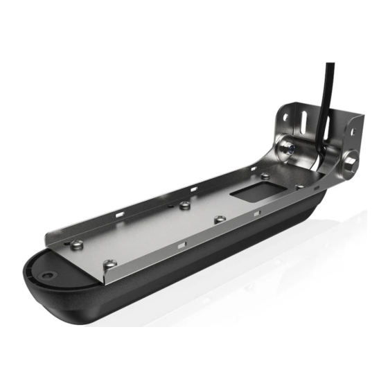
Parts included The transom mounting bracket assembly parts and a hardware mounting kit are included with the transducers. The transducer has a cable attached with a 9 pin connector. Transom mount plate Transducer bracket mount plate Transducer with cable attached Hardware mounting kit (included) Transom mount screws #10x1-1/4"... - Page 5 Required tools and supplies (not included) Drill Phillips (cross-head) screwdriver Drill bits Marine high-grade above- or below- waterline sealant/adhesive compound Parts included | Active Imaging transducers Installation Manual...
-
Page 6: Installation
Installation Mounting options The transducer can be mounted on the transom, jackplate, or step. Use the following table to determine which mounting option is best suited to your boat/installation preferences. Ú Note: When installing, keep the transducer on the protective foam nest where the transducer is placed from factory. - Page 7 Do not mount the transducer under the hull or so that it hangs down under the hull. The transducer is better protected when mounted above the bottom of the hull. There is less chance of damage from obstructions in the water, or when trailering and launching the boat.
-
Page 8: Transducer Angle
Transducer mounting options • Transducer is not in the water when boat "Direct Step mount (Flush is on plane; protects transducer and bracket)" on page 13 prevents drag from transducer Requires separately • Transducer angle cannot be adjusted so sold Skimmer Flush it is parallel with the water mount kit (part no. -
Page 9: Transom And Step Mount (Transom Bracket)
Ú Note: The Active Imaging 3-IN-1 transducer includes a broadband sounder. As a result, the DownScan Overlay and FishReveal broadband images work perfectly every time since the images come from the same place. - Page 10 Transom mount bracket assembly Ú Note: Ensure the cable has been threaded through the bracket before running the cable through the boat. Transom mount The transducer can be mounted on a transom bracket. With this mounting option the transducer can be in the water when you are on plane, or can be mounted so it is only in the water when you are moving at trolling speed.
- Page 11 Attach the transducer to the bracket mount plate using the 6 M4 attachment screws and M4 lock washers. Loosely attach the transducer bracket mount plate to the transom mount plate using M6 screws and nuts. Be careful to run the cable between the bracket mount plate and the transom mount plate before inserting the screws.
- Page 12 Step mount using the transom bracket The transducer can be mounted on a transom bracket. With this mounting option the transducer can be in the water when you are on plane, or can be mounted so it is only in the water when you are moving at trolling speed.
-
Page 13: Direct Step Mount (Flush Bracket)
Connect the transducer cable to the sonar port on the display or sonar module. After the transducer is connected and your boat is in the water, ensure what is shown on the left and right side on your display corresponds with what is on the left and right side of your boat. If they are showing opposite of what they should, turn on the Flip Left/Right feature in your display unit to correct it. - Page 14 Direct step mount installation Ú Note: Do not install the transducer under the hull. You can mount the transducer in either direction; with the cable coming out towards or away from the transom when installing with the direct step (Flush bracket) mount. However, after the transducer is connected and your boat is in the water, you need to check what is shown on the left and right side on your display corresponds with what is on the left and right side of your boat.
-
Page 15: Jackplate Mount Using The Transom Bracket
Attach the transducer to the flush bracket using the M4 transducer attachment screws and lock washers. Hold the assembly in the desired position. Use a pencil to mark the pilot holes through the mounting holes on the flush bracket. Drill the pilot holes. Apply a marine high-grade above- or below-waterline sealant/ adhesive compound to the pilot holes. - Page 16 Jackplate mount supplies (not included) 6 mm (1/4”) Drill bit (Jackplate M6 (1/4”) jackplate mount bolts Mount) Warning: Before installing the transducer on the jackplate, lower the jackplate to its lowest setting to make sure there is enough clearance between the jackplate, engine, transom, and the transducer.
- Page 17 careful that the cable is properly routed between the transom mount plate and the transducer mount plate. Slide the second M6 bolt into the bottom hole you drilled on the side of the jackplate, the transducer mount plate holes and the transom mount plate holes.
-
Page 18: Transducer And Transom Mount Bracket
Dimensions Transducer and transom mount bracket 67.0 mm (2.63”) 250.0 mm (9.84”) 257.0 mm (10.11”) 280.0 mm (11.02”) Active Imaging SideScan and Active Imaging 3-IN-1 transducer cables Ú Note: The transducers come with either a 7.6 m (25 ft) cable or a 1.83 m (6 ft) cable attached. -
Page 19: Parts And Accessories
Parts and accessories The most up-to-date parts and accessories are available at: www.simrad-yachting.com or www.lowrance.com. Active Imaging 3-IN-1 transducer (000-14489-001) Includes the transducer with cable, transom mounting bracket assembly and mounting screws, washers, and nuts. Active Imaging SideScan transducer (000-14490-001) Includes the transducer with cable, transom mounting assembly and mounting screws, washers, and nuts. -
Page 20: Technical Specifications
Technical specifications Active Imaging 3-in-1 transducer Environmental Operating temperature -15°C to +55°C (+5°F to +131°F) Storage temperature -30°C to +70°C (-22°F to +158°F) Physical Dimensions See "Dimensions" on page 18 Cable length 7.6 m (25 ft) or 1.8 m (6 ft) -
Page 21: Active Imaging Sidescan Transducer
Active Imaging SideScan transducer Environmental Operating temperature -15°C to +55°C (+5°F to +131°F) Storage temperature -30°C to +70°C (-22°F to +158°F) Physical Dimensions See "Dimensions" on page 18 Cable length 7.6 m (25 ft) or 1.8 m (6 ft) Mounting options Transom, flush step, and jackplate mounting Number of pins 9 pins Transducer... -
Page 22: Troubleshooting Tips
Troubleshooting tips Troubleshooting tips • Check unit software is compatible • Check transducer cable is connected to display unit or sonar module (and it is connected to the display unit) Transducer data not • Check sonar is enabled in display unit, displayed refer to display unit Operator manual •... - Page 24 www.simrad-yachting.com...
Need help?
Do you have a question about the Active Imaging 3-IN-1 and is the answer not in the manual?
Questions and answers