Frymaster BIELA14-T Series Service Manual
Gen iii lov
Hide thumbs
Also See for BIELA14-T Series:
- Manual (29 pages) ,
- Installation, operation and maintenance manual (82 pages)
Table of Contents
Advertisement
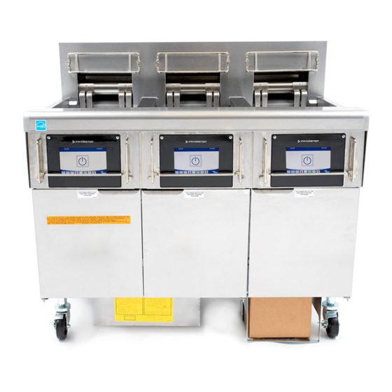
BIELA14-T Series
Gen III LOV
Service Manual
This manual is updated as new information and models are released. Visit our website at
www.frymaster.com
for the latest manual.
FOR YOUR SAFETY
Do Not Store or use gasoline or other
flammable vapors and liquids in the
vicinity of this or any other appliance.
*8197548*
Part Number: FRY_SM_8197548 10/2018
Original Instructions
™
Electric Fryer
Your Growth Is Our Goal
Advertisement
Table of Contents
Troubleshooting

Related Manuals for Frymaster BIELA14-T Series


Summary of Contents for Frymaster BIELA14-T Series
- Page 1 Your Growth Is Our Goal BIELA14-T Series Gen III LOV ™ Electric Fryer Service Manual This manual is updated as new information and models are released. Visit our website at www.frymaster.com for the latest manual. FOR YOUR SAFETY...
- Page 2 NOTICE IF, DURING THE WARRANTY PERIOD, THE CUSTOMER USES A PART FOR THIS FRYMASTER FOOD SERVICE EQUIPMENT OTHER THAN AN UNMODIFIED NEW OR RECYCLED PART PURCHASED DIRECTLY FROM FRYMASTER, OR ANY OF ITS FACTORY AUTHORIZED SERVICERS, AND/OR THE PART BEING USED IS MODIFIED FROM ITS ORIGINAL CONFIGURATION, THIS WARRANTY WILL BE VOID.
- Page 3 This fryer has a power cord (three-phase) for each frypot and may have a single five-wire cord for the entire system. Prior to movement, testing, maintenance and any repair on your Frymaster fryer; disconnect ALL electrical power cords from the electrical power supply.
- Page 4 DANGER No structural material on the fryer should be altered or removed to accommodate placement of the fryer under a hood. Questions? Call the Frymaster Dean Service Hotline at 1-800-551-8633. WARNING Do not block the area around the base or under the fryers.
-
Page 5: Table Of Contents
Table of Contents Section 1: Service Procedures M4000 Menu Summary Trees ..........................1-1 1.1.1 M4000 Menu Tree ..........................1-1 1.1.2 M4000 Information Statistics Menu Tree ..................1-2 M4000 Password Codes ............................1-3 Service Required Errors ............................1-3 Error Log Codes ..............................1-3 Component Check ..............................1-5 Troubleshooting and Problem Isolation … ......................1-6 1.6.1 General ...............................1-6 1.6.2... - Page 6 1.12.2 VIB (Valve Interface Board) Pin Positions and Harnesses ............1-33 1.12.3 Replacing a VIB (Valve Interface Board) Board ................1-34 1.12.4 Replacing a Rotary Actuator ......................1-34 1.13 Control Power Switch ............................1-34 1.14 Leakage…................................1-34 1.15 Loading and Updating Software Procedures ....................1-35 1.16 Replacing Fryer Components ...........................
- Page 7 LOV-T™ ELECTRIC WARRANTY STATEMENT Frymaster, L.L.C. makes the following limited warranties to the original purchaser only for this equipment and replacement parts: A. WARRANTY PROVISIONS - FRYERS 1. Frymaster L.L.C. warrants all components against defects in material and workmanship for a period of two years.
- Page 8 improper maintenance; damage in shipment; abnormal use; removal, alteration, or obliteration of either the rating plate or the date code on the heating elements; operating the frypot without shortening or other liquid in the frypot; no fryer will be warranted for which a proper start-up form has not been received.
-
Page 9: Section 1: Service Procedures
BIELA14-T SERIES GEN III LOV™ ELECTRIC FRYERS CHAPTER 1: SERVICE PROCEDURES M4000 Menu Summary Trees 1.1.1 M4000 Menu Tree Reflected below are the major programming sections in the M4000 and the order in which the headings will be found in the controller. -
Page 10: M4000 Information Statistics Menu Tree
1.1.2 M4000 Information Statistics Menu Tree Reflected below are the information statistics in the M4000 and the order in which the headings will be found in the controller. -
Page 11: M4000 Password Codes
1.2 M4000 Password Codes Press the HOME button to enter MENUS, RECIPES, SETTINGS or SERVICE menus. 1234 – MENUS, RECIPES, SETTINGS (MANAGER) 4321 – SERVICE (MANAGER) 1650 – SETTINGS (SERVICE), SERVICE (SERVICE) Enter Tech Mode 9000 – Component Check [SETTINGS (SERVICE), SERVICE (SERVICE) Enter Tech Mode] ... - Page 12 Code ERROR MESSAGE EXPLANATION AUTOMATIC INTERMITTENT FILTRATION AIF (VIB Probe) RTD reading out of range. PROBE FAILURE - FILTRATION DISABLED - CALL SERVICE CHANGE FILTER PAD 25-hour timer has expired or dirty filter logic has activated. OIL IN PAN ERROR The system detects that oil may be present in the filter pan.
-
Page 13: Component Check
1.5 Component Check The M4000 controller has a function to check the major components and their status. With the controller soft powered OFF, press the HOME button. Select Service, Service, Enter 9000, Select Tech Modes, and scroll down and select Component Check. The component name is above each button. -
Page 14: Troubleshooting And Problem Isolation
An additional set of operators troubleshooting guides are contained in Chapter 7 of the BIELA14-T Series Installation and Operation Manual. It is suggested that service technicians thoroughly familiarize themselves with both sets. -
Page 15: Heating Failure
Heating Failure Heating failure occurs when the heating contactor fails to stay engaged and locks out. When this happens, the module sends 24 VAC through the interface board alarm circuit to the controller. M4000 controllers display “HEATING FAILURE”. The three primary reasons for heating failure, listed in order of probability, are problems related to: Electrical power supplies Electronic circuits Contactor issues... -
Page 16: Smart Interface Board (Sib)
SMART INTERFACE BOARD LED DIAGNOSTIC LIGHTS 1.7.2 Smart Interface Board (SIB) LED 1 24VAC Heat Relay All fryers in this series have a smart interface board (SIB) located in the LED 2 12VDC to Controller LED 3 24VAC Latch Relay component box behind the controller panel. - Page 17 1.7.3 Full/Split Vat flow through the SIB (Smart Interface Board)
-
Page 18: Frequently Used Test Points For Sib
1.7.4 Frequently Used Test Points for SIB (Smart Interface Board) NOTE: DO NOT CHECK WITH HARNESSES UNPLUGGED AS SHORTING THE PINS MAY OCCUR WHICH WILL DAMAGE THE BOARD. FREQUENTLY USED TEST POINTS FOR INTERFACE BOARD 1085979 Meter Test Setting Pins Results 24VAC Power to SIB 50VAC Scale... -
Page 19: Sib (Smart Interface Board) Pin Positions And Harnesses
1.7.6 SIB (Smart Interface Board) Pin Positions and Harnesses NOTE: DO NOT CHECK WITH HARNESSES UNPLUGGED (except ATO and Temp Probes) AS SHORTING THE PINS MAY OCCUR WHICH WILL DAMAGE THE BOARD. Wire Connector From/To Harness # Function Voltage Color From Transformer 24VAC Input 24VAC... -
Page 20: Replacing Control Box Components (Smart Interface Board (Sib)), Transformer
Filter Relay (Left Box Only); Reset Switch Relay (Right Box Only) 1.7.7 Replacing Control Box Components (Smart Interface Board (SIB), transformer, relay Perform steps 1 through 8 from section 1.9.3. Remove the bezel by removing the two (2) screws on the bottom of the bezel. -
Page 21: Troubleshooting The Temperature Probe
1.8.2 Troubleshooting the Temperature Probe CAUTION Disconnect the temperature probe from the SIB board before testing temperature probe resistances to avoid invalid readings. Prior to checking for problems associated with the temperature probe, inspect the probe body for damage while it is still in the frypot. -
Page 22: Replacing The Temperature Probe
Reconnect the 12-pin connecting plug C-6. Use wire ties to secure any loose wires. Reinstall the back panels, contactor plug guards, reposition the fryer under the exhaust hood, and reconnect it to the electrical power supply to return the fryer to service. -
Page 23: M4000 Controller Troubleshooting
The test results will be displayed in minutes and seconds. The maximum acceptable recovery time for BIELA14-T Series LOV™ electric fryers is one minute and forty seconds (1:40) for liquid shortening and three minutes (3:00) for solid shortening. If the recovery is high, check to ensure that the fryer 3-phase plugs are fully seated into the receptacle. - Page 24 Problem Probable Causes Corrective Action M4000 displays VAT ID Vat ID locator connector Ensure that the vat locator connector is properly CONNECTOR NOT unplugged from UI or grounded connected to UI harness and ensure that ground on CONNECTED position in control box. harness is properly grounded to control box.
-
Page 25: M4000 Controller Functional Troubleshooting
Problem Probable Causes Corrective Action This indicates a problem within the temperature Problem with the temperature measuring circuitry. Check resistance of probe, if M4000 displays E13 measuring circuitry including faulty replace probe. TEMPERATURE PROBE the probe. Ensure temperature probe is connected properly FAILURE CALL SERVICE. -
Page 26: Replacing The Controller Or The Controller Wiring Harnesses
1.9.3 Replacing the Controller or the Controller Wiring Harnesses 1. Di sconnect the fryer from the electrical power supply. The fuse located at the bottom of the control box can be removed to remove power from individual control boxes. The controller is held in place by two screws in upper corners. Remove the two screws from the upper corners of the controller. -
Page 27: Filtration Malfunctions
1.10 Filtration Malfunctions 1.10.1 Built-in Filtration System Service Procedures Most filtration problems arise from operator error. One of the most common errors is placing the filter paper/pad on the bottom of the filter pan rather than over the filter screen. Whenever the complaint is “the pump is running, but no oil is being filtered,”... -
Page 28: Filtration Troubleshooting
Incorrectly sized or installed filter paper/pads will also allow food particles and sediment to pass through and clog the suction tube on the bottom of the filter pan. Particles large enough to block the suction tube may indicate that the crumb tray is not being used. -
Page 29: Fib (Filter Interface Board) Service Procedures
Problem Probable Causes Corrective Action Power cord is not Verify that the power cord is fully plugged in and the plugged in or circuit circuit breaker is not tripped. breaker is tripped. Filter pump won’t start If the motor is too hot to touch for more than a few or pump stops during Pump motor has seconds, the thermal overload switch has probably... -
Page 30: M4000 Filter Error Flowchart
1.10.6 M4000 Filter Error Flowchart If the controller displays SERVICE This chart follows the process of clearing a filtration issue. REQUIRED, the fryer can be used in The prompt is displayed when any of the following occur: some cases by answering NO when the prompt for SYSTEM ERROR 1. -
Page 31: Replacing The Filter Motor Or Filter Pump
1.10.7 Replacing the Filter Motor or Filter Pump Disconnect the fryer from the electrical power supply and reposition it to gain access to both the front and rear. Remove the filter pan and lid from the unit. Remove the lower back panel. Disconnect the flexline running to the oil-return manifold at the rear of the fryer as well as the pump suction flexline at the end of the filter pan connection. -
Page 32: Ato (Automatic Top-Off Troubleshooting)
Problem Probable Causes Corrective Action Clear filter error properly. When “CHANGE FILTER PAD YES/NO” is displayed, do NOT press any button Filter error exists. until the pan has been removed for at least thirty One vat doesn’t top off. Actuator, pump, loose seconds. - Page 33 Problem Probable Causes Corrective Action Enter the INFO mode, and select SOFTWARE, review the FIB software status. If FIB: 00.00.000 is shown, the communication is lost between the FIB and SIB or the CAN bus is loaded down. This can be caused by a defective SUI board (if installed).
- Page 34 Problem Probable Causes Corrective Action Power to the FIB board has been lost. Ensure there Continued from is correct voltage to the FIB power supply and from previous page. the FIB power supply. Restore power to the board and clear any service required errors. Replace FIB M4000 displays E64 - power supply.
-
Page 35: Test Points On Rear Of Fib Box
1.11.2 Test Points on rear of FIB Box 1.11.2.1 12-pin connector on rear of FIB (Filter 24VAC + HOT Dispose Interface Board) box (C7) Bulk Oil Closed + Transformer Dispose 24VAC these test points Open ‐ Fresh Oil troubleshooting. Solenoid + 24VAC 24VAC COM ‐... -
Page 36: Fib (Filter Interface Board) Led's And Test Points
1.11.3 FIB (Filter Interface Board) LED’s and Test Points Figure 20 1-28... -
Page 37: Fib (Filter Interface Board) Filtration Top-Off Pin Positions And Harnesses
1.11.4 FIB (Filter Interface Board) Filtration and Top-off Pin Positions and Harnesses NOTE: DO NOT CHECK WITH HARNESSES UNPLUGGED AS SHORTING THE PINS MAY OCCUR WHICH WILL DAMAGE THE BOARD. Connec Harness Wire From/To Function Voltage Color Brown Ground - +24VDC Purple 24VDC Input... -
Page 38: Replacing The Ato Pump Or Solenoid
1.11.5 Replacing the FIB Board, Power Supply, or optional SUI Communication Board Disconnect the fryer from the electrical power supply. Locate the FIB FIB Board box (see Figure 17 in section 1.11), behind the oil reservoir). Remove the cover of the FIB box to expose the power supply, FIB board and optional SUI communication board (see Figure 21). -
Page 39: Vib (Valve Interface Board) Service Procedures
1.12 VIB (Valve Interface Board) Service Procedures The VIB (Valve Interface Board) controls the actuators that open and close the drain and return valves. The VIB boards are located inside a protective housing under each frypot (see Figure 25). Figure 25 Figure 26 1-31... -
Page 40: Vib (Valve Interface Board) Troubleshooting
1.12.1 VIB (Valve Interface Board) Troubleshooting NOTE: DO NOT CHECK WITH HARNESSES UNPLUGGED AS SHORTING THE PINS MAY OCCUR WHICH WILL DAMAGE THE BOARD. Problem Probable Causes Corrective Action Check pins 4 and 5 of J2 at the FIB board. Should read 24VDC. - Page 41 1.12.2 VIB (Valve Interface Board) Actuator Board Pin Positions and Harnesses NOTE: DO NOT CHECK WITH HARNESSES UNPLUGGED AS SHORTING THE PINS MAY OCCUR WHICH WILL DAMAGE THE BOARD. Connector From/To Harness PN Pin # Function Voltage Wire Color Right VIB Probe Yellow Ground Right VIB Probe...
-
Page 42: Replacing A Vib (Valve Interface Board) Board
1.12.3 Replacing a VIB (Valve Interface Board) Disconnect the fryer from the electrical power supply. Locate the VIB (valve interface board) to be replaced under a frypot. Mark and unplug the harnesses. The VIB assembly is held in place with one screw (see Figure 27). Remove the screw and the assembly drops down (see Figure 28) and the tab slides out of the bracket attached to the frypot (see Figure 29). -
Page 43: Loading And Updating Software Procedures
1.15 Loading and Updating Software Procedures Updating the software takes approximately 30 minutes. The software only needs to be loaded in the USB port in the far- left fryer cabinet and it will update all the controllers and boards in the system. To update the software, follow these steps carefully: Switch all controllers to OFF. -
Page 44: Replacing Fryer Components
1.16 Replacing Fryer Components 1.16.1 Replacing Contactor Box Components Disconnect the fryer from the electrical Contactors power supply. Hood Relay Relocate the fryer if necessary. If replacing the hood relay remove the left side of the fryer. Locate the contactor box. Remove the two screws securing the cover of the contactor box cover from the contactor box (see Figure 35). - Page 45 Route the element leads through the element tube assembly and into the wire sleeving to prevent chafing. Ensure that the wire sleeving is routed back through the Heyco bushing, keeping it clear from the lift springs (see photos below). Also ensure that the wire sleeving extends into the tube assembly to protect the edge of the tube assembly from chafing the wires.
-
Page 46: Replacing A Frypot
Element grounding and wire routing To ground the element wires, use the hole in the frypot frame located under the bushing that the element wires pass through. Using a screw through ground wires ring terminal, connect it to the frypot using the probe ground clip. -
Page 47: Wiring Diagrams
32. Reinstall controllers in the control panel frame and reconnect the wiring harnesses and ground wires. 33. Reposition the fryer under the exhaust hood and reconnect it to the electrical power supply. 1.17 Wiring Diagrams See 8197343 McDonald’s BIELA14-T Series Gen III LOV Electric Wiring Diagrams Manual 1-39... -
Page 48: Appendix A Rti Service Issues
BIELA14-T SERIES GEN III LOV™ ELECTRIC FRYERS Appendix A: RTI (Restaurant Technology Inc.) Service Issues A.1 RTI FIB Tests RTI (Restaurant Technology Inc.) provides fresh and waste bulk oil service for McDonald’s. The instructions in this manual for using a bulk oil system for filling and discarding oil are for an RTI system only. - Page 49 A.2 RTI LOV™ Wiring with RTI Switchbox Figure 1 A.3 Frymaster LOV™ Fryer and RTI Bulk Oil System Plumbing Schematic Figure 2 A–2...
- Page 50 A.4 RTI LOV™ TEST QUICK REFERENCE A.4.1 DISPOSE TO WASTE, REFILL VAT FROM BULK: Press the filter button. Select LEFT VAT or RIGHT VAT for split vats. Select DISPOSE OIL. “DISPOSE OIL? YES/NO” is displayed. * Press the √ (check) button to dispose of oil in vat. “DRAINING IN PROGRESS”...
- Page 51 16. “IS PAN EMPTY? YES/NO” is displayed. 17. Press the √ (check) button if the filter pan is empty. Select “NO” if oil remains in the filter pan. 18. “INSERT PAN” is displayed. 19. Insert the filter pan. 20. “CLOSE DISPOSE VALVE” is displayed. 21.
- Page 52 FRYMASTER 8700 LINE AVENUE, SHREVEPORT, LA 71106‐6800 800‐551‐8633 318‐865‐1711 WWW.FRYMASTER.COM EMAIL: FRYSERVICE@WELBILT.COM *8197423* WWW.WELBILT.COM Welbilt provides the world’s top chefs, and premier chain operators or growing independents with industry leading equipment and solutions. Our cutting‐edge designs and lean manufacturing tactics are powered by deep knowledge, operator insights, and culinary expertise. All of our products are backed by KitchenCare® – our aftermarket, repair, and parts service. CLEVELAND DELFIELD® FRYMASTER® KOLPAK® MANITOWOC® MERRYCHEF® CONVOTHERM® FITKITCHEN™ GARLAND LINCOLN MERCO® MULTIPLEX® ©2018 Welbilt Inc. except where explicitly stated otherwise. All rights reserved. Continuing product improvement may necessitate change of specifications without notice.
Need help?
Do you have a question about the BIELA14-T Series and is the answer not in the manual?
Questions and answers