Advertisement
Quick Links
DESCRIPTION
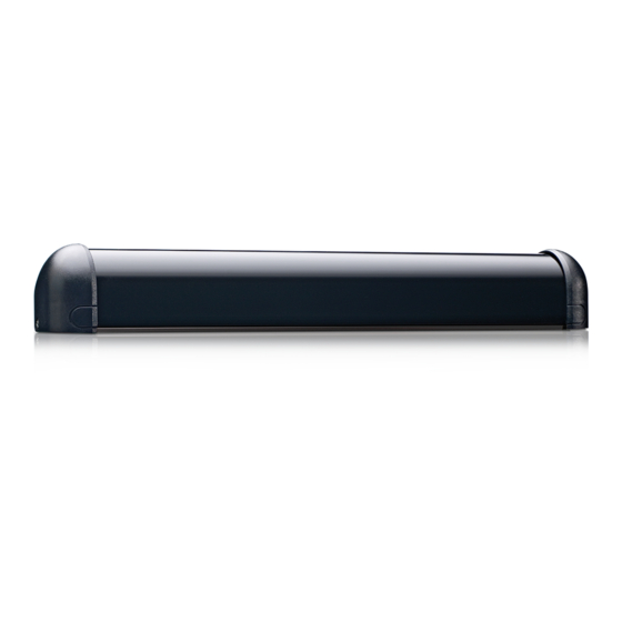
The SuperScan (10SSI, 10SSII, 10SSIII) detector is a door-mounted presence detection system that is used on automatic
pedestrian swing doors. The SuperScan can be used on an SMR or non-SMR system. Unlike other door-mounted sensing
devices, the SuperScan's unique electronic architecture allows the detection modules to be mounted near the top of the
door, out of harm's way. A rotating cam is used for the range adjustment of the detection zone. Width patterns may be
altered by adding slave modules to the master module. These slave modules are simply added by inserting them into the
aluminum extrusion, then connecting them with the attached flat ribbon cable to the next module without interrupting other
modules in the same extrusion. Once installed, the detection zone (in addition to being adjustable for distance) can be
angled independently from the other modules.
Each SuperScan module consists of two optics, a transmitter (TX) and a receiver (RX), and functions independently of the
other modules. The transmitter emits an extremely precise beam, which measures approximately 4" in diameter at a
distance of 8'. The receiver, in turn, receives the infrared beam reflected off of the floor. This transmission and reception
forms a detection triangle, which is the basic premise of detection (called triangulation). Should this angle be interrupted,
detection will occur. Detection is NOT based upon the intensity of the beam, and in principle will not be affected by the color
or background of the object that interrupts the angle.
TECHNIC
SPECIFICATIONS
SAFETY
PRECAUTIONS
!
CAUTION
SuperScan Assembly
Wire Transfer Sheath
8-Wire Cable
75.0084.05 20110720
DESCRIPTION
Power Supply
Current Consumption:
Input Inhibit
SMR Input Data
Output Interface; relay
Detection Range
Distance Adjustment
Max. Mounting Height
Detection Time
Detection Signal Duration
Output Hold Time
LED Indications
Operating Temperature
Range
PCB Dimensions
Connection to Door
Controller
Connection: Master to
Slave
Max. Number of Slaves
Functions Selection
• Shut off all power going to the header before attempting any wiring procedures.
• Maintain a clean & safe environment when working in public areas.
• Constantly be aware of pedestrian traffic around the door area.
• Always stop pedestrian traffic through the doorway when performing tests that may result in unexpected
reactions by the door.
• Always check placement of all wiring and components before powering up to ensure that moving door parts
will not catch any wires and cause damage to equipment.
• Ensure compliance with all applicable safety standards (i.e. ANSI A156.10, 156.27) upon completion of
installation.
SPECIFICATION
12 to 24 VAC ± 10% / 12 to 24 VDC + 10%
Master: On = 60 mA max. / Master: Off = 30 mA max.
Slave: On = 40 mA. Max. / Slave: Off = 30 mA max.
12 to 24 VAC ± 10%: / 12 to 24 VDC + 10% / Inhibited when voltage is applied
12-18 VDC: Inhibited when voltage is applied
Relay; max. contact rating is 1A @ 30v ( resistive)
0' to 8'
2' to 8' / Rotating cam with linear adjustment
8'
< 50 ms
Infinite Presence Detection
Potentiometer Range: 0.1 to 4.5 seconds.
Master: Red LED = Detection
Green LED = Active Output
Slave: Red LED = Detection
-30° F to 140° F
Master: 10.91" x 1.5"
Slave: 8.75" x 1.5"
8 Position Screw Terminal on Master PCB
Flat Ribbon Cable With Connectors and Key Lock
Standard = 9 / With Monitoring = 8 max.
Detection Mode - NO or NC
Normal Mode or Background Analysis Mode
SUPERSCAN
USER'S GUIDE
PRESENCE SENSOR
Jamb Hole Cover
Page 1 of 17
Advertisement

Related Manuals for BEA SuperScan


Summary of Contents for BEA SuperScan
- Page 1 Each SuperScan module consists of two optics, a transmitter (TX) and a receiver (RX), and functions independently of the other modules. The transmitter emits an extremely precise beam, which measures approximately 4" in diameter at a distance of 8'.
-
Page 2: Installation Tips
(finger guards, lock objects likely to move or rods, etc.). vibrate in its path. MECHANICAL Remove the screw that secures the end cap to the SuperScan extrusion (as shown in Picture 1 below). INSTALLATION- PREPARING AND MOUNTING THE SENSOR Remove the plastic lens by pulling the lens out from the top of the extrusion (as shown in Picture 2 above). - Page 3 Hold the SuperScan back up to the door at the pre-drilled location and attach the unit to the door with the 2 screws provided. Insure that the SuperScan extrusion is tight against the door.
- Page 4 Next, a wire passage hole will be required in the door header (Picture 15) and also in the jamb tube (Picture 16) at INSTALLATION- approximately the same height as the SuperScan. The wire transfer hole in the jamb should be at the secure side of PREPARING AND the door.
- Page 5 ELECTRICAL Once all wiring has been completed, the end caps and lens may be installed. At the SuperScan end of the cable INSTALLATION- (picture 23), leave enough slack to allow a relaxed connection at the terminal block. Locate the Superscan end cap CABLING &...
- Page 6 MECHANICAL ADJUSTMENTS - J2 is a two-position jumper, which enables either a passive or active relay to be selected. The SuperScan comes PRIOR TO factory preset with the relay in the ACTIVE MODE. J2 IS ON THE MASTER BOARD ONLY.
- Page 7 If a Slave ONLY is shipped: No jumper on Slave J4 position If a kit is shipped (i.e. SuperScan II): Jumpers correctly placed for that configuration. On the slave module, jumper J4 should be installed on the last slave module in the chain, as shown above in picture 32.
-
Page 8: Compatibility List
MASTER / SLAVE MASTER AND SLAVE MODULE COMPATIBILITY TABLE CONFIGURATION Compatible: √ MASTER Not Compatible: X Config.1 SMR Config.2 SMR Config.3 Non SMR COMPATIBILITY LIST Config.1 SMR √ √ Config.2 SMR √ √ Config.3 Non SMR √ √ √ MASTER MODULES Configuration 3 –... - Page 9 The positioning of the modules within the aluminum extrusion will be as shown below. The modules will always be MECHANICAL positioned so that the transmitter (TX) is at the leading edge of the door. Modules may be flipped around to ADJUSTMENTS –...
-
Page 10: View From Above
POWER-ON POSITIONING, INACTIVE ZONE SUPERSCAN ANGLE (C) ANGLING AND 0° 5° 10° 15° 20° 25° (B) DISTANCE ADJSUTING THE FROM FLOOR MODULES 6" 12 ½" 19 ¼" 26" 33 ¼" 8" 6" 12" 18" 24 ½" 31 ½" 12" 5 ½"... - Page 11 Check for: position. Proper detection angle Detection range adjustment SuperScan may need to be inhibited at a specific point of door travel at the safety side for proper operation. Refer to the terminal connections on page 4.
- Page 12 A safety check that includes at a minimum the items listed on the safety information label must be performed during each service call. If you are not an AAADM certified inspector BEA strongly recommends to have an AAADM certified inspector perform an AAADM inspection and placing a valid inspection sticker below the safety information label prior to placing the equipment into operation.
- Page 13 ADDENDUM – SCHEMATICS EMPTY INHIBIT GND 2 INHIBIT + N.C. N.O. POWER POWER EMPTY INHIBIT GND 2 INHIBIT + N.C. N.O. POWER POWER EMPTY INHIBIT GND 2 INHIBIT + N.C. N.O. POWER POWER EMPTY INHIBIT GND 2 INHIBIT + N.C. N.O.
- Page 14 ADDENDUM - SCHEMATICS (Continued) EMPTY INHIBIT GND 2 INHIBIT + N.C. N.O. POWER POWER EMPTY INHIBIT GND 2 INHIBIT + N.C. N.O. POWER POWER N.C. N.O. green EMPTY white INHIBIT GND 2 POWER 2 black INHIBIT + POWER 1 N.C. BROWN N.O.
- Page 15 SCHEMATICS (Continued) EMPTY INHIBIT GND 2 INHIBIT + N.O. BROWN N.C. WHITE POWER BLACK POWER EMPTY INHIBIT GND 2 SUPERSCAN QUICK- INHIBIT + DISCONNECT CABLE N.O. BROWN N.C. WHITE BLACK POWER POWER EMPTY INHIBIT GND 2 INHIBIT + N.O. GREEN N.C.
- Page 16 SCHEMATICS (Continued) EMPTY INHIBIT GND 2 INHIBIT + N.C. BROWN N.O. BLUE POWER BLACK POWER EMPTY INHIBIT GND 2 SUPERSCAN QUICK DISCONNECT CABLE INHIBIT + N.C. BROWN N.O. BLUE BLACK POWER POWER EMPTY INHIBIT GND 2 INHIBIT + N.C. GREEN N.O.
- Page 17 ADDENDUM - If a wall or a guardrail is detected by the SuperScan in the opening cycle, the SuperScan will need to be inhibited before SCHEMATICS the detection is allowed to stall the door. For some operators, the back check switch can be used to shut the SuperScan (Continued) off before the detection occurs.
Need help?
Do you have a question about the SuperScan and is the answer not in the manual?
Questions and answers