Table of Contents
Advertisement
88688A23
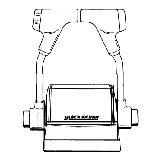
DUAL HANDLE TRIM
CONTROL
INSTALLATION,
OPERATION AND
MAINTENANCE
INSTRUCTIONS
NOTICE to INSTALLER
After Completing Installation, These Instruc-
tions Should Be Placed with the Product For
the Owner' s Future Use.
Do not use external tie bar with this dual handle trim
control or damage to drive units may result if improp-
erly trimmed.
Printed in U.S.A.
Index
Notice to Installer/Owner
....................................
....................................
All MerCruiser Models (Except MIE) and Out-
board Models (250 HP 3 Litre and Below)
.................................
All MerCruiser Models (Except MIE) and Out-
board Models (250 HP 3 Litre and Below)
.................................
Starboard Side Control Module Cable Installation
Outboard Models 250 HP 3.4 Litre and Above
Shift Cable
.................................
Throttle Cable
Port Side Control Module Cable Installation
Outboard Models 250 HP 3.4 Litre and Above
Shift Cable
.................................
Throttle Cable
...............................
.................................
Operation . . . . . . . . . . . . . . . . . . . . . . . . . . . . . . . . . . . . .
- 1 -
........................
.............
................
..............................
..............................
..............................
..............................
.......................
..............
........................
...................
-812625
90
Page
4
.......
4
4
.......
5
5
5
...
6
6
6
7
...
7
7
8
8
8
10
10
11
13
l-395
Advertisement
Table of Contents

Summary of Contents for Quicksilver 88688A23
-
Page 1: Table Of Contents
Maintenance and Replacement Parts ..... Selecting Remote Control Cables ....Introduction ........Installation ........88688A23 Starboard Side Control Module Cable Installation All MerCruiser Models (Except MIE) and Out- DUAL HANDLE TRIM board Models (250 HP 3 Litre and Below) ..Shift Cable ......... -
Page 2: Maintenance And Replacement Parts
Selecting Remote Control vention measures. Cables DANGER - Immediate hazards which WILL result in Refer to outboard “ Quicksilver Dealers’ Guide” to severe personal injury or death. determine correct length of control cables. IMPORTANT: Remote control cables MUST BE THE... -
Page 3: Introduction
Introduction 5. Final Checks and Adjustments. a. Re-check tightness of control handle set screw. This console mount control provides complete one Set screw should be torqued to 60 lb in. (7 N.m.) hand operation of the shift and throttle control. The control is equipped with a neutral start switch which b. - Page 4 Starboard Side Control Throttle Cable Module Cable Installation All MerCruiser Models (Except MIE) and Outboard Models (250 HP 3 Litre and Below) IMPORTANT: Control modules are stamped port and starboard and control cables must be installed ac- cordingly. Before tightening cable fastener locknut, be sure that pin on end of cable fastener is completely thru cable end and shift/throttle lever.
-
Page 5: All Mercruiser Models (Except Mie) And Out Board Models (250 Hp 3 Litre And Below)
Port Side Control Throttle Cable Module Cable Installation All MerCruiser Models (Except MIE) and Outboard Models (250 HP 3 Litre and Below) Before tightening cable fastener locknut, be sure that pin on end of cable fastener is completely thru cable end and shift/throttle lever. -
Page 6: Starboard Side Control Module Cable Installation
Throttle Cable Starboard Side Control Module Cable Installation (Outboard Models 250 HP 3.4 Litre and Above) Before tightening cable fastener locknut, be sure that pin (on end of cable fastener) is completely thru cable end and shift/throttle lever. A pin, that is partially thru cable and lever, may cause fastener to bend when locknut is tightened. -
Page 7: Port Side Control Module Cable Installation Outboard Models 250 Hp 3.4 Litre And Above
Port Side Control Throttle Cable Module Cable Installation (Outboard Models Litre and Above) The control cables in the starboard side module are installed differently than those in the port side module, therefore, the back cover of each control has been stamped “... -
Page 8: Remote Control Mounting
Remote Control Mounting Mounting Control CAUTION 1. Place control modules back-to-back, then position This trim control can be connected only to Power a mounting bracket onto each module and secure Trims that are equipped with a 2-solenoid trim pump. If brackets and modules together with two 4 in. - Page 9 3. Feed control cables, neutral start safety switch wir- ing harnesses and trim harness thru control base Set screws in control handles must be torqued to speci- and opening in mounting panel (cut previously) and fication. Failure to tighten set screws securely could set control in position.
-
Page 10: Trailer Switch Installation
Trailer Switch Installation IMPORTANT: Route switch to desired location to ensure adequate wire length and clearance behind mounting area. Cut a 2-1/8 in. (54mm) diameter hole at desired location. Thread studs into bezel, tighten securely, but do not overtighten. Place switch thru mounting clamp opening and thru mounting area (from back). -
Page 11: Repositioning Control Handles
Repositioning Control 2. Pry trim switch retainer from shift/throttle handle. Handles NOTE: Repositioning of control handle (on control shafts) is necessary only if the standard neutral posi- tion of control handles are undesirable. IMPORTANT: When repositioning control handles (on control shaft), position handles so that full forward and reverse can be achieved. - Page 12 7. Rotate trim wires and trim wire rotator (on control shaft) to the position that neutral is desired when Control handle set screw must be torqued to specifica- control handle is reinstalled. tion. Failure to tighten set screws securely could allow control handle to disengage, with subsequent loss of throttle/shift control.
-
Page 13: Operation
Operation The Control handles feature full gear shift and throttle. Always shift with a firm, quick motion. Approximately the first 40-degrees of control han- dle travel (“ Forward” and “ Reverse” ) shifts the engines. Remainder of control handle movement advances the throttle. - Page 14 Template for Dual and Single Console Controls Outline of Remote Control Cover for Dual Control Centerline for a - l 3/8” (9.53mm) Dia. for Single Control Outline of Remote Control Cover for Single Control 1/4” (.25” or 6.35mm) Dia. for Single Control Centerline for Dual Control Area (located directly under mounting panel) must be free from obstructions and must allow cables to form a gradual bend when routed toward stern of...
Need help?
Do you have a question about the 88688A23 and is the answer not in the manual?
Questions and answers